INTERNATIONAL RESEARCH JOURNAL OF ENGINEERING AND TECHNOLOGY
(IRJET) E-ISSN: 2395 -0056
VOLUME:03ISSUE:06|JUNE-2016 WWW.IRJET.NET P-ISSN: 2395-0072© 2016, IRJET | Impact Factor value: 4.45 | ISO 9001:2008 Certified Journal | Page 291
Design and Investigation of Circular Polarized Rectangular Patch
Antenna
Rajkumar
1and Divyanshu Rao
21
Shri Ram Institute Technology, Jabalpur (M.P.),India
2
Prof. Divyanshu Rao, Shri Ram Institute Technology, Jabalpur (M.P.), India
ABSTRACT: Microstrip patch antennas represent one family of compact antennas that offer a conformal nature
and the capability of ready integration with communication system’s printed circuitry. In this project, a 2.4 GHz circular polarization microstrip antenna is designed, constructed and measured. The microstrip antenna chose is a dual –fed circular polarized microstrip antenna. The antenna consists of rectangular patch and 3 dB hybrid. The dual – fed circular polarized microstrip antenna is etched on a FR4 with dielectric substrate of 4.5 with the height of 1.6 mm. Circular polarization is obtained when two orthogonal modes are equally excited with 90° phase difference between them. Circular polarization is important because regardless of the receiver orientation, it will always able receiving a component of the signal. This is due to the resulting wave having an angular variation.
Index Terms—Microstrip Patch Antenna, Orthogonal Modes, and Circular Polarization.
I.
I
NTRODUCTIONt present wireless and microwave communication is dominating day by day.In microwave communication microstrip patch antenna technology is one of the rapid progressing communication field and which was started in mid 1970-80s. Basic microstrip antenna elements, arrays and polarization concept was well developed in form of design and modeling in the early 1980s [1]. In the last 10 years printed antennas/software based antenna have been largely researched/studied due to reduced size, their advantages over other radiating systems, such as very light weight, less expensive, both conformability and possibility of integration with both active and passive devices.
Therefore, this project work is aimed to design a circularly polarized antenna at 2.4 GHz. The best thing of circular polarization is no particular orientation i.e. in any orientation it will always receive a component of the signal. This is due to the producing or resulting wave having an circular variation [2].
This microstrip patch antenna has a radiating patch on the dielectric substrate. There are many shapes that can be used for radiating patch. However, for this project, we will select square patch with 3 dB hybrid With two orthogonal modes and dual feeding methods are equally excited with 90° phase difference between them, as a result antenna will act as polarize circularly.
The microstrip antenna is tested and simulated using Microwave Office v15, where different tools will be used e.g elecromagnetic analysis tools.
This microwave patch antenna will be fabricated and tested with network analyzer also. Both results will be compared i.e simulated and measured results.
II.
D
ESIGNED ANTENNAIn order to ease the processes of designing the microstrip antenna, the project is split into subtask, which allowed for achievable short term goals. The flow chart as in Figure 1, explains the process.
© 2016, IRJET | Impact Factor value: 4.45 | ISO 9001:2008 Certified Journal | Page 292 Figure 1: Design Flow Chart
Figure 2: Layout of the Microstrip Patch Antenna
[image:2.612.96.581.398.669.2]INTERNATIONAL RESEARCH JOURNAL OF ENGINEERING AND TECHNOLOGY
(IRJET) E-ISSN: 2395 -0056
VOLUME:03ISSUE:06|JUNE-2016 WWW.IRJET.NET P-ISSN: 2395-0072 [image:3.612.210.403.99.247.2]© 2016, IRJET | Impact Factor value: 4.45 | ISO 9001:2008 Certified Journal | Page 293
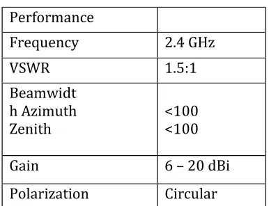
Table 1: Performance of microstrip antenna
Performance
Frequency
2.4 GHz
VSWR
1.5:1
Beamwidt
h Azimuth
Zenith
<100
<100
Gain
6 – 20 dBi
Polarization
Circular
For FR4 (εr = 4.5) and height (h) of 1.6mm, the overall value for the design antenna is as shown in Figure 2 and Table 1.
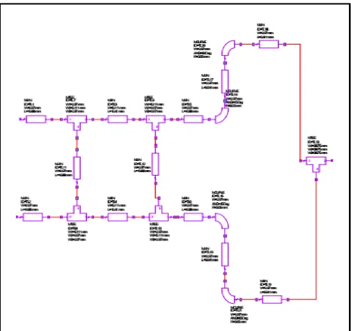
Then, the schematic diagram of the antenna is drawn by using the Microwave Office software. Figure 3 shows the schematic diagram for the designed microstrip patch antenna.
III.
S
IMULATION RESULTSThe return loss of the antenna can be obtained from the simulation process.Figure 5.5 shows that the return loss obtained is -23.25 dB at 2.474 GHz.The return loss also shows that only 0.47% power is reflected and 99.53% power is transmitted. The bandwidth can also be obtained from Figure 5.5. Formula for finding a bandwidth is as shown below:
Bandwidrh = {(f1 - f2)/(f1 f2)1/2}x100 % (1)
The value of f2 and f1 are taken 10% of power transmitted, or at 10 dB as shown in Figure 5.5. The value of f2 and f1 are taken 10% of power transmitted, or at 10 dB as shown in Figure 4.
INTERNATIONAL RESEARCH JOURNAL OF ENGINEERING AND TECHNOLOGY
(IRJET) E-ISSN: 2395 -0056
VOLUME:03ISSUE:06|JUNE-2016 WWW.IRJET.NET P-ISSN: 2395-0072 [image:5.612.180.434.84.319.2]© 2016, IRJET | Impact Factor value: 4.45 | ISO 9001:2008 Certified Journal | Page 295 Figure 4: Return loss of the microstrip patch antenna
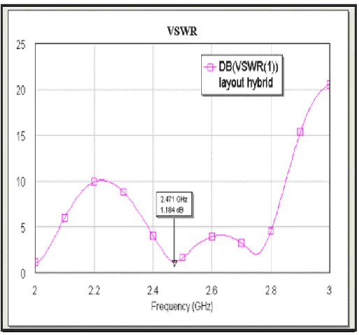
Figure 5: VSWR for the antenna
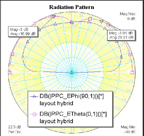
[image:5.612.178.435.380.620.2]© 2016, IRJET | Impact Factor value: 4.45 | ISO 9001:2008 Certified Journal | Page 296 Figure 6: Radiation pattern
From the radiation pattern, the normalized value of the radiation pattern will give half power beamwidth value. Half power beamwidth is a measurement of angular spread of the radiated energy. By adding the values at 3 dB, the half power beamwidth of the antenna can be obtained. From Figure 7, the values at 3dB are 16.99° and 28.91°. Thus, the half power beamwidth of this microstrip patch antenna is 45.9°.
Figure 7: Half power beamwidth
[image:6.612.182.430.416.650.2]INTERNATIONAL RESEARCH JOURNAL OF ENGINEERING AND TECHNOLOGY
(IRJET) E-ISSN: 2395 -0056
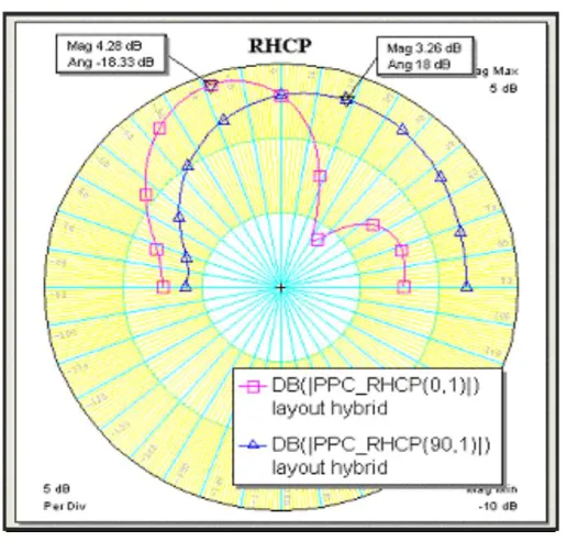
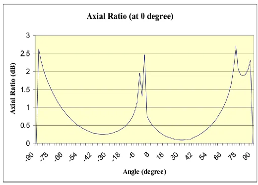
VOLUME:03ISSUE:06|JUNE-2016 WWW.IRJET.NET P-ISSN: 2395-0072© 2016, IRJET | Impact Factor value: 4.45 | ISO 9001:2008 Certified Journal | Page 297 To be able to obtain the axial ratio, the values of Left hand circular polarized (as shown in Figure 8) and values of Right hand circular polarized (as shown in Figure 9) are tabulated. By using Microsoft Excel software, the axial ratio is calculated. The formula of axial ratio is given as:
[image:7.612.44.454.127.630.2](2)
Figure 8: Left hand circular polarization
Figure 9: Right hand circular polarization
[image:7.612.178.436.426.672.2]© 2016, IRJET | Impact Factor value: 4.45 | ISO 9001:2008 Certified Journal | Page 298 Figure 10: Axial ratio for the microstrip antenna
IV.
C
ONCLUSIONThere is various type of microstrip antenna that is able to excite a circular polarization. For this project, dual – fed circular polarization microstrip antenna is chosen. The microstrip antenna is design to operate at 2.4 GHz frequency. The dual –fed circular polarization microstrip antenna is successfully implemented and fabricated. The microstrip antenna resonates at 2.47 GHz and gives a good return loss, which is -23.25 dB. This is a good value because only 0.47 % power is reflected and 99.53 % power is transmitted. The VSWR of the microstrip antenna is 1.2:1, which shows that the level of mismatched for the microstrip antenna is not very high. High VSWR means that the port is not properly matched. The bandwidth of this microstrip antenna is also good, which is 17.04 % and the maximum radiation occurs at -40° with gain of 4.28 dB. The microstrip antenna is said to be circular if the axial ratio is 0 dB. From the calculation of axial ratio, most of the angles give 0 dB value, thus prove that the microstrip antenna polarize circularly.
The results are obtained from simulation and measurement. Firstly all the vakues that obtained from the calculations for the width and length of dual fed cicularly polarization is tabulated.
Then from the simulation by Microwave Office software, the schematic diagram, as well as the 2D and 3D view of the dual –fed circular polarization microstrip antenna are shown. The values for return loss, bandwidths, VSWR are obtained and shown in this chapter, as well as the radiation pattern and axial ratio for this dual –fed circular polarization microstrip antenna. Finally, measurement is done and comparison between simulated and measured value is compared and contrasted.
REFERENCES
[1] Pozar, D. M.(1996). A Review of Aperture Coupled Microstrip Antennas:History, Operation, Development, and Applications,University of Massachusetts: Article review.
[2] Saed, R. A., and Khatun, S. (2005). Design of Microstrip AntennaforWLAN, Journal of Applied Sciences. 5 (1): 47 – 51 [3] Lu Wong, K (2003). Planar Antennas for Wireless Communications.Hoboken, N. J: John Wiley & Sons.
[4] Haider, S. (2003). Microstrip patch antennas for broadbandindoorwireless system. University of Auckland: Maters Thesis [5] Balanis, C. A. (1997). Antenna Theory, Analysis and design.2nded.Hoboken, N. J: John Wiley & Sons.
[6] Clarke, R. W. Lecture notes and lab scripts. University of Bradford
[7] Mohd. Kamal bin A. Rahim. Teaching Module, RF / MicrowaveandAntenna Design. UTM