© 2016, IRJET | Impact Factor value: 4.45 | ISO 9001:2008 Certified Journal
| Page 1985
BUCKLING ANALYSIS OF LAMINAR COMPOSITE PLATES WITH
CUTOUTS
Dilu Riswana C
1, Dr. Sabeena. M.V
21
P.G. Student, Department of Civil Engineering, AWH Engineering College, Kozhikode, Kerala, India
2Professor and Head, Department of Civil Engineering, AWH Engineering College, Kozhikode, Kerala, India
---***---Abstract -
Laminated composite plates are made up ofplates consisting of layers bonded together and made up of materials chemically different from each other but combined macroscopically. In structures, holes provided in laminated composite plate show reduction in strength, stiffness and inertia. The optimization and nonlinear behavior on the effect of various parameters on the buckling load of square and cylindrical laminated plates with and without cut-outs. Cutouts are necessary to serve the purpose of weight reduction, venting and attachments to other units for the cable to pass through are so on. The parameters considered are cut-out location, fiber orientation angle, length to thickness ratio, boundary condition and Young’s Modulus Ratio. The analyzed laminated plates are of carbon fiber reinforced composite materials. Laminated composite plate with circular cutout shows a decrease in buckling load than plates without cutout.
Key Words: Buckling Analysis, Finite Element Method, Circular Cutouts, Carbon Fibre, Laminated Composite Plate
1. INTRODUCTION
Composite laminated plates when loaded in compression are subjected to a type of behavior known as buckling.
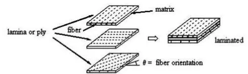
Composite material is composed of two or more materials and possesses the properties which could not have been achieved from any of its constituent materials alone. In such materials the main load bearing members are the fibers. The matrix has low modulus and high elongation and it provides flexibility to the structure, keeps the fibers in position and protects them from the external forces of the environment. A composite material is composed of two or more materials and offers a significant weight saving in structures in the view of high strength.
Fiber-reinforced composite materials for structural applications are made in the form of a thin layer, called lamina. A lamina is a macro unit of material. Fiber orientation in each lamina and stacking sequence of the layers can be chosen to achieve desired strength and stiffness for a specific application.Properties of composites are due to its constituent materials, their distribution and their orientation which altogether gives an unusual combination of properties.
Fig -1
: Laminated Composite Plate
[image:1.595.306.557.231.306.2]© 2016, IRJET | Impact Factor value: 4.45 | ISO 9001:2008 Certified Journal
| Page 1986
uniaxial compressive loads was carried out by Hsuan-Teh Huet al. [6]. Comparing with the linearized buckling loads of the skew plates, the nonlinear in-plane shear together with the failure criterion have significant influence on the ultimate loads of the composite laminate skew plates.
2. NUMERICAL ANALYSIS USING FINITE ELEMENT
METHOD
This work is to find buckling load factors of carbon fiber composite square and cylindrical plates using finite element analysis ANSYS 14.5 APDL. The plate has length L and thickness t with three different boundary conditions such as fixed, clamped and unclamped boundary conditions. The stacking sequence adopted is [00/900] and [00/900/00] hence
the number of layers are two and three respectively The analysis is done in the following cases:
Case1: The analysis is done by placing different center holes in the plate with same area. The shapes of central hole are circle, square, triangle, and star. The Nature of buckling load factor is studied.
Case2: Among these more efficient hole is adopted and nature of buckling load factor with respect to L/t ratio, and young’s modulus ratio with all three different boundary conditions for both two-layered and three layered plates is studied.
Case3: Further the work is extended to the analysis on cylindrical plates. The Nature of buckling load factor with respect to L/t ratio and young’s modulus ratio with all three different boundary conditions for both two-layered and three layered plates is studied.
Case4: From these more effective boundary condition is adopted for the analysis of effect of different ply orientations of plate on the buckling load.
3. ELEMENT DESCRIPTION
In this study, element type being used is SHELL281. This shell element is used for analyzing thin to moderately-thick shell structures. It is also used for layered applications for modeling laminated composite shells or sandwich construction. It is well-suited for large rotation, linear, and/or large strain nonlinear applications. The element has eight nodes with six degrees of freedom at each node: translations in the x, y, and z axes, and rotations about the x, y, and z axes. The eight-node nonlinear element S8R5 which is an element with five degrees of freedom per node is being used in analyses for cylindrical plates.
4. GEOMETRIC MODELLING
The length of square plate is varying from 500mm. Diameter of central hole is taken to be 50mm. Cylindrical Specimens are nominated as L500-R200. The numbers following L and R show the length and radius of the panel, respectively.
Table -1: Properties of carbon material
Young’s modulus (Pa)
E11=
1.397x10¹¹
E22=
1.139x10¹¹
E33=
1.139x10¹¹
Poisson’s
ratio
ν
12= 0.3236ν
23= 0.4610ν
13= 0.3236Rigidity modulus (Pa)
G12=
4.753x10⁹
G23=
3.898x10¹⁰
G13=
4.753x10⁹
The varying thicknesses
of the plate are 2mm, 2.5mm,
3mm and 3.5mm.
5. MODEL OF CARBON COMPOSITE PLATE
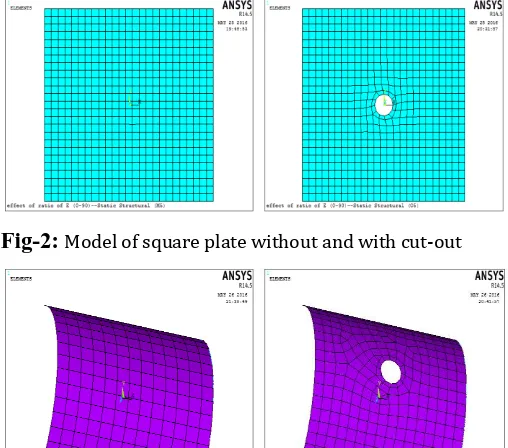
Fig-2:
Model of square plate without and with cut-outFig-3:
Model of cylindrical plate without and with cut-out5. RESULTS AND DISCUSSIONS
5.1 The Effect of Different Cutouts of Plate on the
Buckling Load
[image:2.595.308.562.333.557.2]© 2016, IRJET | Impact Factor value: 4.45 | ISO 9001:2008 Certified Journal
| Page 1987
Chart -1: Buckling load deformation graph of square plate
Chart -2: Buckling load deformation graph of cylindrical plate
The main aim is to find out the more efficient plate with cut-out to the buckling load. From these results, it is seen that plate with circular cut-out possesses more buckling load carrying capacity. It is because that it does not contain any corner points that causes stress concentrations. The analyses indicate that the variation of the buckling loads is very sensitive to the presence of cut-out. The buckling load generally decreases with presence of cut-out. Out of triangle, square and star cut-out, triangular cut-out possess more buckling load than square out and star out. Star cut-out shows the least buckling load carrying capacity, since star cut-out has got more corner points thanthe triangle and square cut-out. These variations of cut-outs are due to the variation in the stress concentration.
5.2 The Effect of Different Boundary conditions of
Plate on the Buckling Load
Chart-3 and Chart-4 shows the effect of the boundary conditions on the buckling load for square composite plate and cylindrical composite plate, respectively.
Chart -3: Comparison graph of square plate with holes
Chart -4: Comparison graph of cylindrical plate with holes
In this study, the laminated plates are evaluated at three different boundary conditions that exhibit distinct behavioral characteristics. The boundary conditions adopted are fixed, clamped and unclamped boundary conditions on the sides of the plates. Boundary conditions of composites have the strongest effect on the buckling load.
The dependence of the buckling load on the ply orientation for the unclamped, clamped and fixed boundary conditions was investigated and it was observed that the maximum buckling load for a given boundary conditions at (0/90/0) ply orientation. This indicates that more buckling load carrying capacity is possessed for plates with more number of layers.
© 2016, IRJET | Impact Factor value: 4.45 | ISO 9001:2008 Certified Journal
| Page 1988
5.3 Effect of Different Ply Orientations of Plate on
Buckling Load
The effect of different ply orientations of the plate under same boundary condition is studied in this section. Here the condition taken is fixed boundary condition. The different ply orientations taken in this section are (0/0/0), (0/30/0), (0/45/0), (0/90/0), (90/90/90) and (90/0/90). These are analysed and its effects are studied.
Chart -5: Buckling load deformation graph of plates with ply orientations
Chart -6: Buckling load deformation graph of cylindrical plates with ply orientations
As it is understood that the maximum load carrying load capacity is for the fixed boundary condition, here the fixed condition is being adopted as the boundary. These conditions are taken for both square and cylindrical laminated plate in this section. The load deformation graph of plates with different ply orientations is shown in the Chart-5 and Chart-6. This graph shows us a clear idea of buckling effect of plates under the loads. (90/0/90) ply angle shows the highest buckling load when compared to the other ply angles. (90/90/90) is the lowest buckling load carrying
ply orientation. Here we have done this study on laminated composite plate with central circular cut-out. It is because, our studies in above section revels that square laminated composite plate with central circular cut-out shows the good buckling load effect under cut-out plates.
6. CONCLUSIONS
This study considers the buckling response of laminated Composite plates with different boundary conditions. The laminated composite plates have varying aspect ratio, varying breadth to thickness b/t ratio, cut out shape and changing places of holes are considered. From the present analysis, the following conclusions are made:
The buckling load increases as L/t ratio decreases. Presence of cut-out lowers the buckling load. As the
surface area decreases in presence of cut-out, the load required to buckle the plate and deform its shape becomes less. Hence the buckling load decreases. As the number of layers increases, the buckling load also
increases. This is because as the number of layers increases, the interaction between each layer increases and therefore high amount of load is required to get the critical buckling load.
As EL/ET ratio increases, the buckling load also increases
The buckling load changes with change in its boundary condition. The highest value corresponds with the fixed boundary condition than unclamped and clamped boundary conditions.
Buckling load changes with change of cut-out shapes as well. For circular cut-outs, the buckling load comes out to be the maximum. And for star cut-outs of same dimension, the buckling load is minimum.
REFERENCES
[1] Parth Bhavsar, Prof. Krunal Shah, Prof. Sankalp Bhatia,
“An overview of buckling analysis of single ply composite plate with cut-outs”. International Journal of Engineering Research and General Science Volume 2, Issue 5, August-September, 2014 ISSN 2091-2730
[2] Joshi A, Ravinder Reddy P, Krishnareddy V.N,
Ch.V.Sushma, “Buckling analysis of thin carbon/epoxy plate with circular cut-outs under biaxial compression by using fea”. IJRET: International Journal of Research in Engineering and Technology, (2013) eISSN: 2319-1163 | pISSN: 2321-7308
[3] Nagendra Singh Gaira, Nagendra Kumar Mourya and
Rakesh Kumar Yadav, “Linear buckling analysis laminar composite plate”. International journal of engineering science and advanced technology(2012) volume 2, Issue :4
[4] Hamidreza Allahbakhsh and Ali Dadrasi, “Buckling
Analysis of laminated composite panel with Elliptical cut-out subjected to axial compression”. Volume 2012, Article ID 171953, 10 pages.
[5] Bucket Okutan Baba (2007), “Buckling Behaviour of
© 2016, IRJET | Impact Factor value: 4.45 | ISO 9001:2008 Certified Journal
| Page 1989
[6] Hsuan-Teh Hu, Chia-Hao Yang, Fu-Ming Lin, “Buckling