© 2015, IRJET ISO 9001:2008 Certified Journal Page 796
DESIGN OF 8X8 WALLACE MULTIPLIER USING
MUX BASED FULL ADDER WITH COMPRESSOR
C.Dhivya1, M.Thiruppathi2, R.Sowmiya 3
1
M.E., VLSI Design, Vivekanandha College of Engineering for Women, Tamilnadu.
2Assistant Professor, Department of ECE, Vivekanandha College of Engineering for Women,Tamilnadu. 3M.E., Applied Electronics, Vivekanandha College of Engineering for Women, Tamilnadu.
---Abstract Multiplier is an important element in many
signal processing systems. It is an area consuming and slowest element, its performance will determines the performance of a system itself. So that it is necessary to design an efficient multiplier in terms of satisfying the important parameters of low power, area and speed. This paper presents the comparison of two multipliers namely Wallace multiplier and compressor based Wallace multiplier. The results of these two multipliers were compared and shows that the compressor based Wallace multiplier will give better performance in terms of reduced area. Simulation of 8x8 multiplier is carried out using Xilinx 10.1.
Key words AND gate, 5:2 compressor, Full adder,
Half adder, Wallace multiplier.
1. INTRODUCTION
Nowadays designing a multiplier with satisfying all the parameters of area, power and speed is a challenging one. Many researches has been made to obtain an efficient multiplier, but still there is a draw backs. Multiplier will plays a major role in Digital signal processing, VLSI signal processing etc[1]. Many of the DSP applications such as mobile phones, MP3 player, digital video recorder, and so on is mainly intensive and
it test the limits of their battery life. In many of the signal processing applications, rounded product is needed, because the word size will increase. To avoid this problem a multiplier is to be designed with less area. Nowadays peoples are not interested in large size products because it is not portable easily and also not comfortable to use. If the area will reduced i.e., the number of transistor count will be reduced then automatically the speed will also gets reduced. The designer wants to design a multiplier with rectifying all these problems. This paper will give a better trade off between these two parameters.
© 2015, IRJET ISO 9001:2008 Certified Journal Page 797 (CSA) is used for the final addition stage, the 4:1
multiplexer is replaced with 8:1 multiplexer to improve the speed performance of the multiplier. The proposed architecture will give better performance than the previous method.
2. WALLACE TREE MULTIPLIER
A Wallace tree is an efficient hardware implementation of a digital circuit that multiplies two integers, devised by Australian Computer Scientist Chris Wallace in 1964.
The Wallace tree has three steps:
Multiply (that is - AND) each bit of one of the arguments, by each bit of the other, yielding results. Depending on position of the multiplied bits, the wires carry different weights.
Reduce the number of partial products to two by layers of full and half adders.
Group the wires in two numbers, and add them with a conventional adder.
The second phase works as follows. As long as there are three or more wires with the same weight add a following layer:
Take any three wires with the same weights
and input them into a full adder. The result will be an output wire of the same weight and an output wire with a higher weight for each three input wires.
If there are two wires of the same weight left, input them into a half adder.
If there is just one wire left, connect it to the next layer.
The benefit of Wallace tree is that there are only
reduction layers shown in Fig 1. Each
layer has propagation delay. As making the
partial products is and the final addition is
, the multiplication is only ,
not much slower than addition (however, much more expensive in the gate count). Naively adding partial products with regular adders would require
time. These computations only
consider gate delays and don't deal with wire delays, which can also be very substantial.
Fig-1: Wallace reduction for an 8x8 multiplier
3. IMPLEMENTATION OF FULL ADDER USING 8:1 MUX
© 2015, IRJET ISO 9001:2008 Certified Journal Page 798 with the existing method.The logic diagram of the
full adder using 8:1 MUX is shown in fig 2.
Fig- 2: Logic diagram of full adder using 8:1 MUX
Table- 1: Truth table of full adder
In 8:1 multiplexer there are 8 input ports and one output port. There are also 3 digital inputs that select one of the 8 input port signals to be sent to the output, the particular one selected depending on the binary code at the 3 select inputs.
Multiplexers come in both purely digital forms (made entirely of gates, that reproduce the inputs as new binary output signals) and analog forms (that are made of analog switches that simply connect one of the inputs to the output). In the Wallace architecture this MUX concept is implemented, the multiplier will becomes modified MUX based multiplier, this will increase the speed performance of the multiplier.
4. CARRY SELECT ADDER
Among many types of adder carry select adder will give the better performance in terms of low power VLSI [2]. So in this multiplier design carry select adder will be used. The first two steps of the Wallace tree multiplier i.e., partial product generation and partial product reduction is explained in fig 1. After the reduction stage the final stage is the partial product addition stage, for addition process carry select adder is used in the multiplier design [5].
© 2015, IRJET ISO 9001:2008 Certified Journal Page 799 calculated, the correct sum, as well as the correct
[image:4.612.335.558.150.414.2]carry, is then selected with the multiplexer once the correct carry is known.
Fig -3: Basic building blocks of carry select adder
Fig 3 is the basic building block of a carry-select adder, where the block size is 4. Two 4-bit ripple carry adders are multiplexed together, where the resulting carry and sum bits are selected by the carry-in. Since one ripple carry adder assumes a carry-in of 0, and the other assumes a carry-in of 1, selecting which adder had the correct assumption via the actual carry-in yields the desired result. The number of full adders used in the carry select adder(CSA) is replaced by using 5:2 compressor.
5. COMPRESSOR BASED WALLACE MULTIPLIER
The partial product reduction stage consist of many number of full adders. The delay in the Wallace tree multiplier will be reduced by
decreasing the total number of adders present in the partial product reduction stage [7].
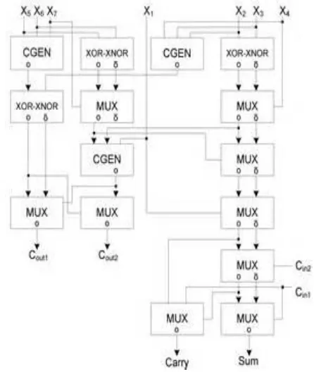
Fig- 4: MUX based 5:2 compressor design
The total number of full adders used in the partial product reduction stage is compressed by using 5:2 compressor.
5.1 5:2 COMPRESSOR
[image:4.612.46.273.167.356.2]© 2015, IRJET ISO 9001:2008 Certified Journal Page 800 Fig -5: 5:2 compressor block
The above diagram is the block diagram of 5:2 compressor.
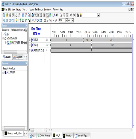
6. SIMULATION RESULT
[image:5.612.339.601.135.408.2]The simulation of 8x8 multiplier is performed by using Xilinx 10.1 ISE tool. The input and the output results of the 8x8 wallace multiplier is given in the following simulation results.
Fig- 6: Input block of the 8x8 multiplier
Fig -7: Output block of the 8x8 multiplier
7. RESULT ANALYSIS
[image:5.612.51.278.433.664.2]© 2015, IRJET ISO 9001:2008 Certified Journal Page 801
Table- 2: Design Summary Of The Multiplier
Table- 3: Synthesis Report Of The Multiplier
Table- 4: Comparison Of Existing And Proposed Method
Types of Multiplier Slices LUT Delay
Wallace multiplier with regular full adder
87 163 17.223
Wallace multiplier with MUX based full adder
84 155 17.789
Compressor based
Wallace multiplier
81 140 6.216
8. CONCLUSION
This paper provides the comparison between the Wallace multiplier with MUX based full adder and
the compressor based Wallace multiplier.
© 2015, IRJET ISO 9001:2008 Certified Journal Page 802 FUTURE EXTENSION
The 8x8 multiplier can be further
extended up to 32 bit, 64 bit.
Multiplication algorithms may be
used.
The simulation may also be
performed in some other tools.
ACKNOWLEDGEMENT
Our thanks to the experts who have contributed towards development of this paper. We extend our sincere thanks to all the faculty and staff members of Electronics and Communication Engineering department of the Vivekanandha College of Engineering for Women, for their valuable suggestions and help throughout our paper work. We also thank our friends and family members for their support towards the completion of the project work.
REFERENCES
[1] Dakupati. Ravi Shankar and Shaik Ashraf Ali, “Design of Wallace Tree Multiplier by Sklansky Adder. International Journal of EngineeringResearch and Applications (IJERA) ISSN: 2248- 9622 www.ijera.com .Vol. 3, Issue 1, January - February 2013, pp.1036-1040.
[2] Suresh R.Rijal, Ms.Sharda and G. Mungale, “Design and Implementation of 8X8 Truncated Multiplier on FPGA”. International Journal of Scientific and Research Publications, Volume 3, Issue 3, March 2013 .ISSN 2250-3153.
[3] Rais, M.H., 2009. FPGA design and implementation of fixed width standard and truncated 6×6-bitmultipliers : Proceedings of the 4th IEEE International Design and Test Workshop, Nov. 15-17, IEEE Xplore Press, Riyadh, Saudi Arabia, and pp: 1- 4.DOI:10.1109/IDT.2009.5404081.
[4] S.Rajaram, Mrs.K.Vanithamani,“Improvement of
Wallace multipliers using Parallel prefix adders” Proceedings of 2011 International Conference on Signal Processing, Communication, Computing and Networking Technologies (ICSCCN 2011).
[5] Chris Y.H. Lee, Lo Hai Hiung, Sean W.F. Lee, nor Hisham Hamid, “A Performance Comparison Study on Multiplier Designs”, Department of Electrical and Electronic Engineering Universiti Teknologi PETRONAS, Bandar Seri Iskandar.
[6] Tronoh, Perak Darul Ridzuan, MalaysiaB.Ramkumar, Harish M Kittur, P.Mahesh Kannan, “ASIC Implementation of Modified Faster Carry Save Adder”, European Journal of Scientific Research, ISSN 1450-216X Vol.42 No.1 (2010), pp.53-58.
[7] Ron S. Waters and Earl E. Swartzlander, “A Reduced Complexity Wallace Multiplier Reduction. IEEE Transactions On Computers, Vol. 59, No. 8, August 2010. Published by the IEEE Computer Society.
[8] W.J. Townsend, E.E. Swartzlander Jr., and J.A. Abraham, “A Comparison of Dadda and Wallace Multiplier Delays,” Proc. SPIE, Advanced Signal Processing Algorithms, Architectures, and Implementations XIII, pp. 552-560, 2003.
[9] R.S. Waters, MATLAB based Wallace and Modified
Wallace Multiplier Generator Programs,
http:\\ronwaters.com\, 2007
[10] C.S. Wallace, “A Suggestion for a Fast Multiplier,” IEEE Trans. Electronic Computers,vol. 13, no. 1, pp. 14-17, Feb. 1964.
[11] King, E. J. and E. E. Swartzlander, Jr., 1997. “Data -Dependent Truncation Scheme for Parallel Multipliers”, In Proceedings 31st Asilomar Conference on Signals, Systems, and Computers,Vol. 2, pp. 1178–1182, Pacific Grove, CA.
[12] M. J. Schulte and E. E. Swartzlander, Jr., “Truncated multiplication with correction constant,” in ieeexplore.ieee.org ›VLSI Signal Processing, VI, pp. 388–396, 1993.
© 2015, IRJET ISO 9001:2008 Certified Journal Page 803
[14] A. Habibi and P.A. Wintz. “Fast Multipliers,” IEEE Trans. on Computers, vol. 19, pp. 153-157, 1970.
[15] W.J. Townsend, E.E. Swartzlander, Jr. and J.A. Abraham. “A Comparison of Dadda and Wallace Multiplier Delays”, in SPIE Adv. Signal Proc. Algorithms,Architectures and Implementations XIII, pp. 552-560, 2003.
[16] S. Shah, A.J. Al-Khalili and D. Al-Khalili. “Comparison of 32-bit Multipliers for Various Performance Measures,” in
The 12th International Conference on Microelectronics, pp. 75-80, 2000.
[17] K.C. Bickerstaff and E.E. Swartzlander, Jr. “Analysis of Column Compression Multipliers,” in 15th IEEE Symp. on Computer Arithmetic, pp. 33-39, 2001.
[18] J.M. Rabaey, A. Chandrakasan and B. Nikolic. “Design Synthesis,” in Digital Integrated Circuits, 2nd ed., New Jersey: Pearson Education Inc., 2003, pp. 397, 435-439.
[19] Mi Lu. “Modular Structure of Large Multiplier,” in Arithmetic and Logic in Computer Systems, 1st ed, New Jersey: John Wiley & Sons, Inc., 2004, pp. 120-122.
[20] C.S. Wallace. “A Suggestion for a Fast Multiplier,”