© 2016, IRJET | Impact Factor value: 4.45 | ISO 9001:2008 Certified Journal | Page 839
APPLICATION OF SUPERCONDUCTING MAGNETIC ENERGY STORAGE
(SMES) SYSTEM IN AUTOMATIC GENERATION CONTROL
S. Teja Srinivas, Dr. A. Rama Devi
1
P.G student, EEE, V.R. Siddhartha Engineering College, Andhra Pradesh, India-520007
2Professor, EEE Department, V.R. Siddhartha Engineering College, Andhra Pradesh, India-520007
---***---Abstract –
The objective of the paper is to examine theperformance of the Automatic Generation Control (AGC) with the application of Superconducting Magnetic Energy Storage (SMES) system unit for multi area interconnected power system. Load Frequency Control (LFC) is a part of AGC plays a vital role in power sector. The purpose of AGC is to maintain system frequency to a specified nominal value, maintain generation of individual unit’s and to keep the tie-line power between different units at the most economical value.
The simulation results using MATLAB/SIMULINK show that Load Frequency Control (LFC) in a multi area interconnected power system with SMES unit are considerably improved in terms of overshoot time and settling time when compared to that of the system without SMES unit.
Key Words:
Superconducting Magnetic Energy Storage (SMES)
System, Load frequency control (LFC), Area control
Error (ACE).
1. Introduction
Power system is a typical network that consists of several generating units and transmission, distribution networks and consumer loads. In order to operate the system in stable manner the system constraints such as frequency and voltage must be maintained at the pre-specified limits. Due to irregular variation in load demand the power system network will not be able to with stand those variations and it is impossible to keep the power balance between the consumer and generating side. These power imbalances will results on the variations in the frequency and tie-line power. At present most of the systems are interconnected because of advantages like the economical exchange of power, reliability, maintaining the coordination schedules. If there is a sudden variation in load it will affect the frequency deviations and tie-line powers among the interconnected areas [16]. The variation in frequency depends on the active power and variation in voltage depends on the reactive power. The control referred to the active power and frequency is Load Frequency Control (LFC).
Many controllers (Such as PI controller, PID controller) are used to bring back the system in to normal state by reducing the variations.
In general there are two types of energy storage techniques available. They are 1.Direct 2.Indirect based on the type of usage.
In direct type energy is stored in magnetic and electro static fields whereas in indirect type energy is stored by artificially created systems. The commonly used energy storage systems are flywheels, batteries, pumped hydro, super capacitor, and super conducting magnetic energy storage systems. Each system has its own advantages in their application fields but by considering all the systems superconducting magnetic energy storage (SMES) has a peculiar advantage i...e, in all the energy storage systems conversion of energy is compulsory but in SMES systems will store the energy inductively and there is no need of conversion of energy.
2 Superconducting Magnetic Energy Storage (SMES) Systems
The interconnection of regional power systems and the integration of renewable energy generation make the stability of a large-scale power system increasingly important and challenging. To enhance power system stability, various types of controllers are employed for power systems, such as power system stabilizers (PSSs) and supplementary damping controllers of the flexible AC transmission system (FACTS) devices and Superconducting magnetic energy storage (SMES) systems also. As superconducting magnetic energy storage (SMES) is capable of commutating both active and reactive power with the grid rapidly and independently, it has better performance than FACTS in terms of damping improvement. These SMES systems are also used for the improvement of power quality problems that are caused in the electrical grid ,such as load leveling, frequency regulation and stabilization of transmission system and etc..,.
© 2016, IRJET | Impact Factor value: 4.45 | ISO 9001:2008 Certified Journal | Page 840
is that once the superconducting coil is charged, thecurrent will not decay and the magnetic energy can be stored indefinitely. This stored energy can be released back into the electric network by simply discharging the coil.
A Superconducting Magnetic Energy Storage (SMES) system stores the energy in its magnetic field produced by the flow of direct current in a coil made of superconducting materials (e.g. Nb-Ti at 4.2K) which is cryogenically brought down to a temperature below its critical temperature using liquid form of Helium (He) or liquid form of Nitrogen (N2).
The relation between the inductively energy stored and the current flowing in the superconductor is given by the Equation.
(1)
Where E=Energy stored, L=Inductance, I=Direct current. The above equation can also be written as inductively energy stored and power rated will also give the relation as:
(2)
P = (3)
As per the IEEE SMES is “A superconducting magnetic energy storage device containing power electronic converters that rapidly injects or absorbs real or reactive power and dynamically controls power flow in an AC system”.
Among all the components of the SMES system the PCS (power conditioning system) plays the major role [19]. The main function of the PCS is to interface grid and the superconducting coil. This is aimed for the two processes.
1. It will convert the AC power to DC power
2. It will efficiently charge/discharge the Superconducting coil.
The PCS mainly consists of the power electronic devices and FACTS controllers.
[image:2.595.310.569.183.363.2]In the design of power conditioning system of the SMES unit there are three types of topologies namely,1.Thyristor controlled, 2.Voltage source controlled ,3.Current source controlled converters[1]. Among all the three converter topologies current source controlled converter is preferred than the other converters.
Figure 1: Current Source Converter based SMES
3. SYSTEM CONSIDERED
[image:2.595.39.285.617.739.2]A multi area power system contains areas of same or different generating units that are interconnected by tie-lines or transmission tie-lines [3]. The AGC system in an interconnected power system should control the interchange power with the other control areas as well as control the area frequency.
Figure 2: Block diagram of AGC for a two-area
Interconnected system
Practically several generating units operate in parallel in the same area [15]. For analysis sake an equivalent generator will be used to represent each area. If a number of generating units operating in parallel then equivalent of generator inertia constant (Heq), frequency sensitive load
coefficient (Deq), and frequency bias factor (Beq) can be
represented as follows.
∑ (4) ∑ (5)
∑ ∑ (6)
4. CONFIGURATION AND WORKING
© 2016, IRJET | Impact Factor value: 4.45 | ISO 9001:2008 Certified Journal | Page 841
the transfer of energy between the superconducting coil [image:3.595.38.288.112.295.2]and the power system.
Figure 3: Block diagram of SMES Unit
During the typical operation the superconducting inductor charging is done up to its specific value by the AC line. If charging is over, it will conduct current without any loss, because of operating the coil at low temperature. If unexpected augment in load, happens the energy stored until will be given back to AC system by the converter in the form of AC current [6]. With the operation of governor and other control mechanisms the entire system will be shifted to recent stability condition, then the current in the coil will be kept to the primary value. In the same way, due to the unexpected load drops, the charging of the coil is done to its complete value, by grasping small fraction of surplus energy present in the system. So, that system will regain the steady state, the absorbed surplus energy is lost and the coil current will be returned to the original value. The converter firing angle control will provide the inductor DC voltage to vary constantly within positive and negative values for specific periods. Initially by applying a small positive voltage the inductor is charged to its rated current Id0.If it attains the rated value, by using
the superconducting property of the coil the inductor voltage is reduced to zero in order to keep the current at constant value. By neglecting the converter and transformer losses, the DC voltage of the inductor is:
(7) Where Ed is DC voltage applied to the inductor (kV), α is
firing angle degree (°), Id is inductor current
(kA).Commutating equivalent resistance (ohm (Ω)) and Vd0 is maximum circuit bridge voltage (kV). The Charging
and discharging of SMES unit are controlled through change of commutation angle α.
If α<900 converter is operating in rectifier mode
(Charging)
If α>900 converter is operating in inverter mode
(Discharging).
For the Load frequency control problem, by sensing the area control error signal superconducting inductor DC voltage is continuously controlled. In general power
system, voltage deviation of inductor in SMES unit of each area is based on ACE of that particular area. The current variation in SMES control loop is given as a negative feedback. From that the steady state value of the SMES is attained by the current variable. When there is a small variation in load, the current deviation is provided by the feedback. So, for the following disturbance the value of current have to regain its precise value rapidly in order to operate for the immediate disturbance in load. Figure 4 represents the SMES unit control diagram. The following are the necessary equations in laplace transform of voltage and current variations of inductor in SMES unit are:
[ ]
(8)
[image:3.595.309.560.236.429.2](9)
Figure 4: Control Unit of SMES system
Where is incremental variation in voltage of converter (kV), is the Current incremental variation in SMES (kA), is feedback gain of ΔIdi (kV/kA), time delay of converter (sec), KSMES is gain constant (kV/unit ACE) and L is coil inductance (H). The divergence in the real power of inductor with respect to time in SMES unit is represented as:
(10) The above value is supposed to be positive for exchange of power from ac line to dc. The stored energy with respect to time in SMES unit is:
(11)
5. OBJECTIVE FUNCTION
The control configuration for multi area power system is depicted in fig. 2. The control strategy depends up on tie-line bias control. The error input to the controllers are the respective area control errors (ACE) given by
ACEi =∆Ptie, I + Bi∆Fi (12) Control input to the power system is obtained by use of PID controller together with the area control errors ACE1 and ACE2. The control input of the power system u1 and u2 are the output of the controllers and these are obtained as
© 2016, IRJET | Impact Factor value: 4.45 | ISO 9001:2008 Certified Journal | Page 842
on area control error a performance index J can be definedas [14]:
∫ ∑ (14)
6. MULTI AREA POWER SYSTEMS
In this paper for the LFC analysis a multi area interconnected power system is taken. In multi area power system area-1 and area-2 consists of thermal plants of non-reheat type, reheat type respectively and area-3 consists of hydro plant and area-4 consists of gas plant. For an interconnected system, each area connected to others via tie line which is the basis for power exchange between them. When there is change in power in one area, which will be meeting by the raise in generation in every associated area with modify in the tie line power and a decrease in frequency [17]. But in normal working state of the power system that is the demand of each area will be satisfied at a normal frequency and each area will absorb its own load changes. For each area there will be area control error (ACE) and this area control error (ACE) is reduced to zero by every individual area. The ACE of each area is the linear combination of the frequency and tie line
error, i.e. ACE = Frequency error + Tie line error. In order to implement this multi area system it must have
the system data for operating. Therefore the system data is given in the following table 2.For the implementation of the SMES in the present system it must also have the system data and table 1 show the data for the SMES unit.
7. SIMULATION RESULTS
[image:4.595.297.566.87.590.2]A multi-area interconnected power system is taken for LFC analysis. In multi-area power system area-1 consists of thermal plant, area-2 consists of thermal with reheat, area-3 consists of hydro plant and area-4 consists of gas plant. Simulation model of the proposed system with PID-SMES controller is shown in Figures 5.
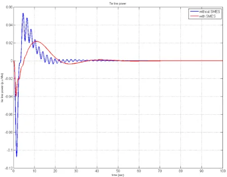
Table 1: System Data of SMES coil
Table 2: System data for two area thermal non-reheat
Systems
Data Value
Control loop gain 100 kV/unit Mw converter time constant 0.03sec
feedback gain 0.2 kV/kA Inductor current deviation
4.5 KA
Inductance of SMES L 2.65 H
Data Value
Non-Reheat thermal unit
Speed governor time constant( ) 0.08 sec
Turbine time constant ( ) 0.3 sec
deviation coefficients of governor ( )
2.4 Hz/p .u. MW
Reheat thermal unit
governor time constant( ) 0.08 sec
Turbine time constant ( ) 0.3 sec
deviation coefficients of governor
)
2.4 Hz/p .u. MW
Low pressure reheat time ( ) 0.5 sec
High pressure reheat time( ) 10 sec
Hydro turbine Speed governor time constant
( )
4.9s
Transient droop time constant ( )
28.749s
Main servo time constant ( ) 0.2s
Water time constant ( ) 1.1s
Speed governor regulation ( ) 2.4HZ/p .u .MW
Gas turbine Speed governor lead time
constants ( )
Speed governor lag time constants ( )
0.6 sec 1.1 sec
Valve position constants ( ) Valve position constants ( )
0.049 sec 1 sec
Fuel time constants ( ) 0.239s
Combustion reaction time delay ( )
0.01 sec
Compressor discharge volume time constant ( )
0.2 sec
Speed governor regulation
parameter ( ) 2.4 Hz/p .u. MW
Power system Frequency bias constants
(B1,B2,B3,B4) 0.425puMW/Hz
a=2*pi*T12=2*pi*T23
=2*pi*T34=2*pi*T41 0.544
load model gain (Kps) 120HZ/pu MW
load time constant (Tps) 20s
© 2016, IRJET | Impact Factor value: 4.45 | ISO 9001:2008 Certified Journal | Page 843
Figure 5: Simulation diagram of multi area system
Figure 6: Frequency deviation in thermal non-re-heat
[image:5.595.326.527.107.288.2]System
Figure 7: Frequency deviation in thermal re-heat system
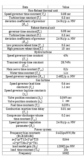
[image:5.595.328.536.320.502.2]Figure 8: Frequency deviation in hydro turbine system
[image:5.595.327.528.533.706.2]© 2016, IRJET | Impact Factor value: 4.45 | ISO 9001:2008 Certified Journal | Page 844
Figure 10: Tie line power deviation in thermal non-
re- heat system
Figure 11: Tie line power deviation in thermal re-heat
system
Figure 12: Tie line power deviation in hydro turbine
[image:6.595.326.534.107.281.2]system
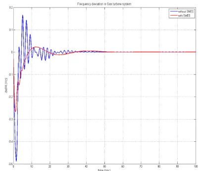
Figure 13: Tie line power deviation in gas turbine system
8. CONCLUSION
In this paper, the implementation of the Superconducting Magnetic Energy Storage (SMES) System is carried out in the multi area system consisting of a thermal non-reheat, thermal reheat, hydro, gas turbine systems. But, by observing the performance of the SMES after placing in the AGC problem it has mainly reduced the oscillations in the system and as well as the transient response (Over-Shoot, Settling Time) characteristics. Placing of SMES plays a vital role. A small capacity of the SMES system will minimize the control error, frequency deviation as well as the exchange of tie-line power. The improvement in the LFC is done only with the operation of the SMES units in all areas the frequency deviation and tie-line power deviations along with oscillations in the system are enhanced.
REFERENCES
[1] Md Hosan and Roger A. Dougal-An Overview of SMES Applications in Power and Energy Systems, IEEE Trans. Sustainable Energy,Vol.1,no.1,April 2008. [2] V.Rajaguru,R.Sastry,V.Shanmugam,-Apllication of
Energy storage Units in Power System for Improving the system dynamics .I Journal of Scientific
engineering and Technology
Research,Vol.03.Issue.08,May2014,pp.1394-1400. [3] Hadi Saadat, “Power System Analysis”, Mc Graw- Hill,
New Delhi, 2002.
[4] R.J. Abraham, D. Das, and A. Patra, ―Automatic generation control of an interconnected hydrothermal power system considering superconducting magnetic energy storage, Elect. Power Energy Syst., Vol. 29, 2007, pp. 571-579.
[5] P.S.R Murthy ,”Power System Analysis”, B S publications, second edition.
[image:6.595.62.275.304.481.2] [image:6.595.58.282.534.709.2]© 2016, IRJET | Impact Factor value: 4.45 | ISO 9001:2008 Certified Journal | Page 845
dynamics, IEEE Trans. Power Systems, vol.7, no.3,1992, pp.1266-1272.
[7] Prabha kundur, ”Power System Stability and Control” ,Power system Engineering Series, EPRI, Tata Mc Graw Hill 1st Edition.
[8] S. Ganapathy, and S. Velusami, “Design of MOEA based decentralized load frequency controllers for interconnected power systems with non-linearities and SMES unit “International Journal of Computer and Electrical Engineering, Vol. 2, No. 1, February, 2010. [9] Nanda, M.L.Kothari, and P. S. Satsangi, "Automatic
generation control of an interconnected hydrothermal system in continuous and discrete modes considering generation rate constraints," Proc. Inst.Elect. Eng., vol. 130, pp. 17-27, Jan. 1983.
[10] M. L. Kothari, P. S. Satsangi, and Nanda, "Sampled data automatic generation control of interconnected reheat thermal systems considering generation rate constraints," IEEE Trans. Power App. Syst., vol. PAS-100, no. 5, pp. 2334-2342, May 1981.
[11] L P Kumar, and D.P. Kothari, "Recent philosophies of automatic generation control strategies in power systems," IEEE Trans. Power systems, vol. 20, pp. 346 - 357, Feb. 2005.
[12] S. C. Tripathy, G. S. Hope and 0. P. Malik, “Optimization of Load Frequency Parameters for Power system with Reheat Steam Turbines and Governor Dead-Band Nonlinearity”, IEEProc. Vol.129, Pt. C, No. 1,pp. 10-16, 1982.
[13] R.J. Abraham, D. Das, and A. Patra, ―Damping oscillations in tie-line power and Area frequencies in a thermal power system with SMES-TCPS combination.
J.Electrical systems, 2011,pp.71-80.
[14] I.J.Nagrath, D.P.Kothari, “Modern Power System Analysis”, BSP, Hyderabad, 2002.
[15] S.K. Sinha, Dr. R Prasad and Dr. R. N. Patel,” Design of optimal and integral controllers for AGC of two area interconnected power system” XXXII National systems conference, Nsc 2008, December 17-19, 2008.
[16] J.Nanda, and B.L.Kaul, ―Automatic generation control of an interconnected power system, IEE Proc., Vol. 125, No. 5, May 1978, pp. 385-390.
[17] J. Nanda, Fellow, S. Mishra, P. G. Mishra, and K.V. Sajith,”A novel classical controller for automatic generation control in thermal and hydro power systems” IEEE Proc. C, vol.138, No.5,Sep 2008.
[18] J. X. Xin, Z. G. Wang, Y. G. Guo, and J. G. Zhu, High temperature superconductingenergy storage techniques, Journal of the Japan Society of Applied Electromagnetics &Mechanics, Volume 15(2007). [19] R. Gupta, N.K. Sharma, P. Tiwari, A. Gupta, N. Nigam