© 2016, IRJET | Impact Factor value: 4.45 | ISO 9001:2008 Certified Journal
| Page 943
Active Power Filter For Power Quality Improvement
Ankit Saxena
1, Mr. Gunjan Gupta
2PG (Student), Department of Electronics and Communication Engineering, Invertis University, Bareilly, Uttar Pradesh,
India
1Assistant Professor, Department of Electronics and Communication Engineering, Invertis University, Bareilly, Uttar
Pradesh, India
2Abstract-
This paper tells the contamination issues created in power systems due to the non-linear features and fast changing of power electronic equipment. Power quality issues are turning stronger because sensitive equipment will be sorer for market competition reasons, equipment will continue contaminating the system more and more due to cost increase caused by the built-in competition and sometimes for lack of enforced regulations. Active power filter have been developed over the year to solve these problems to improve power quality. Among which Shunt active power filter (SAPF) is used to control the load current harmonics and reactive power compensation. In this work both PI controllers based Fuzzy Logic checked three-phase SAPF to pay tones and reactive power by non-linear load to improve power quality is enforced for three-phased three wire systems. Fuzzy controller is based on linguistic description and does not require a mathematical model of the system. A MATLAB program has been formulated to stimulate the system operation. Various simulation results are demonstrated under steady state considerations and performance of fuzzy and PI controllers is equated. PWM pattern generation is based on carrier less hysteresis based current control to obtain the switching indicates to the voltage sourced PWM converter.Keywords-
Active power filters, PWM, harmonicscompensation, power factor correction, power quality.
© 2016, IRJET | Impact Factor value: 4.45 | ISO 9001:2008 Certified Journal
| Page 944
devices, which have the ability to attenuate the issues created by PE, on the other hand.
the next few years. Hence it is very important to overcome these undesirable features.
Classically, shunt passive filters, consist of tuned LC filters and/or high passive filters are used to suppress the harmonics and power capacitors are employed to improve the power factor. But they have the limitations of fixed compensation, large size and can also exile resonance conditions.
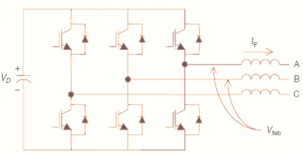
[image:2.612.317.539.404.550.2]Active power filters are now seen as a viable alternative over the classical passive filters, to compensate harmonics and reactive power requirement of the non-linear loads. The objective of the active filtering is to solve these problems by combining with a much-reduced rating of the necessary passive components.
Figure 1.1.Voltage source converter topology for active filters
Most of the active power filter topologies use voltage source converters, which have a voltage source at the dc bus, usually a capacitor, as an energy storage device. This topology, shown in Figure 1.1, converts a dc voltage into an ac voltage by appropriately gating the power semiconductor switches. Although a single pulse for each half cycle can be applied to synthesize an ac voltage, for most applications requiring dynamic performance, pulse width modulation (PWM) is the most commonly used today. PWM techniques applied to a
voltage source inverter consist of chopping the dc bus voltage to produce an ac voltage of an arbitrary waveform. There are a large number of PWM techniques available to synthesize sinusoidal patterns or any arbitrary pattern. With PWM techniques, the ac output of the filter can be controlled as a current or voltage source device.
Figure 1.2 shows the way PWM works by means of one of the simplest and most common techniques: the triangular carrier technique. It forces the output voltage v
a over a switching
cycle, defined by the carrier period of V
car, to be equal to the
average amplitude of the modulating wave V
a ref. The
resulting voltages for a sinusoidal modulation wave contain a sinusoidal fundamental component V
a(1) and harmonics of
unwanted components. These unwanted components can be minimized using a frequency carrier as high as possible, but this depends on the maximum switching frequency of the semiconductors (IGBTs, GTOs, or IGCTs).
[image:2.612.38.254.429.540.2]© 2016, IRJET | Impact Factor value: 4.45 | ISO 9001:2008 Certified Journal
| Page 945
power filter using three different modulation techniques for current-source inverters. These three techniques are periodical sampling (PS), hysteresis band (HB), and triangular carrier (TC). The PS method switches the power transistors of the active filter during the transitions of a square wave clock of fixed frequency: the sampling frequency. The HB method switches the transistors when the error exceeds a fixed magnitude: the hysteresis band. The TC method compares the output current error with a fixed amplitude and fixed triangular wave: the triangular carrier. Figure 1.3 shows that the HB method is the best for this particular waveform and application because it follows more accurately the current reference of the filter. When sinusoidal waves are required, the TC method has been demonstrated to be better.
Figure.1.3. Current waveforms obtained using different modulation techniques for an active power filter: (a) PS method, (b) HB method, (c) TC method
1.1 Power Quality
-
The PQ issue is defined as “any occurrence manifested in voltage, current, or frequency deviations that results in damage, upset, failure, or mis-operation of end-use equipment.” Almost all PQ issues are closely related with PE in almost every aspect of commercial, domestic, and industrial application. Equipment using power electronic devise are residential appliances like TVs, PCs etc. business and office equipment like copiers, printers etc. industrial equipment like programmable logic controllers (PLCs), adjustable speed drives (ASDs), rectifiers, inverters, CNC tools and so on. The Power Quality (PQ) problem can bedetected from one of the following several symptoms depending on the type of issue involved.
• Lamp flicker • Frequent blackouts
• Sensitive-equipment frequent dropouts • Voltage to ground in unexpected • Locations
• Communications interference • Overheated elements and equipment
PE are the most important cause of harmonics, interharmonics, notches, and neutral currents. Harmonics are produced by rectifiers, ASDs, soft starters, electronic ballast for discharge lamps, switched-mode power supplies, and HVAC using ASDs. Equipment affected by harmonics includes transformers, motors, cables, interrupters, and capacitors (resonance). Notches are produced mainly by converters, and they principally affect the electronic control devices. Neutral currents are produced by equipment using switched-mode power supplies, such as PCs, printers, photocopiers, and any triplets generator. Neutral currents seriously affect the neutral conductor temperature and transformer capability. Interharmonics are produced by static frequency converters, cyclo-converters, induction motors & arcing devices.
Equipment presents different levels of sensitivity to PQ issues, depending on the type of both the equipment and the disturbance. Furthermore, the effect on the PQ of electric power systems, due to the presence of PE, depends on the type of PE utilized. The maximum acceptable values of harmonic contamination are specified in IEEE standard in terms of total harmonic distortion.
© 2016, IRJET | Impact Factor value: 4.45 | ISO 9001:2008 Certified Journal
| Page 946
problems. On one hand, power electronics and microelectronics have become two technologies that have considerably improved the quality of modern life, allowing the introduction of sophisticated energy-efficient controllable equipment to industry and home. On another hand, those same sensitive technologies are conflicting with each other and increasingly challenging the maintenance of quality of service in electric energy delivery, while at the same time costing billions of dollars in lost customer productivity.
1.2 Solutions to Power Quality Problems
-
Thereare two approaches to the mitigation of power quality problems. The first approach is called load conditioning, which ensures that the equipment is made less sensitive to power disturbances, allowing the operation even under significant voltage distortion. The other solution is to install line-conditioning systems that suppress or counteract the power system disturbances. Passive filters have been most commonly used to limit the flow of harmonic currents in distribution systems. They are usually custom designed for the application. However, their performance is limited to a few harmonics, and they can introduce resonance in the power system. Among the different new technical options available to improve power quality, active power filters have proved to be an important and flexible alternative to compensate for current and voltage disturbances in power distribution systems. The idea of active filters is relatively old, but their practical development was made possible with the new improvements in power electronics and microcomputer control strategies as well as with cost reduction in electronic components. Active power filters are becoming a viable alternative to passive filters and are gaining market share speedily as their cost becomes competitive with the passive variety. Through power electronics, the active filter introduces current or voltage components, which cancel the harmonic components of the
nonlinear loads or supply lines, respectively. Different active power filters topologies have been introduced and many of them are already available in the market.
[image:4.612.317.531.508.668.2]2. Shunt Active Power Filter
-
The shunt-connected active power filter, with a self-controlled dc bus, has a topology similar to that of a static compensator (STATCOM) used for reactive power compensation in power transmission systems. Shunt active power filters compensate load current harmonics by injecting equal-but opposite harmonic compensating current. In this case the shunt active power filter operates as a current source injecting the harmonic components generated by the load but phase-shifted by 180°.Figure.2.1 Shunt active power filter topology.
© 2016, IRJET | Impact Factor value: 4.45 | ISO 9001:2008 Certified Journal
| Page 947
Figure 2.1 shows the connection of a shunt active power filter and Figure 2.2 shows how the active filter works to compensate the load harmonic currents.
2.1 PI Control Scheme
-
The complete schematicdiagram of the shunt active power filter is shown in figure 2.1.1. While figure 2.1.2.gives the control scheme realization. The actual capacitor voltage is compared with a set reference value.
Figure 2.1.1 Schematic diagram of shunt active filter.
Figure .2.1.2 APF Control scheme with PI controller.
The error signal is fed to PI controller. The output of PI controller has been considered as peak value of the reference current. It is further multiplied by the unit sine vectors (u
sa, usb,
and u
sc) in phase with the source voltages to obtain the
reference currents (i
sa *
, i
sb *
, and i
sc *
). These reference currents
and actual currents are given to a hysteresis based, carrierless
PWM current controller to generate switching signals of the PWM converter[2]. The difference of reference current template and actual current decides the operation of switches. To increase current of particular phase, the lower switch of the PWM converter of that particular phase is switched on, while to decrease the current the upper switch of the particular phase is switched on. These switching signals after proper isolation and amplification are given to the switching devices. Due to these switching actions current flows through the filter inductor L
c, to compensate the harmonic current and reactive
power of the load, so that only active power drawn from the source.
2.2 Fuzzy Control Scheme
-
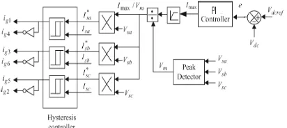
Fig.2.2.1 shows the blockdiagram of the implemented fuzzy logic control scheme of a shunt active power filter. Fig.2.2.2 shows the schematic diagram of the control algorithm. In order to implement the control algorithm of a shunt active power filter in closed loop, thee DC side capacitor voltage is sensed and then compared with a reference value. The obtained error e (=V
dc,ref-Vdc,act) and
the change of error signal ce(n)=e(n)-e(n-1) at the nth sampling instant as inputs for the fuzzy processing. The output of the fuzzy controller after a limit is considered as the amplitude of the reference current I
max takes care of the active
[image:5.612.46.252.463.555.2]© 2016, IRJET | Impact Factor value: 4.45 | ISO 9001:2008 Certified Journal
| Page 948
Figure2.2.1.Schematic diagram of closed loop fuzzy logic controlled shunt active power filter
The switching signals for the PWM converter are obtained by comparing the actual source currents (i
sa, isb, and isc) with the
reference current templates (i
sa *
, i
sb *
, and i
sc *
) in the hysteresis
current controller. Switching signals so obtained, after proper amplification and isolation, are given to switching devices of the PWM converter [6].
Figure2.2.2.Fuzzy Control scheme
3. Simulation Result
-
A program is developed tosimulate the both PI controller based and fuzzy logic based shunt active power filter in MATLAB. The complete active power filter system is composed mainly of three-phase source,
a nonlinear load, a voltage source PWM converter, and a fuzzy controller or a PI controller. All these components are modeled separately, integrated and then solved to simulate the system.
Figures 3.1-3.3 show the simulations results of the proposed shunt active power filter controlled by fuzzy logic and a conventional PI controller with MATLAB program. The parameters selected for simulation studies are given in table 3.1. The three phase source voltages are assumed to be balanced and sinusoidal. The source voltage waveform of the reference phase only (phase-a, in this case) is shown in fig.3.1. A load with highly nonlinear characteristics is considered for the load compensation. The THD in the load current is 22.05%. The phase-a load current is shown in figure 3.2. The source current is equal to the load current when the compensator is not connected.
System Parameters Values
Source voltage (Vs) 100V (peak)
System frequency (f) 50 Hz Source impedance
(Rs,Ls)
0.015ohm;0.12mH
Filter Impedance (Rc,Lc) 0.32ohm;2.8mH
Load impedance (Rl,Ll) 5.3ohm;17.5mH
DC Link capacitance 2000uF
Reference DC link voltage (Vdcref)
220V
© 2016, IRJET | Impact Factor value: 4.45 | ISO 9001:2008 Certified Journal
| Page 949
Fig.3.1 Result-1
Fig.3.2 Result-2
Fig.3.3 Result-3
From the responses it is depicted that the settling time required by the PI controller is approximately 10 cycles whereas in case of fuzzy controller is about 7.5 cycles. The peak overshoot voltage incase of PI controller is 880Volts (approx) whereas in case of fuzzy controller is 780volts (approx). The source current THD is reduced form 22.05% to 2.58% which is below IEEE standard with both the controllers. After compensation both source voltage and current are in phase with each other means that the harmonics are eliminated and reactive power is compensated to make power factor close to unity. As the source current is becoming sinusoidal after compensation power quality is improved.
© 2016, IRJET | Impact Factor value: 4.45 | ISO 9001:2008 Certified Journal
| Page 950
References-
[1]. W. M. Grady, M. J. Samotyj, and A. H. Noyola, “Survey of active power line conditioning methodologies,” IEEE Transactions on Power Delivery, vol. 5, no. 3, Jul. 1990, pp. 1536–1542.
[2]. H. Akagi, Y. Kanazawa, and A. Nabae, “Instantaneous reactive power compensators comprising switching devices without energy storage components,” IEEE Transactions on Industry Applications, vol. IA-20, no. 3, May/Jun. 1984, pp. 625–630.
[3]. S. Jain, P. Agarwal, and H. O. Gupta, “Design simulation and experimental investigations on a shunt active power filter for harmonics and reactive power compensation,” Electrical Power Components and Systems, vol. 32, no. 7, Jul. 2003, pp. 671–692. [4]. F. Z. Peng, H. Akagi, and A. Nabae, “Study of active power
filters using quad series voltage source PWM converters for harmonic compensation,” IEEE Transactions on Power Electronics, vol. 5, no. 1, Jan. 1990, pp. 9–15.
[5]. H.Akagi, “Trends in active power line conditioners,” IEEE Transactions on power Electronics, vol 9, no 3, 1994, pp 263-268.
[6]. S. K. Jain, P. Agrawal, and H. O. Gupta, “Fuzzy logic controlled shunt active power filter for power quality improvement,” Proceedings of Institute of Electrical Engineers, Electrical Power Applications, vol. 149, no. 5, 2002.
[7]. L.A.Morgan, J.W.Dixon & R.R.Wallace, “A three phase active power filter operating with fixed switching frequency for reactive power and current harmonics compensation,” IEEE Transactions on Industrial Electronics, vol.42, no.4, August 1995, pp 402-408. [8]. B. Singh, A. Chandra, and K. Al-Haddad, “Computer-aided
modeling and simulation of active power filters,”
Electrical Machines and Power Systems, vol. 27, 1999, pp. 1227–1241.
[9]. B. Singh, A. Chandra, and K. Al-Haddad, “A review of active filters for power quality improvement,” IEEE Transactions on Industrial Electronics, vol.46, no 5, Oct 1999, pp1-12.
[10]. R. M. Duke and S. D. Round, “The steady state performance of a controlled current active filter,” IEEE Transactions on Power Electronics, vol. 8, Apr. 1993, pp. 140–146.
[11]. J.W.Dixon, J.J.Garcia & L.Morgan, “Control system for three phase active power filter which simultaneously compensates power factor and unbalanced loads,” IEEE Transactions on Industrial Electronics, vol.42, no.6, 1995, pp636-641.
[12]. E.H.Watanbe, R.M.Stephan & M.Aredes, “New concepts of instantaneous active and reactive powers in electrical systems with generic loads,” IEEE Transactions on Power Delivery, vol.8, no.2, April 1993, pp.697-703.
[13]. K. Chatterjee, B. G. Fernandes, and G. K. Dubey, “An instantaneous reactive volt-ampere compensator and harmonic suppressor system,” IEEE Transactions on Power Electronics, vol. 14, no. 2, Mar. 1999, pp. 381–392.
[14]. Shyh-Jier Huang and Jinn-Chang Wu, "A control algorithm for three-phase three-wired active power filters under nonideal mains voltages," IEEE Transactions on Power Electronics, Vol. 14, No. 4, July 1999, pp 753-760.
[15]. D.A.Torey& A.M..Al-Zamel, “A single phase active filter for multiple nonlinear load,” IEEE Transactions on Power Electronics, vol.10, May 1995, pp.263-272. [16]. B. Singh, A. Chandra, and K. Al-Haddad, “Performance
© 2016, IRJET | Impact Factor value: 4.45 | ISO 9001:2008 Certified Journal
| Page 951
applied to an active filter,” 8th International conference on Harmonics and Power Qulaity ICHQP, Oct 1998, pp.133-138.
[17]. V.Soares, P.Verdelho & G.D. Marques, “An instantaneous active and reactive current component method of active filter,” IEEE Transactions on Power Electronics, vol.15, no.4, July 2000, pp.660-669. [18]. LEE C.C., “Fuzzy logic in control systems: fuzzy logic
controller part I and II,” IEEE Trans. Syst. Man Cybern, 1990, vol.20, pp.404-435.
[19]. V. S. C. Raviraj and P. C. Sen, “Comparative study of proportional-integral, sliding mode, and fuzzy logic controllers for power converters,” IEEE Transactions on Industrial Applications, vol. 33, no. 2, Mar./Apr. 1997, pp. 518–524.
[20]. Mohan, N., Undeland,.T.M, and Robbins,.W.P, “Power electronics :converters, applications and design,” Singapore,John Wiley and sons, 2003.
[21]. B. K. Bose, “Modern Power Electronics and AC Drives,” Singapore, Pearson Education,2004.