14th International Conference on Wireless Communications, Networking and Mobile Computing (WiCOM 2018) ISBN: 978-1-60595-578-0
Research on
General Radar Data Acquisition and Transmission System
Based on Windows CE
Xu-Dong Huang, He Huang, Qing-Liang Cheng, Z. Liu, Liang-Jian Jiang, Fu-Hong Gong,
Xu Zhang and Xin-Yang Ji
ABSTRACT
In order to solve the problem of single interface of radar data and cumbersome and error prone operation of radar data storage, a portable general radar data acquisition and transmission system is developed. The data delivery and transmission system takes WINCE as an embedded system platform, and uses C# platform for software development. It realizes real-time storage of radar data and radar data transmission function. The precision of radar time standard can be guaranteed by using FPGA technology to use precise BD/GPS to time system time, which can not receive BD/GPS data normally. The system has the characteristics of portable, universal and strong human-computer interaction.
Keywords—Embedded system; UDP protocol; data storage; network transmission
I. INTRODUCTION
The existing radar interface data can be reported to a single interface, which is not conducive to the interconnection and intercommunication of information. The operation procedure of data admission is tedious, easy to be misoperated and the human-computer interaction is poor. In some cases, the satellite timing information data can't be received normally, leading to the fact that the recorded radar data do not have the correct time scale information, so the general radar data acquisition and transmission system needs to be redesigned.
With the continuous development of mobile, intelligent, and network information technology, embedded technology has been widely used in all aspects of people's work and life. The commonly used embedded systems are LINUX, WINCE, etc. the WINCE system is an operation system developed by Microsoft Corp for mobile device terminals and embedded devices. Unlike other Microsoft Windows operating systems, Windows CE does not represent a software that applies the same standard to all platforms. In order to be flexible enough to meet the needs of a wide range of products, Windows CE can adopt a different standard pattern, which means that it can make a choice from a series of software patterns to make the product customizable. In addition, some of the available patterns can also be used as part of it, which means that these patterns can be a standard pattern by making choices from a set of available components. By selecting, Windows CE can achieve the minimum mode required by the system, thereby reducing the operation of storage scripts and operating systems. The system can integrate the complete mobile technology with the existing WINDOWS desktop technology. It is Microsoft's desktop operating system and programming using the same function, the interface style of the same most applications by modifying the transplantation can be used in the system, familiar with WINDOWS desktop application developers can directly carry out the WINCE application development, convenient and quick.
Therefore, this paper studies and implements a radar data acquisition and transmission system based on WINCE as the embedded system platform.
II. PRINCIPLEANDHARDWAREDESIGN
Figure 1 shows the schematic diagram of the system structure connection, and the system adopts the TINY 210 core board and extension board based on the CortexTM-A8 core. The core board uses Samsung S5PV210 as the main processor, the main frequency reaches 1GHz, the development board RAM capacity 1G, the ROM capacity of 4G, can meet the development demand. The CortexTM-A8 core processor supports many kinds of embedded systems, such as Wince, Linux, and so on. The processor uses a processor of 32 bit ARM simplification instruction set, which can reach the speed of 1GHz operation, the video coding and decoding capability is 1080p, the TV output (NTSC/PAL/HDMI) is supported, and the resolution code of LCD supports 1024 x 768. The application of this processor from smart phone to navigation device has perfect solutions. And integrated a lot of required components, such as wireless communications, personal navigation, video, mobile games, mobile music and video playback, mobile TV and PDA functions.It has a wide range of applications. TINY210 uses the time and positioning signs in the $GNRMC information output from the UM220-III N module to generate the date and time information required by the radar. At the same time, the time information of another $GNRMC information output by UM220-III N module is used to set up the initial time of the _________________
system, so that when the BD/GPS module fails to receive normally, it can read the exact system time and generate the time information needed by the radar. The radar data that obtains the correct time information is stored in the data. The stored data can be stored in U disk or SD card, and the radar data can also be output through the network interface on the extended board. Seven Inch Touch liquid crystal display screen can carry on human-computer interaction, control each module, display the parameter and so on.
Embedded
system
(man-machine interface)
232-TTL
7 "touch LCD screen
BD/GPS module
Network transmission
RAM
RADAR
data storage
( NANDFLAS(
USB SD card FPGA
( Data time)
(System timing)
Figure 1. A/R display on the target reflection signal separation process.
III. FUNCTIONDESIGN
The system is divided into four parts, namely, radar data acquisition and processing, radar data storage, system timing, and UDP network data transmission. The TINY 210 development board adopts CortexTM-A8 as controller, receiving radar data and navigation satellite timing data, and displays the working status and parameters of the system through the 7 Inch Touch screen. For the radar data that obtains the correct time information, the data is stored through the NANDFLAS in the extended board. The receiving satellite navigation time data and the 1PPS synchronization information are processed by FPGA, and the initial time of the system is given time.
In this article ,we use 1PPS BD/GPS for fellow reasons.1PPS, the BD/GPS second pulse signal PPS one second, its function is used to indicate the time of the entire second, and the time is usually marked with the rising edge of the PPS second pulse. BD/GPS can give UTC time, when the user receives the time delay, in order to accurately give time, the PPS signal rising edge is introduced to mark the entire second time of the UTC, the precision can be high to the nanosecond level, and there is no cumulative error.
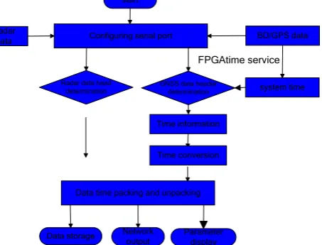
The data is received by the navigation satellite, and the IP address is set through the touch screen. The radar data is transmitted by the UDP network protocol. The overall functional block diagram of the system is shown inFigure2.
start
Configuring serial port
Radar data head
determination GNSS data header determination
BD/GPS data Radar
data
Data time packing and unpacking
Data storage Network
output Parameter display
system time FPGAtime service
Time information
[image:2.595.169.421.141.319.2]Time conversion
[image:2.595.192.419.540.712.2]IV. SOFTWAREDESIGN
The software of radar data acquisition and transmission system is developed by the C# language on the VS2005 platform, and the special SDK (software development kit) of the TINY210 development board is used. The software running interface of the system is shown in Figure 3. The left part of the software interface is mainly set up for the radar serial port, the port of the GPS serial port and the baud rate. Display BD/GPS timing information, positioning state receiving, serial data reception and display of radar data frames; the middle part is to display the target time, batch number, distance, azimuth and height parameters; the right part selection function, can realize the serial port control, GPS/ radar system timing, data storage, network output and other functions choose. The following four functional subsystems are introduced, including radar data acquisition and processing, radar data storage, system timing and UDP network data.
Figure 3. System software running interface.
A. Radar Data Acquisition And Processing
The main function of this module is to use the time and location markers in the $GNRMC information output from the um220-III N module to generate the date and time information required by the radar. Radar SerialPort data and UM220 SerialPort time information receive the SerialPort control. The software flow is shown in figure 4. The UM220 - III N module is based on a dual system multi frequency high performance low power GNSSSOC chip. This chip can simultaneously support up to 6 different frequencies of satellite signals, covering 12 frequency points of 4 large navigation systems such as BD/GPS and so on. It can resist dozens of monosyllabic interference and support millimeter measurement precision. The front chip uses RFIC, which integrates low noise (LNA), mixer (MIXER), intermediate frequency amplification and filter, digital to analog converter (ADC), automatic gain control and local oscillator frequency synthesizer. The integrated two chip realizes the accurate reception of BD Positioning Data by external antenna. UM220 - III N serial port (UART) 1 is the main serial port, supports data transmission, connects the TXD of the serial port with the RXD of the serial port 1 of the development board, and sends the received location data to the development board, the default baud rate is 9600B/S. Connect the TXD of the serial port 2 to the RXD of the FPGA, so that the received location data can be transmitted to the development board, and the default baud rate is 19200B/S.It is highly integrated and easy to apply, and is very suitable for small size BD module.
start
Configuring serial port
Radar data head
determination GNSS data header determination Radar data processing,
UDP output, data storage
and display Time processing
BD/GPS data Radar data
Software initialization
Data time packing
B. Time
GNSS time processing is mainly to analyze the data output frequency of um220-III for 1Hz of $GNRMC information, and read the date of the year, and the time interval information is obtained in UTC time. The obtained UTC time is converted to Beijing time as radar data. The flow diagram is shown in figure 4. The data format of GNRMC is as follows:
$--RMC,time,status,Lat,N,Lon,E,spd,cog,date,mv,mvE,mode*cs
First open the serial interrupt service subroutine, begin to receive data, judge whether it has “*GNRMC” symbols, and then judge the type of data according to the number of comma, and then store time, longitude, latitude, date and other signals respectively, if received“*”then the end.
Because the time of BD/GPS module output is UTC world time, Beijing time is commonly used in our country, its time difference is 8 hours, that is, Beijing time is 8 hours faster than U TC time, so it should be added 8 hours at the time received by GPS, if more than 24 hours, then second days, and the date plus 1, and Time minus 24 hours is the right time for Beijing.
Waiting for GNSS the receive
interrupts
Receiving a frame of data
Analysis of RMC information ,extraction
time
Converting UTC time to Beijing time
YES
[image:4.595.166.425.229.342.2]NO
Figure 5. Time processing software flow chart.
C. System Time Modification
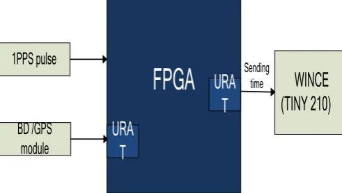
The module USES UM220 - III N output module of the satellite navigation GPS clock data and 1 PPS synchronization information by the FPGA, the initial time of the system set, can make the BD/GPS module can't normal receive, can read the time needed for accurate system time to generate radar information. The system timing flow chart is shown in figure 6.
In this article uses the following methods to modify wince system time by c# programming. 1. need to call the dynamic library coredll.dll
2.files need to be added using System. InteropServices; using System.IO; using Microsoft.Win32;
3. when defining a structure, 8 parameters must be included, such as fewer errors.
Because calling SetLocalTime is invoked in the form of pointer. If there are fewer parameters in the structure, SetLocalTime will make mistakes when looking for addresses.
FPGA
BD /GPS
module
URA
T
URA
T
WINCE
(TINY 210)
1PPS pulse
Sendingtime
Figure 6. The flow chart of System time modification.
D. Data Storage And Network Output
[image:4.595.174.420.523.662.2]programming interface. Software programming uses the StreamWriter class of file read-write operations, and the WriteLine method below this class writes the string to the text stream in an automatic appending line. The StreamWriter class allows characters and strings to be written to the file, instead of being converted to bytes. It processes the underlying transformation and writes data to the FileStream object.
Radar data network output is made based on the connectionless Udp protocol. The full name of the UDP protocol is user datagram protocol. It is used in the network as a TCP protocol to handle data packets. It is a connectionless protocol. In the OSI model, the fourth layer, the transport layer, is on the upper level of the IP protocol. UDP protocol has its unique advantages in our interconnection design: first, the UDP protocol has high transmission efficiency without the need of connection overhead before TCP communication; second, the UDP protocol is simple and requires no complex state machine transmission mechanism, so the execution time is greatly reduced and the speed is guaranteed. Third, UDP protocol can also be broadcast. In this way, UDP protocol is widely used in the application and development of the network. For example, our common chat software, ICQ and OICQ, are used to communicate with the UDP protocol. The reason why we choose UDP is mainly based on the agreement can eliminate delays and generate connection system support one-to-many connection, more suitable for actual demand of equipment.
There are two ways to program C# in UDP: direct use of Socket class and use UdpClient class. The UdpClient class encapsulates the base Socket and does not have to consider some details that the underlying socket must handle when sending and receiving the data, which is simple and efficient.
In this article , We use UdpClient in c# to achieve unicast function and multicast function. The UdpClient class provided by C# for unicast function is simple and easy to use, and is no longer detailed here. Here, we focus on multicast.
Multicast is to send messages from a computer to the selected computer subset of the network or the whole network, which is sent to those computers that join the specified multicast group. The multicast group is open, and each computer can be added to the multicast group at any time by the program, or leave at any time. A multicast group is a set of devices that share a multicast address. Similar to IP broadcasting, IP multicast uses special IP address ranges to represent different multicast groups. Multicast addresses are D class IP addresses ranging from 224.0.0.0 to 239.255.255.255. Any messages sent to multicast addresses will be sent to all members of the group. The group can be permanent or temporary. Most multicast groups are temporary and exist only when there are members. When a user creates a new multicast group, just select an address from the address range, and then construct an object for the address, you can start sending the message. When using multicast, we should pay attention to the setting of TTL (Time To Live). The TTL value is the maximum number that allows the router to forward, and when the maximum value is reached, the packet will be discarded. If the default value is used (the default value is 1), it can only be sent in the subnet. You can directly set TTL values and implementations through the TTL property of UdpClient objects.
V. THESYSTEMTEST
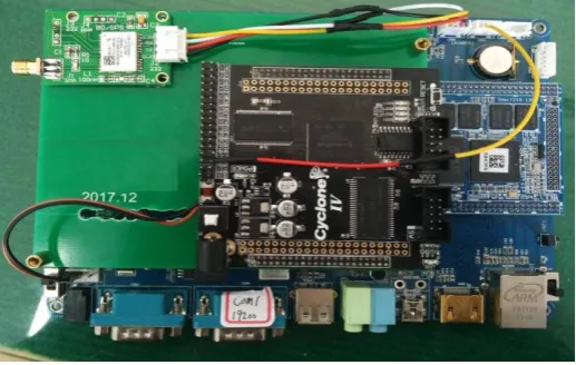
[image:5.595.169.428.511.675.2]The system test is mainly to simulate data debugging and computer test. The test shows that the system is stable and reliable, and the problems existing in the original data admission system are solved better. Figure 7 shows the system hardware circuit.
Figure 7. System hardware circuit.
VI. CONCLUSION
time with precise BD/GPS, which can guarantee the accuracy of radar in the environment where BD/GPS data cannot be properly received. The system has the characteristics of portability, universal and human-computer interaction, and has a wide application prospect.
REFERENCES
[1] Huai Yang, Shao Qiongling, Lu Zhen Min. Beidou /GPS hybrid positioning module UM220 application research. Foreign electronic measurement
technology, 2014, 33 (3): 76-79.
[2] Zhang Song, Li Yun.FPGA modular design method [J]. Journal of electronic measurement and instrumentation, 2014, 28 (5): 560-565.
[3] Wang Peng, Cheng Yun, Dong Shuli. Design of multi format data transmission based on FPGA. Electronic measurement technology, 2014, 37 (1)
70-75.
[4] Li Lanying, Nios II embedded soft core SOPC design principle and application [M]. Beihang University press. 2006:1-53.
[5] Lu Yuhong, C# from entry to master [M] (Second Edition). People's Posts and Telecommunications Press. 2015.
[6] Yang F J, Principle of radar countermeasure, University of Electronic Science and Technology Press,pp.134-135, 1997.
[7] Xiang J C,Zhang M Y, Radar system,University of Electronic Science and Technology Press, pp 88-90, 1998.