2018 3rd International Conference on Computational Modeling, Simulation and Applied Mathematics (CMSAM 2018) ISBN: 978-1-60595-035-8
A Control System Based on Microprocessor and FPGA for 1470nm
High-power Semiconductor Laser
Ning-ning DONG, Jin-jiang CUI
*and Jian-gen XU
Suzhou Institute of Biomedical Engineering and Technology Chinese Academy of Sciences, Suzhou 215163, China
*Corresponding author
Keywords: Control system, 1470nm, Laser.
Abstract. An intelligent control system for a medical high-power semiconductor laser has been developed. The system combines 1470nm high-power semiconductor laser and intelligent control technology. The control technique applies an ARM Cortex-M3 microprocessor STM32F103 as the core, an FPGA to drive the digital constant current source module and the power feedback loop to realize constant power control. Furthermore, the display and storage of the output data, and the driver of the touch screen are realized by designing the main control module and human-computer interaction module with the microprocessor. Finally, the Micro-Controller Development Kit (MDK) platform is used for programming. The safety performance of the whole control system conforms to the national standard of medical electrical safety.
Introduction
At present, the semiconductor laser has been widely used in industrial, commercial, scientific research, information, military and medical aspects due to its advantages such as light weight, small size, high efficiency, stable output power, easy to optical fiber transmission and so on [1-8]. Laser medical equipment has been widely adopted in various fields of disease treatment, such as ophthalmology, surgery, cardiology, dermatology, etc. New 1470nm semiconductor laser with high water absorption coefficient, strong cutting ability, certain solidification, hemostatic effect, high fat absorption, can be effectively applied in the treatment of common diseases such as minimally invasive surgery, skin beauty and vascular lesions and high lipolysis. STM32F103 series microprocessors with the architecture of ARM Cortex-M3 have high performance, low cost and rich external interface, with built-in nested vector interrupt controllers are built to meet the real-time security control requirements of medical devices. In order to meet the development needs of laser medical instruments and provide convenient intelligent control platform for instrument operators, this report designs a 1470nm high-power semiconductor laser medical treatment control system based on STM32F103.
The System Design
series microprocessor, interfaces isolating circuit and so on, which is mainly developed to complete the output of the relevant data display and storage, and to be responsible for the touch screen driver, signal response, light control, and other functions.
1470nm high power semiconductor
laser module laser driver
control module PID temperature control module
master control module
touch screen treatment handle optical fiber system
[image:2.595.210.385.118.250.2]power supply
Figure 1. Principle diagram of laser control system.
Hardware and Software Design
Laser Module
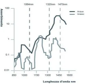
The core light of the laser therapeutic apparatus is 1470nm semiconductor laser, as shown in figure 2. The apparatus has high water absorption coefficient, strong cutting ability, certain solidification, hemostatic effect and high lipolysis. The characteristics of 1470nm high power semiconductor laser are as follows: It has single fiber output; the output power is greater than the 17W; center wavelength of 1470nm±20nm; optical fiber is 400 microns in diameter; fiber numerical aperture is 0.22; FWHM is less than 15nm; working voltage is less than 3V; working current is less than 60A; working
temperature is 20 ℃. Figure 3 shows the characteristic curve of the semiconductor laser module.
Curve A in purple is the volt-ampere characteristic curve, and curve B in blue is the relation curve between driving current and power.
[image:2.595.188.482.466.620.2]
Figure 2. Absorption rate of water and fat. Figure 3. Characteristic curve of laser.
Laser Drive Control and PID Temperature Control Module
The driving control and temperature control indicators are as follows:
1) voltage: 0-2v adaptive; 2) current: 0~50A continuously adjustable; 3) peak value of current ripple: <0.1%; 4) pulse width modulation range: 100μs-10s; 5) power control stability: <1.0%; 6) TEC drive capacity: 0~12V, 0~17A; 7) TEC parameters: the maximum voltage is 17.5V, and the
maximum current is 15A. Two in parallel; 8) temperature setting range: 15 ~ 35℃ with the accuracy
of 1℃.
[image:2.595.109.256.472.617.2]1470nm semiconductor laser. The main control module uses RS232 protocol to transfer laser working parameters, operation mode, the information such as alarm signal. Among them, MCU is responsible for protocol analysis of RS232, and FPGA is responsible for digital control signal of constant current source, driving signal of TEC, digital PID calculation and other functions. Main control circuit chip with floating structure in constant current source is developed to provide adequate protection for laser, at to synchronously provide the output short circuit, open circuit detection, overload protection, electrostatic protection and some other protection functions.
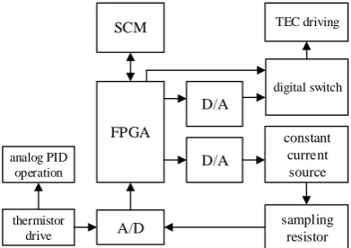
The laser drive control module adopts pulse width modulation (PWM) technology to reduce the power consumption. The laser temperature control circuit adopts the technology of simulating PID control and digital PID control to realize reliable and accurate temperature control.
[image:3.595.200.396.218.356.2]constant current source SCM FPGA A/D D/A D/A sampling resistor thermistor drive TEC driving digital switch analog PID operation
Figure 4. Basic structure diagram of laser drive control module.
Main Control Module
Design of the main control hardware circuit mainly consist of microprocessor, main control module power circuit, interface isolation circuit, temperature monitoring circuit, power feedback circuit and serial communication circuit.
Main control module mainly completes the requirements of user and treatment, which control output requirements of laser module and make it high and stable work within the overall technical specifications of the equipment. At the same time, the main control module completes the output display and storage of relevant data, and drives the touch screen, and completes the touch screen signal response, indicator light control and other functions. In security section, the main control module is responsible for the real-time monitoring of the laser temperature and output power value, the fault alarm in time, driving the laser red light that indicate the safe operating laser. Schematic diagram of main control module structure is shown as figure 5.
AD DA G P I O USART Interface isolating signal conditioning signal amplification voltage conversion laser driver thermistor drive temperature sensor Temperatur e sensing drive PD drive laser power detection MCU touch screen
Figure 5. Schematic diagram of main control module structure.
The microprocessor
[image:3.595.184.413.568.702.2]two DMA channels, the chip operation efficiency can be improved, and built-in nested vector interrupt controllers are built to meet the real-time security control requirements of medical devices.
Power circuit of main control module
System power input voltage of main control module is 24VDC, the voltage of simulation and interface section is 5V, the microprocessor section voltage is 3.3V, so it generates 5V and 3.3V voltages by the linear voltage-stabilizing circuit and the voltage reversal circuit. LM2576 series voltage-stabilizing circuit chip and LM1117 series low-voltage differential voltage regulator is selected for voltage conversion design.
Interface isolating circuit
Voltage conversion is required at the threshold output, peak output, red light indicating output, foot pedal switch, remote control linkage and both ends of single-chip transmission circuit. Analog part and external trigger are 5V, the micro-controller working voltage is 3.3V, TLP521-1 is used to design the isolation switch voltage circuit for signal transmission on the signal output terminal and signal at the receiving end parts for the circuit interference into consideration. TLP521-1 is a controllable photoelectric coupler, that can increase security, reduce circuit interference and simplifies circuit design by isolating completely the front from the load.
The Software Design
The main control module is STM32 series chips based on ARM core, and the common development tool is the ARM development tool MDK developed by Keil. The system realizes logic control through C programming on the basis of IC of STM32. There are mainly timing counter, external interrupt, internal interrupt, communication interface and so on. IC receives touch screen instructions by a serial port communication protocol, and sends instructions to the relevant power supply after interruption parsing, which changes the power supply data by a serial port protocol, and controls power supply work by external IO. In addition, the work of the whole machine, emergency stop, temperature monitoring, optical fiber monitoring and so on are realized through external interruption to achieve the maximum real time. General output, such as LED, buzzer, etc., is controlled by IO, and the laser output uses the timer for accurate timing output.
The main program starts from the main function. First, the system is initialized, including driver initialization, switch initialization, timer initialization and serial port initialization; then the parameters are initialized, including the pulse width, frequency and standby interface; then the hardware self-check is turned on to detect pedal switch sign, remote control linkage state and fiber inspection; it needs to open the laser temperature monitoring, and open temperature control, which can adjust the temperature, it can receive data when the temperature adjustment to the set temperature and the feedback to switch to the standby screen interface; then it receives screen data, and chooses the work mode first, it will get ready after setting, and the microprocessor will receive and process data; next, the laser opens by stepping on the foot switch at this time to open and interrupt; last, the laser closes by loosen the foot pedal switch. This is a complete working process.
Measurement Experiments and Results
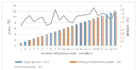
Stability Test of Laser Output Power
Figure 6. Test chart of deviation between target power and average of measured power.
Whole Machine Safety Performance Test
The medical leakage current tester of Nanjing changsheng CS550 series is used to test the leakage current of the whole machine's shell, the test results are as follows: normal state: 0.002mA, single failure: 0.002mA; the test results of ground leakage current are as follows: normal state: 0.185mA, single fault: 0.396mA. The withstand voltage capacity of the whole machine is tested by CS50 series pressure tester, the test result is as follows: the pressure resistance between the live part and the unsecured earthed housing component reaches 4000V. The protection ground impedance of the whole machine is tested by CS5800/Y series ground resistance tester, the test result is as follows: protection of grounding resistance is 0.02 Ω. The test results comply with GB 9706.1-2007 medical electrical equipment part 1: safety general standard for shock hazard protection requirements, it ensures the safety of the application personnel.
Conclusion
An intelligent control system for a medical high-power semiconductor laser has been developed. The system combines 1470nm high-power semiconductor laser and intelligent control technology. The device consists of an ARM Cortex-M3 processor STM32F103 as the core, an FPGA-driver the digital constant current source module, and the power feedback loop realizing constant power control. The output pulse width is continuously adjustable in the range of 20ms-1000ms with 10ms step. The output power is continuously adjustable in the range of 0-12w with 0.5W step. Its working modes include single-pulse, multiple-pulse and continuous output. In order to treat different diseases, the aforementioned parameters can be intelligently set. The system is easy to operate with the true color touch screen to realize human - machine interaction. The control interface is designed by SGUS, which is a special graphical application service. This intelligent control system can maintain stable and reliable work with high safety strong anti-interference ability, and lower cost than similar imported products. Therefore, the laser treatment system is expected to have wide market and application prospects in China.
Acknowledgement
This research was supported by the National Key R&D Program of China (No. 2017YFB0403802), Technology Cooperation High-tech Industrialization Program of Jilin Province of China and the Chinese Academy of Sciences (No. 2018SYHZ0023), Key Technology R&D Program of Jilin Province of China (No. 20180201047YY).
References
[1] Banin A Z, Moraes L M, Gondek L, et al. Laser lipolysis: flaccidity under control [J]. Aesthetic Plast Surg, 2002, 26(5):335-339.
[3] Debobrato D, Stephanie R, Perry R. Klokkevold, Benjamin M. Wu. A high-throughput comparative characterization of laser-induced soft tissue damage using 3D digital microscopy[J]. Lasers in Medical Science, 2013, 28(2):657-668.
[4] Xiao-fu Qiu, Hua-ru Zhang, Guo-sheng Yang. Advances in the treatment of benign prostatic hyperplasia by 1470nm semiconductor laser[J]. Journal of Contemporary Urologic and Reproductive Oncology, 2017, 9(3): 190-192. (in Chinese)
[5] Jing Qian. The application of semiconductor laser in patients with recurrent oral ulcer[J]. Medical Equipment, 2017, 30(20): 104. (in Chinese)
[6] Xiao-hong Zhang, Gan Shen. Clinical Observation of Steroid-Dependent Dermatitis Treated by Diode Laser[J]. Journal of Tissue Engineering and Reconstructive Surgery, 2017, 13(5): 294-295. (in Chinese)
[7] LI Q. Clinical study of a new type of body contouring method for 1470nm semiconductor laser[D]. Southern medical university, 2013. (in Chinese)