2019 International Conference on Computation and Information Science (ICCIS 2019) ISBN: 978-1-60595-644-2
Molecular Dynamics Simulation of Gas
Pipeline Steel Based on LAMMPS
Parallel Computing Platform
Haijun Qu, Ling Chen, Minan Wang, Xinhan Dai, Hongkun Chen,
Gongzhen He and Taolong Xu
ABSTRACT
Along with the advent of the fourth industrial revolution, the processing capacity of "big data" is highly demanded in industry community. Compared with the traditional computing and programming model based on serial program, parallel computing is based on heterogeneous architecture and runs in a completely different way from CPU, which has greatly enhanced the processing speed of large-scale data sets. Therefore, parallel computing has been developing dramatically in recent years, and has been favored by all walks of life. In the future, large-scale data processing must belong to parallel computing. Set on LAMMPS (large-scale atomic/molecular massively parallel simulator) as an example, this paper described the technique of establishing parallel computing platform, and applied it on simulated test on fracture process of lamellar structure from gas-pipeline steel.
1. INTRODUCTION
With the advent of the informationalized era, big data, cloud computing and other new concepts come one after another. In the digital environment, data to be processed is also beginning to be quantified in GB or TB. Under the condition that
the domain frequency of CPU is fixed, the computing efficiency of computer decreases obviously when the data sets need to be processed are increasing. Though using classical processing algorithms with excellent performance in various aspects, it is constrained by electronic components and serial algorithms which have reached the physical limit. Hence, the previous methods need longer time to complete the processing of large-scale data. Parallel computing saves a lot of time and space costs by decomposing a computing task into several sub-tasks, then distributing sub-tasks into different processing units. Collaborations among different processing units can solve them quickly. It is predictable that parallel computing will be popular, and will substantially reduce the processing time of data sets.
2. THE PROCESS OF BUILDING A PARALLEL PLATFORM
Get ready to install
the packages compilers are installed on the machineCheck whether the C and FORTRAN Install fftw Install mpich
Install jpeg Install voro++
Install lammps Calculate example
in parallel Successful
installation
[image:3.612.105.492.88.229.2]Reinstall
Figure 1.1. LAMMPS parallel compilation and build process.
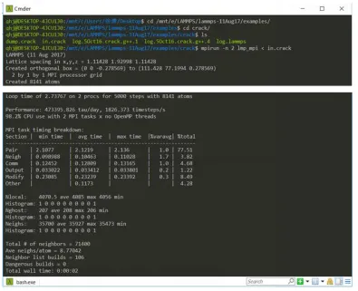
The compilation of the meam and poems installation packages in LAMMPS needs to be performed after lammps, fftw, and mpich have been installed. The parallel compilation process for the meam and poems installation packages is shown in Figure 1.2 below. After the LAMMPS parallel platform is initially set up, enter the lammps decompression package and enter the crack folder under the example folder to execute the command $ mpirun -n 2 lmp_mpi < in.crack. If it can be calculated, it means that the platform is built successfully, and some calculation process is shown in Figure 1.3.
Compile the required
installation packages the library file and compile itModify makefile.lammps in Makefile.g++ Compile Make yes-meam
Make yes-poems
cd ~ /lmp/src/MAKE Gedit Makefile.g++
[image:3.612.106.493.482.518.2]Figure 1.2. Successfully calculating example in parallel.
3. APPLICATION EXAMPLE
3.1 Modeling
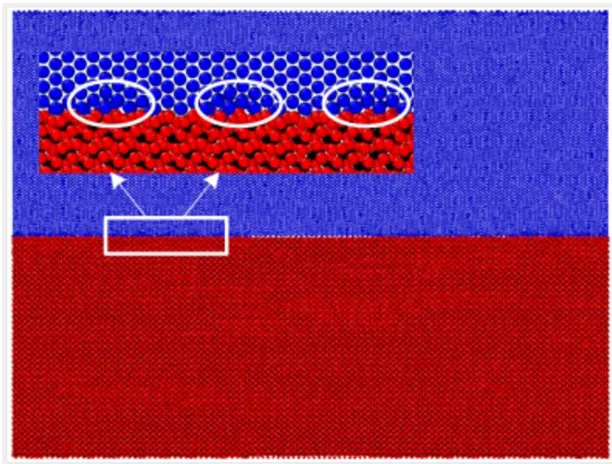
A three-dimensional atomic model with a penetrating crack is established in ATOMSK. As shown in the red part of Figure 2.2, the part of cementite model contains 40, 4 and 28 unit cells respectively in three directions. The size of the model is 20.24 nm×2.731 nm×12.628 nm and it contains 71680 atoms. As shown in the blue part of Figure 2.2 the part of ferrite model whose size is 20.269 nm× 2.696 nm×12.638 nm contains 50, 11 and 18 unit cells respectively in three directions and contains 59400 atoms.
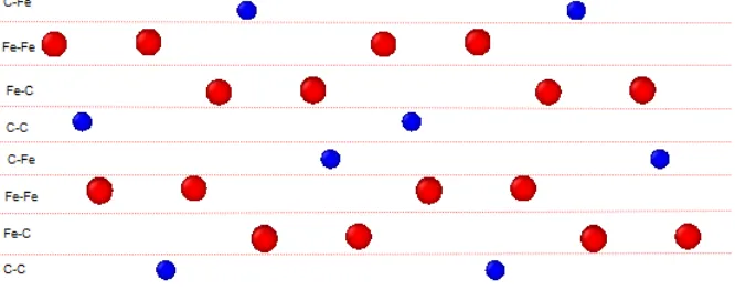
freed at the interface. The first consideration is the terminal type of the crystal at the interface. For ferrite, on account of its highly symmetrical crystal structure, the structure and chemical properties of its termination plane are the same which means there is no need to consider the terminal type of ferrite. Nevertheless, owing to complex oblique crystal structure of cementite, the terminal type needs to be considered. Figure 2. shows eight different cementite termination planes.
Figure 2.1. Terminal plane of cementite.
3.2 Atomic Simulation Process
3.2.1 SELECTION OF POTENTIAL FUNCTION
The molecular dynamics calculation results are closely related to the selected potential function. In this paper, four typical iron-carbon system potential functions are selected for comparison, including Lennard-Jones/Morse potential function, EAM potential function, Tersoff potential function and MEAM potential function. Considering both accuracy and cost, Tersoff potential function is consequently used in the subsequent simulation process.
3.2.2 RELAXATION TO MINIMIZE ENERGY
minimize its energy, it is first tested for experimental conditions. Ma Wen et al [9]
,in the molecular dynamics simulation of nano-polycrystalline metal samples, did two-step relaxation to the simulation samples, the static optimization of energy and the NPT dynamics optimization under constant temperature and constant pressure, which effectively reduced the residual stress inside the samples and reached the test state. This can be used as a reference for the energy minimization method in this experiment.
[image:6.612.143.449.351.583.2]After using the conjugate gradient method to minimize this model’s energy, the NPT constant temperature and constant pressure relaxation of 30 ps with a temperature of 300 K and a pressure of 0 bar is performed. When the relaxation is completed, the model is introduced into OVITO and it is found that in addition to the pre-crack in the middle section, the upper and lower distances between the interfaces no longer exist, and even some ferrite and cementite atoms have merged, as shown in Figure 2.2.
Figure 2.2. C-Fe terminal relaxation model.
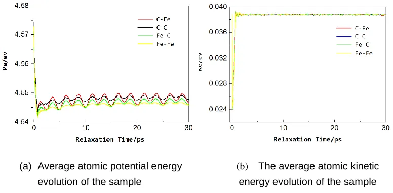
drops rapidly at the initial stage of relaxation, it gradually becomes stable after 5 ps, and the average atomic kinetic energy of the sample rapidly rises and stabilizes at an early stage. It can be seen from the figure that from the energy point of view, the energy reaches an equilibrium state after the CG energy minimization and the NPT constant temperature and constant pressure relaxation of 5 ps. Therefore, it is reasonable to use CG energy minimization and NPT constant temperature and constant pressure relaxation of 30 ps.
Figure 2.3. The evolution of sample size with relaxation time.
3.2.3 UNIAXIAL TENSION LOADING
Under the NVT ensemble, after the sample is fully relaxed, it is subjected to uniaxial strain tensile loading along the Z direction, and periodic boundary conditions are applied in the X direction and the Y direction to reduce the effect of the size effect. Under the experimental temperature of 300K, the strain rate is 5×10⁸ s-1 and the loading step is 1fs.In the simulation process, the atomic information is recorded every 0.2 ps. In order to refine the numerical value of this experiment, when at 0.2 ps the atomic stress and its displacement value are calculated, the average value of the data of 10 time steps near this time is taken as the output value.
(a) Average atomic potential energy
evolution of the sample
(b) The average atomic kinetic
3.3 Analysis of Results
[image:8.612.171.431.441.644.2]Under the condition of 300K, the stress-strain curves of cementite surfaces of the four different terminations under tensile loading are obtained, as shown in Figure 2.4. It can be concluded from the figure that in the uniaxial tensile test, each model undergoes an elastic process in which the stress increases linearly with the load strain. When the critical points are met, the cracks rapidly expand due to the chemical bond rupture between the atoms. The stress gradually drops into the passivation period, and the material failure rapidly occurs, and then the stress gradually decreases to zero. It can also be observed from the figure that the maximum stress values of the C-Fe terminations and the C-C terminations are larger than those of the Fe-Fe and Fe-C terminations, which may be because that the surface is more stable when the carbon atoms are located at the outermost layer of the cementite termination. In the meanwhile, we can see that when the outermost two layers of atoms at the surface termination of the cementite do not contain C atoms, that is, the Fe-Fe termination, not only its maximum principal stress is far smaller than any other termination model’s maximum principal stress, but also it is the one whose stress first decreases to zero and reaches failure state. And the stress is reduced to zero at the slowest speed when the outermost two layers of cementite are all C atoms.
4. CONCLUSIONS
Compared with the traditional sequential computing method, parallel computing has the advantages of high throughput, low time cost, and resource saving. The steel sheet structure model of α-Fe&Fe3C material was established by LAMMPS and the
calculation structure was visualized by OVITO software. Then, the fracture process of the steel sheet structure is simulated, and the microscopic fracture of the steel sheet structure is explored by molecular dynamics method. The molecular dynamics theory was applied to simulate and analyze the material by establishing LAMMPS simulation calculation on the atomic scale of the steel sheet structure. Hence, it can be seen that the LAMMPS molecular dynamics parallel computing platform is extremely applicable and efficient in materials science and computational chemistry.
REFERENCES
1. Shuai Shao, 2019. “The Development and Prospect of Parallel Computing,” Technology and
Economic Guide, 2019, 27(02):6.
2. Wenzhi Liu, 2015. “Parallel Algorithm Design and Performance Optimization,” Beijing
Machine PRESS, 2015.
3. Girifalco L A, Weizer V G.1959, “Application of the Morse Potential Function to Cubic Metals,”
Phys Rev, 1959, 114(3):687-690.
4. Duan H, Ding F, A. Rosén, et al. 2007, “Initial growth of single-walled carbon nanotubes on
supported iron clusters: a molecular dynamics study,” European Physical Journal D, 2007,
43(1-3):185-189.
5. Xia Z, 2004, “Curtin W A Pullout forces and friction in multiwall carbon nanotubes,” Physical
Review B, 2004, 69(23):233408.
6. Hepburn D J, Ackland G J, 2008, “Metallic-covalent interatomic potential for carbon in iron,” Physical Review B, Condense matter, 2008, 78(16):165115.
7. Henriksson, K. O E, Nordlund. 2009, “Simulations of cementite: An analytical potential for the
Fe-C system,” An introduction to Riemann-Finsler geometry/Springer, 2009.
8. Liyanage L,Houze J,Kim S,et al. 2014, “Structural, elastic and thermal properties of cementite
(Fe3C) calculated using Modified Embedded Atom Method,” Physical Review B, 2014,
89(9):106-112.
9. Ma Wen, Zhu Wen-Jun, YaLin Zhang, et al. 2010, “Construction of metallic nanocrystalline