2019 International Conference on Computer Science, Communications and Multimedia Engineering (CSCME 2019) ISBN: 978-1-60595-650-3
Application of Fuzzy PID Adaptive Algorithm Based on RBF
Network in Smart Car
Yan-yong JI and Fang DING
College of Electronic Information and Automation, CAAC University
Keywords: Smart car, Track recognition, Fuzzy control, RBF neural network.
Abstract. Smart car speed control system is a nonlinear time varying systems, to establish a precise mathematical model isn’t easy, using conventional PID control is not very good. This paper proposes to combine the RBF neural network with fuzzy control by analyzing the smart car system. The collective fuzzy control and neural network control can not only make good use of existing experience knowledge to solve the problem of black box characteristics, but also improve control precision and realize adaptive function in time. The experimental and simulation results show that the proposed direction and speed control algorithm can meet the requirements of the smart car running stably for a short time.
Introduction
Smart car focuses on intelligent control, sensor technology, communication technology and so on. It doesn't require human involvement, it's completely autonomous. The theoretical basis of the smart car system is the closed-loop control system. During the operation process, path planning and Behavior decision are made according to the set environmental parameters and real-time environmental information [1]. Smart car system is through the micro control unit to coordinate control circuit acquisition module, power module, motor drive module, steering module, encoder speed measurement module, etc. So that they work in a unified and coordinated way to achieve the predetermined function. Power electronics technology and sensor technology and the optimization of path identification method, intelligent control technology is becoming more and more perfect. The speed control algorithm and direction control algorithm of smart car have become the core content of whether smart car can achieve a qualitative leap, and it is also the problem that needs to be broken through in the research of smart car at present. This paper adopts the method of combining RBF neural network and fuzzy control to control the speed of smart car.
Smart Car Control System Structure
Smart car control system includes microprocessor, power module, motor drive module, track information acquisition module, steering module, sensor speed measurement module and liquid crystal display module.
The smart car collects track information in front of it through sensors, and transmits the track information to the main controller, which makes corresponding motion decisions based on track information and the current state of the vehicle body. Controlling the steering gear and DC drive motor action by changing PWM duty cycle to achieve steering and speed regulation of the vehicle body [5].
Smart Car Speed Control Algorithm Design
When the camera collects the track image information, the collected information is transmitted to the single-chip microcomputer through I/O, and the black line information on both sides of the track is extracted by running algorithm program, and the current driving state of the car body is combined to guide the car to drive forward, so as to achieve accurate and fast tracking.
according to the input position deviation, a deviation corresponds to a steering gear setting, and the angle setting of the steering gear is determined by the pulse width of the input control signal. This paper mainly studies the speed control method and strategy.
[image:2.595.92.489.172.228.2]The speed control system is a nonlinear time varying system. Different from the direction control system, Different speed values are set according to different tracks and adjusts the speed timely to reach the expected value by comparing with the real-time speed feedback from the speed sensor. Its control principle is shown in figure 1.
Figure 1. Smart car speed control system diagram.
Establishment of Mathematical Model of Smart Car
Assume that the horizontal velocity of the smart car is v and the acceleration is a, and the car body is subjected to the horizontal thrust F to the right and the horizontal friction f to the left. The horizontal dynamic expression of the smart car can be given by function(1):
ma F Kv (1) The car mass m can be directly measured to be about 1.2kg. The maximum speed vmax of the car
measured for several times is 2.4m/s, and the time of the car accelerating from stationary to vmax is
about 2s, so K=1.33 and F= 4.66N can be estimated. Then the mathematical model of the car can be given approximately by function(2):
6.2
0.9 1
p G s
s
(2)
PID Control Algorithm
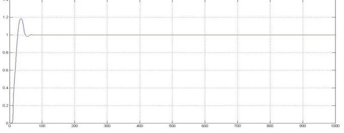
PID control algorithm is used to adjust the speed of smart car motor, and then to control the actual speed. After many experiments, Kp=0.6, Ki=1.2,Kd=0.2 were taken, as shown in figure 2 of
Simulink simulation effect, and step response was input.
Figure 2. Simulation effect of PID control algorithm.
The actual test shows that the response speed of the classic PID control algorithm is fast and overshoot is obvious. Especially, the car is prone to rush at the initial stage of operation, and the control precision is not high. Moreover, the car will deviate from the track and increase the driving distance, with an average speed of 1.63m/s.
Design of Fuzzy PID Adaptive Control Algorithm of RBF Network
[image:2.595.127.469.509.641.2]characteristics And a simple fuzzy control of the control accuracy is not high enough, the response speed is not fast enough, so this article combining RBF neural network and fuzzy control, it can combine fuzzy control and neural network control, can not only make good use of the existing empirical knowledge to solve problems with black box properties, and can improve the control precision, realize the adaptive function in a timely manner.
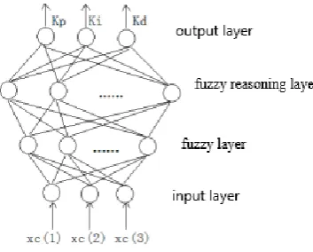
[image:3.595.212.389.216.358.2]The fuzzy control part of RBF network fuzzy PID control system mainly includes fuzzy mapping, rule space matching and composite mapping. The more input variables there are in RBF network, the more fuzzy neurons there are, and the higher the control accuracy of the system is. However, the more complex the fuzzy control rules are, and in practical programming, the fuzzy reasoning process is more difficult to realize. Figure 3. is shown structure of RBF fuzzy neural network.
Figure 3. Structure of RBF fuzzy neural network.
RBF network fuzzy PID control system adopts incremental PID controller, and the deviation input can be written:
(1) ( )
(2) ( ) ( 1)
(3) ( ) 2 ( 1) ( 2)
xc e k
xc e k e k
xc e k e k e k
(3)
The control quantity output can be given by function(3):
( ) ( 1) p( ( ) ( 1)) i ( ) d( ( ) 2 ( 1) ( 2))
u k u k K error k error k K error k K error k error k error k (4)
By comparing the ideal speed rin(k) with the actual speed yout(k), the corresponding error is obtained as the input signal to adjust system performance.
The first layer is input layer:
(1) ( ) (2) ( )
x rin k
x yout k
(5) The set speed rin(k) and the actual speed yout(k) are sent to the fuzzification layer as two input signals for fuzzy processing. In fact, the deviation error(k) is fuzzy processing.
The input of each node i in this layer can be expressed as:
1( ) [ 1, 2, 3]
f i X x x x (6)
The second layer is the fuzzification layer:
As follows: cij and bij are respectively the mean and standard deviation of membership degree of
the ith input variable and the jth fuzzy set.
2 1
2 2
( ( ) )
( , ) exp( ij )( 1, 2, , ; 1, 2, , )
ij f i c
f i j i n j n
b
According to the actual vehicle speed detected in the operation of the smart car, the PWM wave value corresponding to the average vehicle speed is about 50, and the center value of gaussian function corresponding to the input signal and output signal is {15,35,50,65,80} respectively. According to the actual detected speed distribution, corresponding to input signal and output signal is set as {30,30,40,30,30} respectively.
The fuzzy inference layer is the third layer.
Fuzzy inference layer and fuzzification layer are connected by fuzzy operation between two layers of neurons to achieve the correspondence of fuzzy rules. The fuzzy rule as:
If x1 is A and x2 is B, then u is C.
x1, x2 and u respectively represent the input quantity and output quantity. A, B and C respectively
represent their corresponding fuzzy quantity.
When center values of RBF gaussian function, the fuzzy relation can be synthesized into an inference algorithm , and the synthetic function of the fuzzy rule can be expressed as follows:
2 2
1 2
1 2 2 2
( ) ( )
( ) ( ) exp[ A ] exp[ B ]
A B
A B
x c x c
R u x u x
b b
(8)
Therefore, the fuzzy rules of fuzzy inference layer can be obtained from the above equation. The output of each node j is the product of all input signals of this node, namely:
3( ) 1 2( , )
N j
f j f i j ( 1 )
n i i
N N (9) The output layer is the fourth layer.
The fuzzy inference layer and the output layer are linearly connected, and the output layer function can be expressed as:
4( ) 3 1 ( , ) 3( )
N j
f i w f f w i j f j (10) Where: wij is the matrix composed of the weight coefficients between the output neuron and the
neurons in the fuzzy inference layer. The initial value of the connection weight is usually set to0.5 and adjusted according to the learning algorithm.
The output value of the output layer is Kp, Ki and Kd:
4 4 4 (1) (2) (3) p i d K f K f K f (11)
According to the quadratic form of the deviation between theoretical input rin(k) and actual output yout(k), judge whether the set Kp, Ki and Kd can make the optimal system control effect, and
judge the performance index as follows:
2 2
1 1
[ ( ) ( )] ( )
2 2
J rin k yout k error k (12)
Kp, Ki and Kd are adjusted according to the gradient steepest descent method:
( ) (1)
p
p p
E E y u y
K error k xc
K y u K u
(13)
( ) (2)
i
i i
E E y u y
K error k xc
K y u K u
(14)
( ) (3)
d
d d
E E y u y
K error k xc
K y u K u
(15)
of the performance index J to the weight coefficient w, and the inertia term is used to optimize the local convergence performance. Then:
( ) ( 1) ( )
j j j
w k w k w k (16)
Where,
( ) ( ) ( ) ( )
( ) ( 1) ( 1)
( ) ( )
j j j
j j
E k E k y k u k
w k w k w k
w y k u k w
(17)
( )
(( ( ) ( )) ( ) ( )
E k
rin k yout k error k
y k
(18) Jacobian matrix is ( )
( ) y k u k
, but because ( ) ( ) y k u k
is unknown, it is approximately replaced by a
symbolic function ( ) sgn( )
( )
y k u k
[5]
.
Then, the adjustment range of weight coefficient is:
3
( ) ( )
( ) ( 1) ( ) sgn( ) ( ) ( ( 1) ( 2))
( ) ( )
j j j j
j
J y k y k
w k w k error k xc j f w k w k
w u k u k
(19)
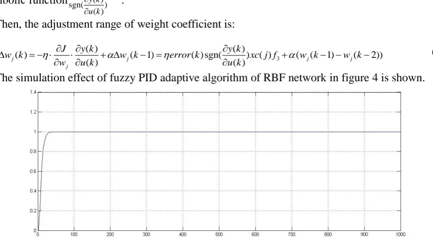
[image:5.595.74.520.257.506.2]The simulation effect of fuzzy PID adaptive algorithm of RBF network in figure 4 is shown.
Figure 4. Simulation effect of fuzzy PID adaptive algorithm of RBF network.
It can be seen from the simulation diagram that the control fitting effect of introducing the RBF neural network for optimization is better, not only without overshoot, but also quickly reaching the set speed. RBF network fuzzy PID adaptive control can theoretically optimize the performance of smart car speed control system to the best state, but the practical application reliability still needs to be improved.
Reference
[1] Shao Beibei. Learn to do smart car. Beijing university of aeronautics and astronautics press, 2007.
[2] Yan Yiyan. The rookie of camera device -- CMOS miniature camera [J]. Electronic world, 1999, (1): 47-47.
[3] Fritzke B. Fast learning with incremental RBF Networks[J]. Neural Processing Letters, 1994, 1(1):2-5.
[4] Liu Jinkun. Advanced PID control and MATLAB simulation. Electronic industry press, 2003. Tao yonghua, Yin yixin.