2018 3rd International Conference on Information Technology and Industrial Automation (ICITIA 2018) ISBN: 978-1-60595-607-7
An Active Phased Array Radar Transmitter
Design
Weiliang Gao and Baopeng Li
ABSTRACT
This paper presents an active phased array radar transmitter design using Injection-locking oscillators. The required phase relation for each array element is obtained by electronic tuning through injection-locking technique, and the beam-scanning capability is demonstrated, so a shifter less beam beam-scanning method is proposed.1
INTRODUCTION
Injection-locked technique[1] provides an efficient approach to generate stable high frequency signal source and finds its application in phase array. It can be used to achieved synchronous operation of a number of antenna elements, and allow for the manipulation of the phase distribution without additional phase shifting circuit. Hence, in modern microwave and millimeter-wave radar, imaging, and communication systems, the injection-locked technique is very suitable to be implemented for intelligent scanning antenna design.
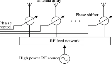
Principles of conventional phase array are well known, as shown in Figure.1[2]. Typically coherence is maintained between array elements using a single source distributed to every array elements through a corporate feed network. Separate phase shifters are required at each element, each of which requires biasing and multiple control wires. It is a challenge to collectively integrate antennas, feed networks, phase shifters, and control signals into a small package.
1
In this arrangement, components such as phase shifters may add considerable expense to the system. In addition, it is difficult to generate the required output power with a solid-state source at millimeter-wave frequencies. In this paper, an
Figure 1. Conventional phase antenna array.
active phase array with beam-scanning capability is designed using injection-locked oscillators. The necessary phase shifts are achieved via injection-locked technique.
THEORY OF INJECTION-LOCKING
The Injection-Locking Oscillator Technique
Injection locking oscillator was firstly examined by Van der Pol, and later by Kaneyuki Kurokawa. The main principle is based on the fact that any oscillator will be synchronized to an externally applied injected signal, if the free-running frequency is close to the signal’s frequency. The frequency of output signal is
inj
w w
, The phase of output signal is
inj inj
V V
Q sin
2 0
0
0 (1)
(1) is also called Adler equation. where is the phase of output signal,w0is the
instantaneous free-running frequency. Qis the quality factor of the tuning network,
inj
V
is the amplitude of the injected signal,V0is the amplitude of the free-running
signal. As a steady-state solution can be found for the phase such that =0, this indicates that the oscillator is synchronized to the injection signal. Solving for the
RF feed network P h a s e
control
antenna array
Phase shifter
High power RF source
steady-state phase differenceinjbetween the oscillator and the injection signal gives
) (
sin 1 0
m inj
w w w
(2)
(2) Indicates that an injection-locked is possible only the injected signal frequency lies within the locking range of the oscillator w0 wm. As the injected signal frequency is tuned over the locking range, the phase will vary with
90
90
. Therefore, one can acquire a phase-shifting operation by properly
tuning the VCO control voltage.
The Phase Array Using Injection-Locked Oscillators
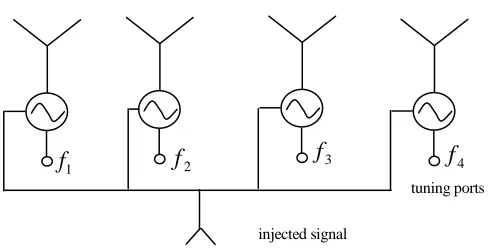
[image:3.612.186.434.449.575.2]Each array element is a self-contain VCO to deliver its energy to an antenna. Fig. 2 shows a phase array using VCOs and injection-locked technique. The oscillators are slaved to the injection signal, which can be distributed using a corporate feed network. Due to the non-uniformity of the devices the oscillation frequency of each VCO may be different. However, according to the theory of injection-locking oscillator, all the VCOs are locked and have the same frequency. We can change the phase of each oscillator by properly adjusting the oscillator tuning voltage, according to (2), to achieve required phase array operation.
Figure 2. Phase array based on 14 element injection-locking oscillators.
tuning ports
injected signal
1
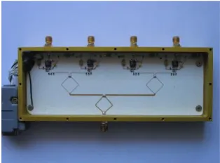
Figure 3. The 14 element active radar transmitter.
ACTIVE RADAR TRANSMITTER DESIGN
The antenna elements are designed using PM2503 which is an integrated oscillator and its operating frequency is 2-3GHz, Fig. 3 shows the schematic of the
oscillator unit and the photograph of a 14 element active antenna array. In Fig.3,
the output of VCO is connected with microstrip line whose characteristic impedance is 50. The material of PCB is 4350i which is made by Rogers company. The frequency tuning can be completed through L1. D1 is a varactor. C1,C2,C3,C4 are the capacitors which are used to remove the coupling.
EXPERIMENTAL RESULT
The theoretical predictions were tested using a 14 element injection-locking oscillators. The array used 0.762mm thick Rogers Ro4350B as substrate with r =3.48. The width and the length of each patch antenna were is 15.5mm and 20mm, respectively. The operating frequency is at 5GHz.
Figure 4. Experiment arrangement of a 14 element active phase array.
(a)
(b)
(c)
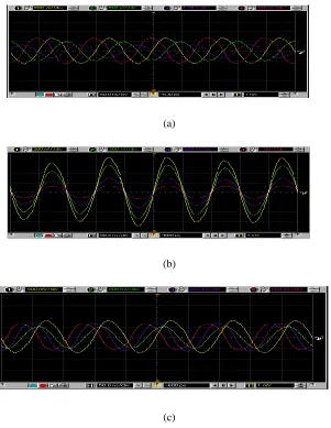
Figure 5. Waveform of phase difference of the 14 element phase array.
Signal Generator
Wilkinson Power Splitters
Mixer
Mixer Mixer Mixer
In
je
ct
io
n-lo
ck
in
g
os
ci
ll
at
or
s
[image:5.612.143.444.269.658.2]Adjusting the tuning ports to change each VCO’s free-running frequency, we can get the output waveform of each element. From the waveform, it is easily to watch the phase difference among the array. Figure. 5(a)-(c) shows the typical measured phase difference among the 4 elements. (a) is -45°(b) is 0°(c) is 45°.
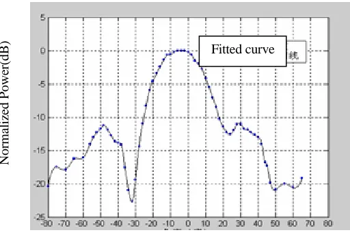
The measured scanning range is from -30.1°to 28.7°, Figure.6 shows the
measured radiation pattern of the 14 element phased array transmitter while the
[image:6.612.164.420.210.383.2]main beam is at 0°.
Figure 6. Radiation pattern of the 14 element phased array transmitter.
CONCLUSIONS
An active phased array radar transmitter is designed with its beam-scanning capability not using conventional phase shifter. The frequency synchronization and phase control are achieved by injection-locking technique. This kind of active phase array using injection-locking oscillators has many merits such as low cost high integration and high efficiency and it also can be applied to two-dimensional array.
REFERENCES
1. K. Kurokawa, “Injection Locking of Microwave Solid-State Oscillators,” Proc. IEEE, Vol, 61, No. 10, PP. 1386-1409, Oct. 1973.
2. J. Lin and T. Itoh, “Active Integrated Antennas,” IEEE Trans. Microwave Theory and Tech., Vol. MTT-42, No. 12, PP. 2186-2194, Dec. 1994.
Fitted curve
N
o
rm
al
iz
ed
P
o
w
er
(d
B
)