ISSN: 1992-8645 www.jatit.org E-ISSN: 1817-3195
CRANK ROUND SLIDER ENGINE MULTI-FLEXIBLE-BODY
DYNAMICS SIMULATION
1HONG-YUAN ZHANG, 2XING-GUO MA
1School of Automobile and Traffic, Shenyang Ligong University, Shenyang 110159, China 2School of Mechanical Engineering, Shenyang Ligong University, Shenyang 110159, China
E-mail: [email protected] , [email protected]
ABSTRACT
Based on multi-flexible-body dynamics theory, through the combination of finite element method software and multi-body system dynamics software, a multi-body system dynamics model of a crank round slider engine is established. In consideration of the influence of rigid-flexible coupling on the system, a dynamics analysis on a piston is performed to obtain displacement, velocity and accelerating curve of the piston as well as dynamic response in a period. The combination of a rigid body and a flexible body can achieve more intuitive and correct simulation of the actual working conditions of the engine, which provides an important evidence for the design and improvement of the engine.
Keywords: Multi-Flexible-Body Dynamics, Rigid-Flexible Coupling, Finite Element Method, Engine
1. INTRODUCTION
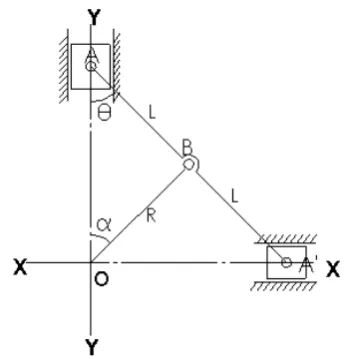
The crank round slider engine principle is shown in figure 1, the crank round slider engine consists of two pistons, two eccentric round sliders, a dynamic balance slider and a single crank, a connecting rod in a crank connecting rod engine is replaced by the eccentric round slider, and the dynamic slider substitutes for crank balance to play the role of balance. Because the crank and the connecting rod of the structural engine have equal lengths and the piston of particular structure is adopted, the stroke of the piston is 4 times that of the crank. An engine of the same volume has a stroke much bigger than a traditional engine, the piston does work on both sides and a crankcase is eliminated, so that the structure is reduced obviously with the advantages of simple structure, small volume, stable operation and so on.
[image:1.612.344.518.371.551.2]The piston of the crank round slider mechanism does movement according to sine law, inertia force thereof can be balanced easily by means of a movable balance block mounted on the crank. Therefore, the number of air cylinders can be reduced and the balance performance can be kept by increasing output volume of a single air cylinder of the crank round slider mechanism, thereby the number of movable members is reduced and the reliability is increased.
Figure 1. Working Principle Of Crank Round Slider Engine
ISSN: 1992-8645 www.jatit.org E-ISSN: 1817-3195
The text is based on the multi-flexible-body dynamics theory [1-5] ,it takes a crank round slider engine as the study object, establishes deformable dynamic equations through lagrange equation, describes the constrain of bodys by a set of algebraic constrain equations which depends on generalized coordinates, the algebraic constrain equations is introduced into dynamic equations by lagrange multiplier, obtained a set of mixed differential equations which including dynamic equations and constrain equations,it is the model in Consideration of Rigid-Flexible Coupling. Through the combination of finite element method software and multi-body system dynamics software, visualized dynamics simulation, a dynamic node equivalent stress curve and node equivalent stress nephogram during the operation of the engine can be determined more quickly and correctly.
2. MULTI-FLEXIBLE-BODY DYNAMICS
COMPUTATION MODEL
2.1. Mechanical System Dynamics Model in Consideration of Rigid-Flexible Coupling
The mechanical system dynamics model in consideration of rigid-flexible coupling can be obtained by establishing free-free movement equation of each sub-structure, exerting constraint of each sub-structure and external constraint on the system, and releasing the constraints by means of Lagrange multiplier:
Q
C
Kq
Cq
Mq
''
+
'
+
+
qTλ
=
(1)
( )
q
,
t
=
0
C
i(2)
Wherein M, C and K represent quality matrix, damping matrix and rigidity matrix of the mechanical system, Q represents generalized external force, Cq represents a Jacobi matrix of a system constraint (2), λ represents a vector of a Lagrange multiplier to be determined, CTqλ represents constrained force, q、q'、q'' represent
generalized coordinates, velocity and acceleration vector of the mechanical system respectively, wherein q may be represented to be:
[
q
1,
q
2,
q
i,
q
nb]
q
=
Wherein
q
i represents generalized coordinates of the ith individual in the system, and[
]
Ti i
x
y
z
q
=
,
,
,
ψ
,
θ
,
ϕ
⋅
⋅
⋅
⋅
⋅
⋅
⋅
⋅
⋅
⋅
⋅
⋅
⋅
=
mn m m n qC
C
C
C
C
C
C
2 1 1 12 11 Wherein j i ijq
C
C
∂
∂
=
m and n are number of constraint equations and number of generalized coordinates of the system respectively.
The solution of equations set (1) and (2) can obtain the time history of generalized coordinate vectorq q, namely, the time history of the generalized coordinate qi and generalized elastic
coordinate vector qif of nay object i in the system,
according to the physical meaning of
i f
q , a node
elastic deformation coordinate vector eijf on the jth element of object i can be obtained by means of a proper method, strain of any point in the element ij
can be obtained by the introduction of an element shape function sij.
ij f ij ij
p
=
s
⋅
e
ε
(3)
In the formula, ij p
ε represents a strain vector of any point p in the jth element of ith object in the system, sij represents a shape function of the element ij, which can be obtained by means of a interpolation function, the time history of ij
p
ε can be
used for computing the dynamic stress of the system structure through a stress-retain relationship.
Equation (1) is a set of rigid variable coefficient dynamics equations set. Equation (2) represents a constraint equations set between bodies in the system. The equations set is solved by a numerical solution and Newton-Raphson method of differential equations, the generalized acceleration
vector
q
''
can be represented as a function of generalized coordinates, velocity and time t.q
''
=
f
(
q
,
q
'
,
t
)
(4)
If
=
'
q
q
Y
ISSN: 1992-8645 www.jatit.org E-ISSN: 1817-3195
So
=
)
,
'
,
(
'
'
t
q
q
f
q
Y
(5)The above formula is the multi-flexible-body mechanical system dynamics computation model.
2.2. Establishment of Piston Flexible Body Model
[image:3.612.114.285.294.493.2]According to the constraint relationship of the piston and other members under ADAMS environment, three external nodes are defined in ANSYS, an ANSYS command cycle is worked out, the bearing area is rigidized by means of the beam4 element, and a model neutral file is generated by invoking ADAMS macro command. The generated piston flexible body model is as shown in figure 2.
Figure 2. Piston Flexible Body Model
Figure 3. Multi-Flexible-Body Dynamics Model Of The Engine
2.3. Multi-Flexible-Body System Dynamics Model of Engine
A three-dimensional entity model is established by means of SOLIDWORKS and introduced into ADAMS, the engine multi-rigid-body model is established by adding constraints and driving
In ADAMS/View, the rigid-body piston in the established multi-rigid-body dynamics model is replaced by a flexible-body piston, the
multi-flexible-body dynamics model as shown in figure 3 can be generated after exerting the explosion pressure and controlling the velocity of the crank
3. DYNAMICS SIMULATION
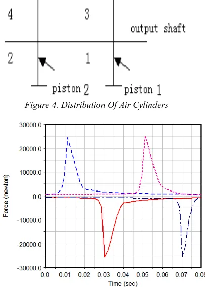
[image:3.612.325.528.319.603.2]4 air cylinders of the engine are distributed as shown in figure 4, when the engine is in operation, the explosion pressure of fuel gas acts on the end part of the piston continuously in turn according to the ignition sequence of 3-2-4-1, the reciprocating linear motion of the piston is converted into rotary motion of the crank through the crank round slider mechanism, fuel gas explosion pressure of each cylinder when the engine has a maximum torque speed of 1500r/min is exerted, and the engine is simulated for 0.08 seconds, the curves of fuel gas explosion pressure of each cylinder are as shown in figure 5.
Figure 4. Distribution Of Air Cylinders
Figure 5. Explosion Pressure Figure Of Each Cylinder Of The Engine
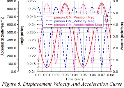
Curves of displacement, velocity and acceleration of the piston are as shown in figure 6, based on which we can see that the curves of displacement, velocity and acceleration of the piston are varied according to sine law.
ISSN: 1992-8645 www.jatit.org E-ISSN: 1817-3195
[image:4.612.91.308.179.729.2]model of the piston to obtain that the maximum stress of the piston in a working period is 1.6391MPa, which occurs at 0.0104 second when the cylinder 3 explodes and at a position where the stiffener of the piston is located, as shown in figure 7. At the same time, the variation in a working period of the maximum stress point of the piston in the whole period is given out, as shown in figure 8.
Figure 6. Displacement Velocity And Acceleration Curve Of Piston
Figure 7. Stress Nephogram Of Piston
Figure 8. Stress Variation Curve Of The Maximum Stress Point In The Whole Period
4. RESULT ANALYSIS
Through the simulation, it is found that in a working period the maximum stress of the piston occurs at a position where the stiffener of the piston is located and at a time when cylinder 3 explodes, the maximum VON MISES stress is 1.6391MPa, which is smaller than a yield limit 133MPa of piston material ZL108, so that the piston is in safe condition. From the curve as shown in Fig. 8, it can also be concluded that the stress of piston is close to the maximum value at the time when each cylinder explodes and the whole curve follows a cyclical pattern.
5. CONCLUSIONS
Through the establishment of the crank round slider engine multi-body system dynamics model in consideration of rigid-flexible coupling problem, displacement, velocity and acceleration curves of the piston are obtained, through multi-flexible-body dynamics simulation, a dynamic node equivalent stress curve and node equivalent stress nephogram during a working period of the engine are obtained. Combined simulation of ANSYS and ADAMS can achieve more intuitive and correct description of dynamic stress variation of the crank round slider engine in actual working conditions.
REFERENCES
[1] Lu Zhihua, “Computer simulation of dynamic response for flexible multibody mechnical system,” Hoisting and Conveying
Machinery. 1998; (7): 16-19.
[2] Hong Jiazhen, You Chaolan, “Advances in Dynamics of Rigid-Flexible Coupling System,”
Journal of Dynamics and Control. 2004; 2(2),
pp. 1-5.
[3] Lu Zhihua, Ye Qingtai, “Application of Flexible Multibody System Dynamics to Engineering Machinery Design,” Mechanical Science and
Technology for Aerospace Engineering. Xi'an.
1997; 16(4): 590-594.
[4] JIN Guo-guang, LIU You-wu, WANG Shu-xin, “Dynamic modeling on flexible rectangular plates system with large overall motion,”
Journal of Harbin Institute of Technology.
Harbin. 2009; 41(1): 239-245.
[image:4.612.92.305.194.344.2]ISSN: 1992-8645 www.jatit.org E-ISSN: 1817-3195
[6] Wang Y, Huston R L, “A lumped parameter method in the nonlinear analysis of flexible multibody systems,”Computers & Structures. 1994; 50: 421-432.
[7] Lu Youfang, “Dynamics of Flexible Multi-body Systems,” Beijing: Higher Education Press. 1996; 58: 58-108.
[8] Ider S K, Amirouche F M L, “Nonlinear modeling of flexible multibody system dynamics subjected to variableconstraints,”
Journal of Applied Mechanics.1989; 56:
444-450.
[9] Sharf I, “Geometric stiffening in multibody dynamics formulations,” Journal of Guidance,
Control and Dynamics. 1995; 18: 882-891.
[10]Mayo J, Dominguez J, “Geometrically nonlinear formulation of flexible multibody systems in terms of beamelements geometric stiffness,”