SELF-CONFIGURATION CONTROL TECHNOLOGY FOR
HVAC COOLING AND HEATING SYSTEM
JINMING YANG
College of Environmental Science and Engineering, Taiyuan University of Technology, Taiyuan 030024,
Shanxi, China
ABSTRACT
Relative to the traditional control techniques, self-configuration technology can bring many benefits for the HVAC engineers, building owners, construction managers and anyone associated with facilities management system. The key of this technology is the dedicated controller built-in general control software and friendly HMI (human-machine interface). The general control software uses the object-oriented programming techniques which based on packaged data models for both HVAC facilities and control instruments, and the models perfectly combine the process features and control features. This mechanism makes it very easy to build a control system for HVAC cooling and heating source system and has the enormous flexibility and adaptability. At the same time, the complex process of construct the control system does not need control experts to complete.
Keywords: Self-configuration, Data Model, HVAC Cooling and Heating System, Controller
1. INTRODUCTION
Generally, a good control system for cooling and heating source control system can only be completed finally by control experts who need to conduct comprehensive technical exchange with HVAC (heating, ventilation and air conditioning) professionals. Even so, the control system will still need to be tested and modified repeatedly.
Although a great deal of research has been conducted to improve the performance of control system by many technical specialists. But their focus is still how to improve the control strategies and control algorithms [5, 7, 8].
The key issue discussed in this article is how to build a control system based on self-configuration technology with simple and quick method. Due to the diversity and complexity of the HVAC cooling and heating source system, we will face many difficult challenges. What we should do first is to establish the general-purpose data model of HVAC equipment similar to the black-box. The equipment we discussed here includes not only process facilities (pumps, chillers, etc.) but also control instruments (sensors, electric actuators, etc.). The main feature of equipments data models is packaged equipment libraries which combine control features with the process features, and each library has both data structure and event handler functions. Secondly, we need to develop dedicated
controller built-in general-purpose control software on the basis of function library and object-oriented programming technique. At the same time, the controller has a good HMI to complete the self-configuration operation. Last, for nonlinear, large time delay, multi-variable characteristics of HVAC systems, traditional PID algorithm must be improved in order to meet the control system for HVAC applications, the fuzzy control or cascade regulation algorithms maybe the suitable choice. To achieve self-configuration all kind of suitable control algorithms should be integrated with the control software.
2. DATA MODEL OF HVAC EQUIPMENT
Due to the variety of HVAC equipment, we will discuss how to build the data model of HVAC equipment by using the water pump and chiller as facility examples, sensors as control instrument example. On the one hand we need to construct data model for HVAC facilities which combine the control features with process features, on the other hand combine the process features with control features of data model for HVAC control instruments.
2.1Data Model Example of Process Facilities
The data models are defined as follows (using c language for SCM):
Struct Pump {
Unsigned char Start_sequence; Unsigned char Shutdown_sequence Unsigned char Type_of_Equipment; Unsigned long RatedFlow_of_Pump [3]; Unsigned long RatedHead_of_Pump [3]; Unsigned char OnoffStatus_DigIN_Channel; Unsigned char OnoffControl_DigOUT_Channel; Unsigned char Freq_AnalogIN_Channel; Unsigned char Freq_AnalogOUT_Channel; }
The above definition describes the data structure of the pump, in which Start_sequence and Shutdown_sequence indicate its start-up and shutdown order. Type_of_Equipment represents the type of pump, such as cooling water pump or heating primary pump, RatedFlow_of_Pump [3] and RatedHead_of_Pump [3] describes the performance parameter of pump. These variables mentioned above are all process features of pump, and the other four variables are the control features of pump. The variable OnoffStatus_DigIN_Channel represents the feedback channel of pump running status, OnoffControl_DigOUT_Channel represents ON-OFF control channel, Freq_AnalogIN_Channel represents the pump operating frequency feedback channel, and Freq_AnalogOUT_Channel represents the pump operating frequency regulation channel.
The event response functions of the pump list as follows. Due to the complexity of the mechanism the article will not discuss in detail.
Void Pump_ON ( ); Void Pump_OFF ( );
Void Pump_Fault_Handle ( ); Void Pump_Frequency_Change ( );
Pump function library implements runtime response to various events, such as pump on-off control and fault handling.
Similarly, chiller data structure is defined as follows, and this article will not discuss the function of the chiller. With the help of data structures, HVAC process facilities obtain control features.
Struct Chiller {
Unsigned char Start_sequence; Unsigned char Shutdown_sequence Unsigned char Type_of_Equipment;
Unsigned char OnoffStatus_DigIN_Channel; Unsigned char OnoffControl_DigOUT_Channel; Unsigned char Load_AnalogIN_Channel; Unsigned char Load_AnalogOUT_Channel;
}2.2 Data Model Example of Control
Instruments
We use sensors as an example to describe its data model for self-configuration purpose.
Struct Sensor_Channel {
Unsigned char Sensor_Type;
Unsigned float Upper_Limit_Measure; Unsigned float Lower_Limit_Measure; Unsigned float Upper_Limit_Alarm; Unsigned float Lower_Limit_Alarm; }
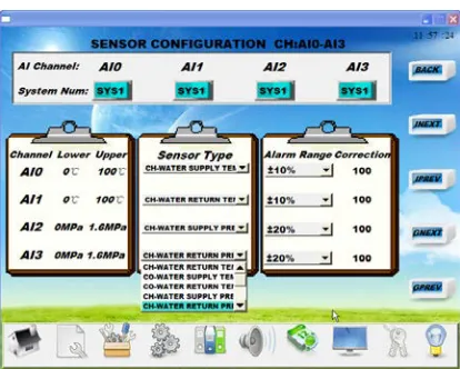
The most important parameter in the above data model is Sensor_Type. For the temperature sensor of the control system commonly used, it has the general control attribute, and configurated by the control professionals when it is used by actual project. Now various sensors applied to control system for HVAC cooling and heating source system could be categorised into 42 kinds, for example chilled water supply temperature sensor, chilled water return temperature sensor, primary water supply temperature sensor, secondary water supply temperature sensor, chilled water flow rate sensor etc. The engineering staff only selects the type of sensor and configuration for sensor is completed.
In this way, general sensors obtain the process features.
2.3 Acquisition of Data Models
The package of data and events handling functions is a prerequisite for realization of self-configuration, and the above examples show that technical staff familiar with expertise in both HVAC field and control field must summarize and refine the data model from the massive project practice. Process features and control features of HVAC equipment unify perfectly in together through the data model, and this is the basis for developing general-purpose control software.
3. DEVELOPMENT OF DEDICATED
CONTROLLER
In order to achieve the self-configuration, it is necessary to develop a dedicated controller which has more advantages relative to the general– purpose controller. With the help of the control-system demands analysis, a dedicated controller for self-configuration is developed and its main performance parameters are listed as follows:
1) High operating speed of CPU;
2) 16-channels digital input and 16-channels
3) 11-channels 12 bits analog input and 4-channels 12 bits analog output;
4) Touch-screen interface;
5) RS232 and RS485 industrial standard
communicate interface;
It is necessary to develop hardware driving function library. The library includes all driving functions designed for chips on control board, such as analog input function, analog output function, digital input function, digital output function, RS232/RS485 communication protocol functions and IIC-bus driving function, etc[3].
4. DEVELOPMENT OF CONTROL
SOFTWARE FOR SELF-CONFIGURATION
For HVAC dedicated controller, the control software is even more important than hardware. Control software is composed of two parts, one part is generl-purpose control software, and the other is HMI interactive software. Generl-purpose control software is the core of self-configuration control system, and HMI interactive software is self-configuration operating platform. Based on the data model mentioned above, the process facilities and control instruments are all organized by using their function library, furthmore form a specific control systems for HVAC cooling and heating source.
Each facility should have its corresponding control strategy to meet the system requirements, but has the similar control method in view of different systems, such as ON-OFF control, capacity control and safety interlock control. Therefore general control strategy function must be developed firstly. For control strutments, they will have specific meaning when they are applied to a specific project and configurated by control professionals. For example, all temperature sensors are the same, a kind of general temperature measuring device. But they can be divided into different types when used in HVAC cooling and heating system, such as chilled water supply
temperature sensor, chilled water return
temperature sensor, cooling water supply
temperature sensor, etc. Thus all the temperature sensors have the specific features. The events handling function relative control instruments may include data-quisition, scale conversion and alarm. Different functions of measurement and control for different control instruments are necessary [1, 2].
In addition, in order to realize the self-configuration the control system must supply friendly HMI software which provides the standard way to achieve human-machine interaction.
[image:3.612.312.523.110.449.2]Self-configuration pictures example below describes this method.
[image:3.612.314.522.115.282.2]Figure 1: The Chillers Configuration Picture
Figure 2: The Sensors Configuration Picture
The Figure 1 is chiller configuration picture and Figure 2 is sensors configuration picture. All configuration pictures are displayed on touch screen integrated with controller and could be completed by general technicians. The technical staff and operators can decide by themselves how to configure control features and process features of HVAC equipment and how to construct the control system for their cooling and heating system, therefore this way of configuration is called self-configuration. The self-configuration could be realized on site without reprogramming by control professionals, and general configuration for control system need professionals to complete the process by using computer programming.
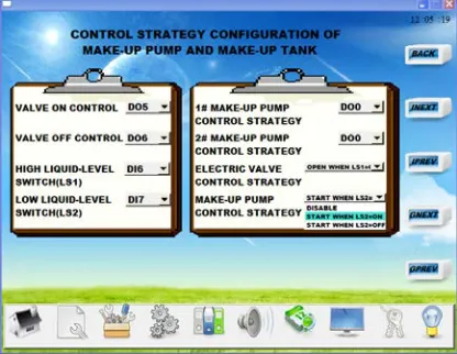
[image:3.612.314.521.298.464.2]correlation functions to realize control strategies, such as heating or cooling load calculation function which is used to solve real-time building load, HVAC equipments control function which decide how and how many equipments put into operation, and synchronous frequency conversion function for multi-pumps system which can bring not only more energy-saving benefits but also lower risk of over load, and so on. These dedicated control strategies functions play an important role for HVAC control system. All of those greatly reduce the difficulty of the control system construction. The configuration method of control strategies is illustrated in Figure 3 below.
Figure 3: The Control Strategies Configuration Picture
The Figure 3 gives the outline of constructing feed-water control system with strategy configuration. According to configuration result, the make-up pump will start when the low liquid-level switch feedback is on and shutdown when switch feedback is off, water supply electric valve will open when the high liquid-level switch feedback is off and close when switch feedback is on. These control strategies would meet the control requirement of feed-water system, and could be changed by technical personal. Actually the different choices of strategies decide how control system work, and functions of control software provide the support. This makes it possible to generalize control software.
5. PROJECT EXAMPLE
The article will illustrate the self-configuration method with an example of actual project. HVAC cooling and heating source system for a building consists of two screw chillers, two cooling towers, three chilled water circulation pumps, three cooling water circulation pumps, two make-up water pumps and make-up water tank. All types of sensors and
electric actuators are installed for measurement and control.
[image:4.612.313.521.325.486.2]Control features and process features of all equipment are defined with self-configuration, includes number and type of each equipment, status feedback and control channels. Then we can define the control strategies of the cooling and heating system, such as system start-up and shutdown interlock control strategy, variable flow control strategy for both chilled water system and cooled water system, control strategy for make-up pump and make-up tank, all of these are defined by self-configuration technology. Last we can define control algorithms in this same way. Control system would be put into operation after configuration for the system completed. The Figure 4 below shows the running picture sample of HVAC cooling and heating system by using self-configuration [4].
Figure 4: The Running Picture
6. CONCLUSION
It is very significant to develop a new way of constructing control system for HVAC cooling and heating source. Self-configuration technology discussed in the article maybe a suitable method.
The article describes the rationale and
build control systems. In short, the self-configuration technology provides great convenience for the system design, construction and debugging. This article just made some tentative study on the advanced technology maybe helpful for those researchers who want to improve control system for complex HVAC cooling and heating system.
REFERENCES:
[1] Jinming Yang, Yi Lin, “Control algorithms and control strategies for variable primary flow
chilled water systems”, Proceedings of the 2012
International Conference on Computer
Application and System Modeling, 2012, pp.
634-637.
[2] Jinming Yang, “Fuzzy control for variable
cooling water flow system”, Proceedings of the
2012 International Conference on Building
Materials and structural Engineering, Trans
Tech Publications Ltd, March 19-20, 2012, pp. 105-108.
[3] Jinming Yang, Yi Lin, “Development of
dedicated controller for HVAC”, Proceedings
of the 2012 International Conference on
Frontiers of Advanced Materials and
Engineering Technology, Trans Tech
Publications Ltd, January 4-5, 2012, pp.
1472-1479.
[4] Jinming Yang, “Variable flow technique for
heating circulating pump”, Proceedings of the
2010 International Conference on Computer
Application and System Modeling, IEEE
Conference Publishing Services, October 22-24, 2010, pp. 1307-1310.
[5] Soyguder Servet, Karakose Mehmet, Alli Hasan, Design and simulation of self-tuning PID-type fuzzy adaptive control for an expert HVAC
system”, Expert Systems with Applications, Vol.
36, No. 3, 2009, pp. 4566-4573.
[6] French Jonathan C, “Object-oriented
programming of HVAC control devices”, ASHRAE Journal, Vol. 33, No. 12, 1991, pp. 33-41.
[7] Hartman, Thomas, “New horizons for HVAC
control”, Heating Piping Air Conditioning, Vol.
67, No. 3, 1995, pp. 33-41.
[8] Mulcahy, Robert W, “New developments in HVAC control systems and the impact ofdirect
digital control technology”, Australian
refrigeration, Air conditioning and heating,