702
A FLEXIBLE VITERBI DECODER FOR SOFTWARE
DEFINED RADIO
LI ZHOU,MIN TANG, DONGPEI LIU, HENGZHU LIU
Institute of Microelectronics & Microprocessor, School of Computer Science, National University of
Defense Technology, Changsha 410073, Hunan, China
ABSTRACT
Modern wireless communication standard varies a lot from each other and is evolving rapidly. Flexibility becomes the dominate consideration of software defined radio (SDR) system design. Reconfigurable platform is preferred in the SDR due to the reuse of hardware. Convolutional code is widely adopted in many wireless protocols but the code parameter differs. In order to support multi-standard service, a decoder compatible for different protocols is needed. In this paper, we designed a flexible Viterbi decoder which is compatible with WiMAX, UMB and LTE’s channel coding scheme. High efficient cascaded Add-compare-select unit architecture and sliding window method for trace back are presented. Meanwhile, conflict free memory access model is also given. FPGA prototype shows our design is highly flexible while maintaining a high throughput with low area cost compared to others.
Keywords: Viterbi Decoder, Flexible Architecture, Software Defined Radio
1. INTRODUCTION
In recent years, many wireless protocols have been widely applied and new standards are emerging increasingly. The incompatibility of these standards increases the cost of seamless communication both on user and service provider. Thus, flexibility is required in future mobile communication system and the concept of software defined radio (SDR) becomes popularity. SDR supports implementing multi-mode communication on a general hardware platform [1]. Usually, SDR is composed by reconfigurable hardware which can be reprogrammed to gain flexibility for various wireless protocols. Compared to tradition systems, SDR satisfies the requirement of multifunctional in different time and context by upgrading configuration running on the hardware platform. SDR also shortens time to market of new product.
Channel coding is a significant part in the wireless protocols. It protects information from impairments during transfer. Convolutional code is an efficient coding scheme due to its low latency and better performance compared to block code [2]. It has been commonly used in the 3G and 4G wireless standards. However, different code parameter is selected in different standards for the consideration of channel characteristic, code rate and bit error rate requirement. As showed in Table 1, the constraint length, code rate and polynomial of convolutional code various a lot. So, the decoder in
[image:1.612.308.530.402.469.2]SDR itself should accommodate for the reconfigurability to support the standards desired.
Table 1: Code Parameters Of Different Standards
Standard
Code parameters
Constraint
length Code rate Polynomial WiMax 7 1/2 (171, 133)oct
UMB 9 1/3 (577, 633, 711)oct LTE 7 1/3 (133, 171, 165)oct
In this paper, we present a Viterbi decoder with highly flexibility which can deal with convolutional code of constraint length from 5 to 9, code rate 1/2, 1/3, 1/4 and user defined polynomials.
2. VITERBI DECODER REVIEW
ISSN: 1992-8645 www.jatit.org E-ISSN: 1817-3195
703
Figure 1: (A) A Convolutional Encoder (B) Trellis Of The Code
Generally, a Viterbi decoder consists three parts [3]:
(1) Branch Metric Calculation Unit (BMCU). It computes the Euclidean distance of received signal and the output data of corresponding branch in trellis. The distance is also called branch metric.
(2) Add Compare Select Unit (ACSU). It operates the ‘butterfly’ computation (the black line in Fig 1b) and finds survival path. There is a metric for state i at time t, denote by i
t
S . It is calculated by adding branch metric to the metric of its previous state, and then the path which has smallest metric that entered into the state is selected.
(3) Survival Path Management Unit (SPMU). It stores the result of survival path selection and generates the path’s output from the selection.
The BMCU is quite simple and does not have much influence on the performance. Thus, our decoder does not contain BMCU and takes the calculated branch metric as input. The constraint length varies from 5 to 9, which means the number of states at each stage varies from 16 to 256. This makes code trellis and the computation pattern on ACSU more complex [11]. We designed a fast cascaded ACSU with delicate scheme of access state metric memory to sustain various code parameters. For the SPMU, either ‘register exchange’ or ‘trace back’ method can be adopted [4] [10]. The register exchange method is suitable for low complexity, fixed trellis. In the configuration of our parameter, the large number of state and user defined polynomial make code trellis too complicated and variable. It will consume a lot of wire resource and increase power consumption in register exchange method. So the SPMU of proposed Viterbi decoder is based on the trace back method. We apply a sliding window scheme to exploit parallelism between ACSU and SPMU to decrease decode latency.
3. PROPOSED DECODER
The core architecture of proposed Viterbi decoder for multi-standard is depicted in Figure 2. The ACSU is composed by a cascaded ACS for butterfly computation, a state metric memory and its write/read address generation subsystem. The SPMU is composed by a survival path memory, a trace back logic and control logic of memory write/read for sliding window trace back scheme.
Code parameter
Cascaded ACS
State Metric RAM
RAM Addr Gen
Control TraceBack
Surviaval Path
RAM RAM
Read/Write Control
Branch Metric Input
Decode Output Survival Path
Information
Data Path Control Path
Figure 2: Architecture Of Proposed Viterbi Decoder
3.1 Add Compare Select Unit
We designed a cascaded ACSU by connecting the state metric computation of next stage together with current stage, which means we update state metric for two stages once a time. The diagram of cascaded ACS is showed in Figure 3 where
1
2K
M = − and K is constraint length.
ACS0
ACS1 ACS3
ACS2
Si+1t Sit
Si+2 t
Si+3 t
S St+1i/2
i/2+M/2
Si/2+1
Si/2+M/2+1 t+1
t+1
t+1
Si/4+M/4 Si/4t+2
S
S t+2
t+2
t+2 i/4+M/2
i/4+3M/4 Branch Metric
Selection Branch Metric
Input Code Paramter
[image:2.612.321.533.218.312.2]Branch Metric State Metric
Figure 3: Diagram Of The ACSU
[image:2.612.324.504.403.589.2]704 The proposed architecture can reduce the frequency of memory access because write and read operation are needed only once per two stage. The trace back procedure can also be accelerated for each trace operation generates two symbols. Although several advantages that cascaded ACS can get, further cascading more ACS is not a good choice because the calculation of next stage has to be stalled until the required state metric is updated by previous ACS. Besides, a lot of registers are needed for storing metric that not yet used, which brings latency in data path and complexity in control path [6].
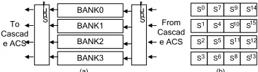
3.2 Conflict Free Memory Access
Another important feature of the ACSU is the arrangement of state metric in memory and the address generation subsystem. They ensure the correctness of decoder for all constraint length. Figure 4 shows the memory organization and an example of data arrangement at K=5.
BANK0 BANK1 BANK2 BANK3 S S S S S S S S S S S S S S S S 0 1 2 3 7 4 5 6 9 10 11 8 14 15 12 13 S hu ffl e S hu ffl e To Cascad e ACS From Cascad e ACS (a) (b)
Figure 4: (A) 4 Bank State Metric Memory (B) Data Arrangement
Due to the data supply requirement of ACSU, we divide RAM into four banks. The in-place schedule is applied which means updated metric will store at the location of its previous metric [7]. The data arrangement for each code parameter must ensure that conflict of memory operation does not exist. Shuffle logic is added at input and output ports of RAM for the reason that each bank may not directly provide data to its ACS when conflict avoided strategy is applied. By observing the concurrently fetched and stored data of cascaded ACS, we note that and can be put into the same bank only if the equation (1) is satisfied.
3
mod 2K / 4 / 4
i≠ j − ∧i ≠ j (1)
A feasible scheme to place state 0 to 255 in state metric memory is found by computer search. The arrangement for K=5 is showed in Figure 4(b). A lookup table from state id to its address in memory is built in ROM so that we can quickly find the location of through its state id.
The address generation logic is implemented by circular shift of state id. The procedure can be exemplified by Figure 5.
[image:3.612.316.520.69.226.2]S S S S S S S S S S S S S S S S 0 1 2 3 7 4 5 6 9 10 11 8 14 15 12 13 S S S S S S S S S S S S 1 5 9 6 10 14 2 11 15 3 7 13 After 2 stage caculation S S S S 0 4 8 12 S S S S 0 1 2 3 S S S S 0 8 1 9 S S S S 0 4 8 12
Figure 5: State Metric Memory Address Generation Example
According to the code trellis, state 0, 1, 2 and 3 generate state 0, 4, 8 and 12 after butterfly operation. The in-place schedule makes the location of state 0, 1, 2 and 3 stores the state 0, 4, 8 and 12 afterwards. Other transformations can be derived similarly. The data map of state memory after calculation is depicted in Fig 5. In next two stages, the read address of state 0, 1, 2, and 3 can be generated by look 0, 4, 8, 12 at lookup table before fetching. A shifter completes this task at the end of every two stages by right circular shifting the state id. Then shifted state id is sent to lookup table to generate the correct address for next memory read operation.
3.3 Survival Path Management Unit
Usually, the trace back operation starts when the whole frame ACS completed, and the latency grows with frame length. Splitting the frame into sliding windows will reduce latency and exploit parallelism between neighboring windows. Trace back operation will start from where sliding window ends. Thus, the survival path memory is composed of two RAM, each RAM stores a window. One can receive survival path information from ACSU while the other one is providing data for trace back in a ping-pong way.
[image:3.612.106.294.335.388.2]ISSN: 1992-8645 www.jatit.org E-ISSN: 1817-3195
705
Window Length
R C
[image:4.612.96.288.72.186.2]ACS operation Traceback operation
Figure 6: The Sliding Window Method
The convergent part in previous window belongs to the reliable part in next window. So, the survival path information of each convergent part must be written into both RAM for it will be used in two neighboring windows. The ping-pong RAM for survival path must have a special status when convergent part is written.
The whole procedure is described as follows: (1) Write reliability part of window 1 to RAM A. (2) Write convergent part of window 1 to both RAM A and RAM B.
(3) Switch RAM A and B so that RAM B receives reliable part of window 2 from ACSU meanwhile RAM A provides data for trace back operation of window 1.
(4) Write left reliable part of window 2 to RAM B and then write convergent part of window 2 in both A and B when trace back of window 1 is finished.
(5) Switch RAM A and B for next window.
Figure 7(a) shows the survival path memory architecture and Fig 7(b) illustrate the procedure of how ACSU and SPMU work in parallel.
We can see that the sliding window method greatly reduced the decoding latency because parallelism between ACSU and SPMU is utilized.
W rit e C on tr ol
R ea d C on tr ol
RAM A
RAM B From
ACSU TracebackTo
C R - C C
R R+C 2R+C 3R+C
Symbol
Time (a)
(b)
Convergent traceback ACS operation
Reliable traceback
W1 W2
Figure 7: (A) Survival Path Memory Architecture (B) ACS And Trace Back Operations With Sliding Window
4. IMPLEMENTATION AND EVALUATION
After designing the decoder architecture, we implemented it with Verilog HDL and done a fast prototype on FPGA. This section will show the implementation and evaluation result.
[image:4.612.311.524.272.439.2]We have implemented the Viterbi decoder in FPGA to verify the correctness and evaluate the performance of decoder. All FPGA experiments are done in Xillinx Virtex II XCV2000 FPGA. Table 2 shows the FPGA implementation comparison of the proposed decoder and other design. The results of our decoder are generated for ISE tools after place and route process.
Table 2 : Table Parameters
[8] [9] Proposed decoder Supported
code parameter
Only support
K=7,rate =1/2 UMTS,GPRS
WiMAX, UMB, LTE
FPGA type XC3SD3400A XCV2000 XCV2000
Slices 983 3501 3444
4 input
LUTs 1378 8170 6303
Block
RAMS 2 33 8
Maximum
frequency 172MHz 32.256MHz 65.933MHz Maximum
decode bit rate at
7
K=
15Mbps 8.064Mbps 8.242Mbps
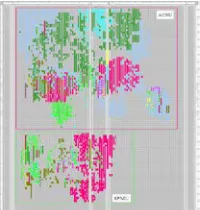
According to table II, our design is highly flexible while maintaining a high throughput. The area consumption is also reduced compared to [9]. Two reasons may contribute to this performance: first, the structure of our cascaded ACSU is very efficient for different code parameter; second, we applied sliding window method to reduce the latency. Figure 8 is the layout of proposed Viterbi decoder in FPGA XCV2000.
Figure 8: FPGA Layout Of Proposed Viterbi Decoder
5. CONCLUSION
[image:4.612.103.281.543.700.2] [image:4.612.373.473.556.661.2]706 communication. The decoder can deal the convolutional code in wireless standard WiMAX, UMB, LTE and etc. It is reconfigurable and suitable for software define radio platform. The proposed architecture is highly efficient when handling different code parameter. The strategy we applied in ACSU and SPMU made a good trade off between performance and flexibility. Further optimization and implementation in ASIC design will meet the data rate in future mobile systems.
ACKNOWLEDGEMENTS
This work was supported by National NFSC of China (06970037).
REFERENCES:
[1] W. H. W. Tuttlebee, “Software-defined radio: facets of a developing technology”, IEEE Personal Communications Magazine, Vol. 6, No. 2, 1999, pp. 38-44.
[2] G. Forney, “Convolutional codes II. Maximum-likelihood decoding”, Information and Control, Vol. 25, No. 3, 1974, pp. 222-266.
[3] M. Irfan, et al., “Design and Implementation of Viterbi Encoding and Decoding Algorithm on FPGA”, Proceedings of the 17th International Conference on Microelectronics, December 13-15, 2005, pp. 234-239.
[4] D.A.F. El-Dib, M.I. Elmasry, “Low-power register-exchange Viterbi decoder for high-speed wireless communications”, Proceedings of IEEE International Symposium on Circuits and Systems, IEEE Conference Publishing Services, May 26-29, 2002, pp. 737–740. [5] P. J. Black and T. H. Meng, “A 140-Mb/s,
32-state, radix-4 Viterbi decoder”, IEEE Journal of Solid-State Circuits, Vol. 27, No. 12, 1992, pp. 1877-1885.
[6] D. Yeh, et al., “RACER: a reconfigurable constraint-length 14 Viterbi decoder”, Proceedings of IEEE Symposium on FPGAs for Custom Computing Machines, IEEE Conference Publishing Services, April 17-19, 1996, pp. 60-69.
[7] W. Ching-Wen and C. Yun-Nan, “Design of Viterbi decoders with in-place state metric update and hybrid traceback processing”, Proceedings of IEEE Workshop on Signal Processing Systems, IEEE Conference Publishing Services, September 26-28, 2001, pp. 5-15.
[8] Xilinx Corporation, “Viterbi decoder: product specification (v6.2)”, October, 2007.
[9] L. Bissi, et al., “A Viterbi decoder architecture for a standard-agile and reprogrammable transceiver”, Integration-the VLSI Journal, Vol. 41, No. 2, 2008, pp. 161-170.
[10] Y. Gang, T. Arslan, and A. T. Erdogan, “An efficient pre-traceback approach for Viterbi decoding in wireless communication”, Proceedings of IEEE International Symposium on Circuits and Systems, IEEE Conference Publishing Services, May 23-26, 2005, pp. 5441–5444.