DEVELOPMENT AND PRINCIPLE OF CONTINUOUSLY
VARIABLE TRANSMISSION HARDWARE IN THE LOOP
SIMULATION SYSTEM
1LEI ZHANG, 2JIN DAI , 3XIUMIN YANG , 2TAO WEI 1
Assoc. Prof., School of Mechanical Engineering & Automation, Northeastern University, P.R.CHINA
2Graduate, School of Mechanical Engineering & Automation, Northeastern University, P.R. CHINA
3Prof., Department of Automatic Control, Shenyang Engineering Institute, P.R. CHINA
E-mail: [email protected],[email protected],[email protected]
ABSTRACT
HILSS (Hardware in the loop Simulation System) is a safe off-line virtual test system that will meet off-line test requirements, reduce development costs and shorten the test cycle. Traditional development methods of the control system will be changed by HILSS, which has been considered as an advanced simulation technology and a convenient method. The construction and development of HILSS of CVT (Continuously Variable Transmission) for vehicles are presented in this paper. The structure and principle of CVT HILSS are analyzed, then the engine model is built based on the engine data of bench test and the best economic and the best dynamic curves of the engine are drawn. The clutch model and the speed ratio control model are built based on the actual structure of the CVT. These models are verified to be practical by the Matlab/Simulink. At last, HILSS platform is built which can make debugging and development of the control system a reality.
Keywords: Vehicle CVT, HILSS, Modeling, System Development.
1. INTRODUCTION
Power transference of CVT depends on the combination of the transmission belt and the driving and driven wheels with variable working diameters. This makes the continuous change of the transmission ratio to reality, gets the best match of the transmission system and engine condition, and makes the vehicle more economical, comfort and powerful. Power transference of CVT depends on the combination of the transmission belt and the driving and driven wheels with variable working diameters. This makes the continuous change of the transmission ratio to reality, gets the best match of the transmission system and engine condition, and makes the vehicle more economical, comfort and powerful.
However, the development of CVT control inefficiency, high risks and little effects in some extreme system needs long periods of bench tests and vehicle tests, which are considered as long periods, high costs, inefficiency, high risks and little effects in some extreme conditions. Therefore, a safe off-line virtual test system is needed which
could meet the test requirements, shorten the test cycle and reduce the costs.
At present, the hardware in the loop simulation is mainly applied in some large car companies and researched by related universities. Especially, the hardware in the loop real-time simulation method is widely used, and a group of mature technology can be selected for the development of control systems. Currently, many foreign companies have launched control system development tools which can be used in various fields, and mainly in the following forms:
The first form is multi-processor system which is composed by commercialization processor templates. Developers design special interface templates independently and use common software development tools such as C language compiler, assembler compiler, etc, to develop the software program.
the VME bus, and can be connected into the LAN. The communication processor (COP) services for the communication between all processors on the bus. Its main task is data diffusion and collection. However, the whole system is complex, and the price is high.
The third form is xPC-Target. It needs an ordinary computer as the processor, and uses the xPC module in MATLAB / Simulink to develop. The xPC-Target provides some convenient tools for hardware-in-the-loop simulation and can achieve most functions of hardware in the loop simulation. However, some hardware and experimental software of the xPC-Target need to be selected and developed independently.
The fourth form is one kind of hardware system which is produced by DSPACE Company for real-time simulation and high-speed I/O processing. It utilizes a distributed processor architecture based on the ISA bus, uses a DSP chip as the high-speed computing unit, and has intelligent I/0 interface modules. The dSPACE real-time system has a hardware system which can make high-speed computing and a software environment which is easy to use for real-time code generation, downloading, experimentation and debugging.
However, no matter what kind of hardware in the loop simulation only provides a common simulation developing platform, and the secondary development should be done. This paper builds the hardware in the loop simulation system (HILSS) which is a virtual test system that can meet off-line test requirements of automotive CVT. As a advanced simulation technology, HILSS can change the traditional methods of the development of
control systems. The off-line testing and evaluating of the vehicle control system can be done by using the HILSS to simulate the actual operating conditions of the vehicle, and a convenient way for the development of control system is provided.
2. STRUCTURE AND PRINCIPLE OF CVT HILSS
Due to the different traffic conditions, the vehicle’s speed and drive torque need to be changed in a wide range. However, the changing range of the engine speed is small, and the changing range of the torque cannot meet the traffic condition needs. Therefore, a CVT is needed. The control task of EMCVT is to meet the vehicle’s power requirements, meanwhile, to make the engine work in the best economic mode or dynamic mode. This requires the control system to take full account of the various road conditions and driver’s needs of driving, to adjust the transmission ratio timely according to the change of throttle opening degree, and to make the engine maintain the best working conditions. Therefore, EMCVT’s control tasks can be summed up for the following two points. Firstly, the controls of the speed ratio motor, namely the controls of the transmission ratio. Transmission’s main task is to change the transmission ratio. The change of the EMCVT’s transmission ratio is determined by the position of the cone. The position of the cone is controlled by the external speed ratio control motor. Therefore the speed ratio control motor lets the transmission match with the engine, and make the engine maintain the best working conditions. Secondly, the controls of the clutch motor. Clutch pedals are canceled in EMCVT automobiles. The clutch is controlled by the clutch
Speed of CVT output shaft Engine speed Axial displacement of the
driving plate Angular displacement Of
clutch control motor Throttle opening
Data acquisition
card Stalls
Brake
Data acquisition
card
Control signal of clutch motor
Control signal of speed ratio control motor Computer
simulation models
[image:2.612.183.428.519.711.2]TCU
motor. The task of clutch controls is to make the clutch reliably transfer the engine torque, and to ensure the engine will not turn off when the vehicle starts up and brakes.
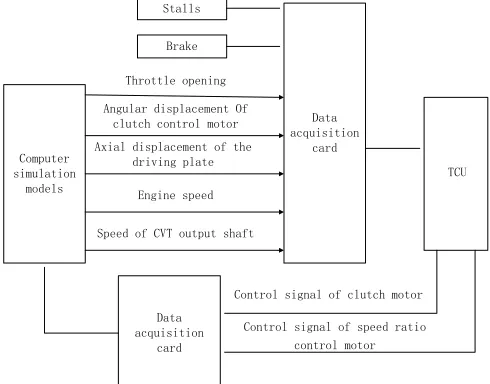
HILSS consists of three parts: computer, system simulation models and actual hardware interface module. The computer simulation models are mathematical models based on field test environment. It runs in according to the instructions provided by the control system that will be debugged and outputs corresponding performance parameters: It consist of engine model, clutch model and the speed ratio control model, etc. Actual hardware interface module is an interface device, and HILSS accepts external commands and outputs model parameters through it. It can achieve various signal transmission between simulation models and control box. It consists of data acquisition card and relevant functional modules.
Principle of HILSS is shown in Figure 1.
3. HILSS MODELING
In the process of the establishment of CVT HILSS, simulation models are used instead of a
engine and a transmission, and physical real-time simulation process is used for control system. Engine model, clutch model and speed ratio control model in simulation system are constructed and linked by operating parameters and control parameters, to form a CVT vehicle simulation model.
Engine model. The engine mathematical model established in this paper is based on field trials with the experimental data of the Dongan Engine, for the control system debugging of engine experimental data of HILSS.
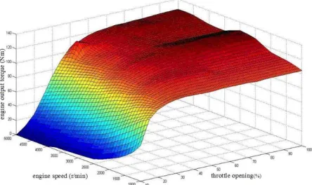
Engine torque model. Analysis of engine experimental data and the experiences shows that the change of engine steady-state output torque is a binary function of throttle opening and engine speed, namely:
T = f( ,n)
α
(1)Where
T
is engine steady-state output torque,α
is throttle opening,n
is engine speed. [image:3.612.172.506.397.732.2]The output torque model related with throttle opening and engine speed is constructed according to formula (1), which is shown in figure 2.
Fig. 2 Model Of Engine’s Output Torque
[image:3.612.204.426.415.547.2]Most of the time, the engine works in dynamic conditions due to the changes in road conditions that result in the various changes of speed and resistance that cause a corresponding change of engine speed and load. So correction factor is used here to correct the engine steady-state output, and to obtain the dynamic-state output torque of the engine:
e e
T = T(1 -
λω
)
(2)e
T
is the dynamic-state output torque of theengine,
T
is steady-state output torque of theengine,
λ
is the torque drops coefficient, andgenerally
λ
= 0.07 ~ 0.09
,ω
e is the engine angular velocity.Model of engine’s fuel consumption. Engine fuel consumption rate is a binary function of engine torque and speed, by similar method with the establishment of the engine torque, engine steady-state fuel consumption rate model can be obtained, and it is shown in figure 3.
Throttle opening (%)
E n g i n e s p e e d ( r / m i n )
The best dynamic mode curve
[image:4.612.95.428.213.403.2]The best economic mode curve
Fig. 4 Engine’s The Best Economic And The Best Dynamic Mode Curves
The dynamic-state fuel consumption model can be replaced by steady-state fuel consumption because that engine fuel consumption rate is rarely affected by engine’s dynamic characteristics. Analysis of the model of the engine output torque and engine fuel consumption, Engine’s the best economic and the best dynamic curves can be obtained, and they are shown in figure 4.
In Matlab/Simulink, engine’s the best economic and the best dynamic mode curves, the engine output torque model and the model of engine fuel
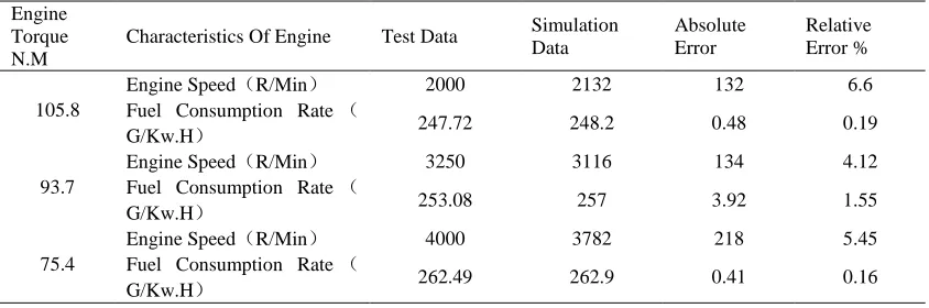
consumption are imported to build engine simulation numerical model and verify the feasibility and accuracy of the model of the engine. In the running simulation model, simulation time is set for 3s, and the throttle opening is 30%. Through the three data points of engine torque, 105.8Nm、
93.7 Nm and 85.4 Nm, the corresponding engine speed, fuel consumption, and the engine power are calculated, and the comparison of the data is shown in table1.
Table 1 Contrast Between Experimental Data And Simulation Data
Engine Torque N.M
Characteristics Of Engine Test Data Simulation Data
Absolute Error
Relative Error %
105.8
Engine Speed(R/Min) 2000 2132 132 6.6
Fuel Consumption Rate(
G/Kw.H) 247.72 248.2 0.48 0.19
93.7
Engine Speed(R/Min) 3250 3116 134 4.12
Fuel Consumption Rate(
G/Kw.H) 253.08 257 3.92 1.55
75.4
Engine Speed(R/Min) 4000 3782 218 5.45
Fuel Consumption Rate(
[image:4.612.96.518.593.733.2]Table 1 shows that the engine simulation model established can conform to the actual engine operation, and meet the needs of HILSS.
Clutch model. Clutch principle is shown in figure 5.
e
J Be ωe
e
T
cl
T Jp Bp ωp
l T cl
[image:5.612.92.297.141.241.2]F
Fig. 5 Schematic Drawing Of Clutch Combining Process
According to the chart above, dynamics equations of the driving and driven plates of the clutch can be obtained:
The driving plate:
e cl e e e e
T = T + J
ω
+ B
ω
(3)The driven plate:
cl l p p p p
T = T + J
+ B
η
ω
ω
(4)Where
ω
eandω
pare the angular velocities of thedriving and driven plates of the clutch,
e
B
andB
pare the equivalent damping coefficients,e
J
andJ
pare the moment of inertias,T
eis theengine output torque,
T
clis the torque passed by theclutch,
η
is automobile transmission efficiency,l
T
is the moment of resistance conversed from auto to the clutch output shaft.Among the parameters above,
T
lincludes; therolling resistance moment
T
f , air resistancemoment
T
w , ramp resistance momentT
i andacceleration moment of resistance
T
j , and theirrelationship is shown in the equation below:
2
2 0
cos sin ( )
21.15
l f w i j
w
w D a
a
t w
T T T T T
J
r C AV
Gf G m V
i i θ θ r
= + + + = + + + +
∑
(5)Where
G
is total vehicle weight,f
is rollingresistance coefficient (0.01~0.018),
θ
is ramp tiltangle,
C
Dis coefficient of air resistance (0.3~0.41),A
is frontal area,V
a is vehicle speed.Clutch model is built in Matlab/Simulink according to the above formulas. Run the module and calculate moment of resistance, clutch transmission torque and engine torque according to engine speed, transmission ratio and the road slope. The model is confirmed to meet the needs of HILSS by comparing calculated data to actual data.
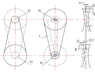
Speed ratio control model. In CVT, transmission ratio is controlled by changing the radius of driving and driven plates, and its principle is shown in figure 6:
2 1
i = R /R
(6)The speed ratio model formula can be written
like
i = f(S )
1 because the plate displacementsensor can detect the displacement of driving plate shaft S1, then the equation can be got:
R1 R1 R2 R2 L S1/2 S1 R m S2/2 S2 R n
Fig. 6 Structure Model Of Speed Ratio
1 1 1min 1 1 1 1 1 1 1 2
2 2 2
( ) ( ) 2 tan ( ) 4 2 S R R R R d i R d
R R d L
d d d R R
π π π
α − − + − − + + − = + = (7)
Where
R
1 is the driving plate pitch circle radius,1
[image:5.612.324.518.374.522.2]shaft,
L
is length of the metal strip,i
is transmission ratio.Speed ratio simulation model is built in Matlab/Simulink according to formula (7). Run the simulation model and get the corresponding transmission ratio
i
by inputting the axialdisplacement
S
1. In the current applied CVT, thedriving plate displacement ranges from 0mm to 16.1 mm, and the corresponding speed ratio ranges from 2.3788 to 0.4204, also the speed ratio of the
intermediate subtrahend gear and main subtrahend gear are 1.0545 and 1.184. So the CVT transmission ratio ranges from 2.97 to 0.5249. In
simulation model test,
i
max andi
min can beobtained by the input of the two limit points 0mm and 16.1mm of the driving plate. Comparison of the data is shown in table 2.
Table 2 shows that the speed ratio simulation module could conform to the actual CVT conditions, and meets the needs of simulation.
Table 2 Contrast Between Actual Speed Ratio And Simulation Speed Ratio
Plate displacement (mm) Actual i Simulation i Absolute error Relative error %
0 2.97 2.951 0.019 0.6397
[image:6.612.97.508.266.533.2]16.1 0.5249 0.573 0.0481 9.164
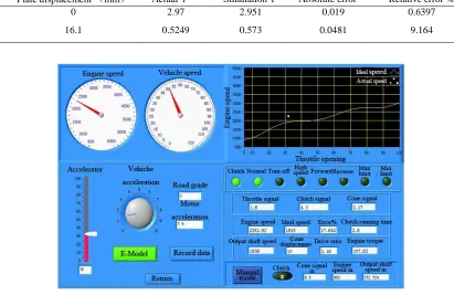
Fig. 7 Process Of Running HILSS Program
4. DEVELOPMENT AND DEBUGGING OF HILSS PLATFORM
According to the modular design of the main program’s calling subroutine, HILSS software platform presented in this paper can be divided into parameter setting module, signal generation and data acquisition module, engine module, clutch module, speed ratio module, ideal curve generating module with real-time speed generation module, load module, speed module and data recording module. The engine module, clutch module, the speed ratio module are established in accordance with previous described.
Simulation system is verified and debugged through tests. First, connect the power control box, then run the software, finally set the appropriate parameters for debugging. Automatic or manual mode can be chosen, and economic mode or dynamic mode can be switched. Running process of HILSS is shown in figure 7.
5. CONCLUSIONS
The construction and development of CVT HILSS are presented in this paper, and engine module, clutch module and speed ratio control module are established based on test data. Simulation test model is built in Matlab/Simulink based on the mathematical model, and is verified to be effective and reliable to satisfy HILSS. Furthermore, HILSS platform is set up and can be used to shorten the development cycle of CVT control system and reduce development costs.
The actual field tests have verified that this hardware in the loop simulation platform can meet the debugging needs of automotive continuously variable transmission control systems, and achieve the quantitative debugging purposes of bench tests and vehicle tests. Certainly, the vehicle’s actual operation is a very complex process, and many factors will change with the changes of operating conditions such as weather, speed, road conditions, etc. The simulation can only consider some important factors, and it is not enough. The engine model is built based on the engine test data. As the density of experimental data points is not enough, the intermediate state can only use interpolation method to obtain. Therefore, the model has some differences with the actual state of the engine operation, and the simulation models use steady-state models which are different with the dynamic models of actual operation.
ACKNOWLEDGMENTS
This project was supported by the science and technology key project of Liaoning province, P.R. China (No. 2009220015).
REFRENCES:
[1] Lei Zhang, Tao Wei and Guoning Li, “The Hardware in the Loop Simulation System of Speed Ratio Control on EMCVT”, Advanced Materials Research, , Vol.219-220,, 2011, pp. 1675-1678.
[2] Yuanchun Cai and Yunshan Zhou, “Research of CVT experimental system based on HILSS”, Journal of Scientific Instrument, Vol.30, No. 5, 2009, pp. 960-965.
[3] Shize Ma and Yucheng Lei, “A Three-Level Advanced Static VAR Compensator”, Research of metal belt CVT speed ratio control, Vol. 31, No.2, 2003, pp.210-211.
[4] Ying An, Chuanxue Song and Shuai Gao,
“Metal belt continuously variable transmission hardware in the loop simulation system”. Journal of Agricultural Machinery, Vol.42, No.11, 2011, pp.60-63.
[5] Naishi Cheng, etc., “Automotive metal belt CVT- Principle and design of CVT”. Beijing: Machinery Industry Press. 2007.
[6] P. K. De and Amita Bhincher, “Dynamic Programming and Multi Objective Linear Programming approaches”. Appl. Math. Inf. Sci. Vol.5, No.2, 2011, pp.253-263.
[7] Lei Zhang, Yan Chen, Xiumin Yang, Chun-yang Zhou and Wenjia Zhang, “Research on the Characteristic Description and the Numerical Model of 4G15-6L Automotive Engine”, Applied Mechanics and Materials, Vol.201-202, 2012, pp.127-130.
[8] Lei Zhang, Yanchun Zai, Haixin Zhao and Guanjin Chen, “Research on Control Strategy and Experiment of Electronic Mechanical Continuously Variable Transmission”, Applied Mechanics and Materials, Vol.88-89, 2011, pp.191-196.
[9] Lei Zhang, Xiaoming Zhang, Xiumin Yang and Yan Liu, “The Study on Fuzzy Control of Automotive Clutch”, Advanced Materials Research, Vol.230-232, 2011, pp.334-338. [10] Lei Zhang, Tao Wei and Guoning Li, “The