Analysis and Synthesis of Elevator Controller Based On
VHSIC Hardware Description Language
Ei Phyu Soe*, Dr.Myint Myint Soe**, Htet Htet Yi***
*Department of Electrical Systems and Instrumentation, Myanmar Aerospace Engineering University
**Department of Avionics, Myanmar Aerospace Engineering University
***Department of Avionics, Myanmar Aerospace Engineering University
DOI: 10.29322/IJSRP.9.04.2019.p8806
http://dx.doi.org/10.29322/IJSRP.9.04.2019.p8806
Abstract- This paper presents a simple design and implementation of an elevator controller based on Very High-Speed Integrated Circuits Description Language (VHDL). The controller is implemented in a FPGA using Altera Quartus II software package verision 9.0 (Web Edition). The Altera Quartus II software package is an integrated development environment (IDE) supplied by Altera for the creation of HDL applications. This controller can be implemented for an elevator with the required number of floors by simply changing a control variable in the VHDL code. In the proposed design a VHDL code is developed to control the lift moment based on the request it will get. The design is based on the synchronous input which should be operating with a fixed sort of frequency. Finally the RTL(register transfer level) is verified and implemented in Precision Synthesis Tool. In this paper, the five-floor controller will be modelled with VHDL code using QII software.
Index Terms-VHDL, Quartus II, IDE, simulation, controller. I.INTRODUCTION
An elevator system is a vertical transport vehicle that efficiently moves people or goods between floors of a building.It can be considered as a complex reactive system which requires parallel event processing with large number of inputs and outputs.
Floor Number
Display
Call Pulse Request Pulse
Floor Sensor
FLRCall
FLRREQ
Up Down Stop/
Open
Close
[image:1.612.321.578.438.735.2]Controller
Floor Counter
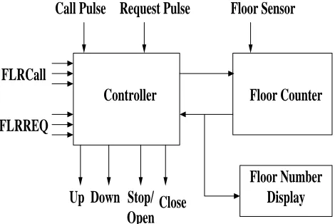
Fig. 1 Block Diagram of Elevator Controller
Fig.1 shows the elevator block diagram, which consists of controller logic, floor counter, and a floor number display. The controller consists of logic that controls the elevator operation, a counter that determines the floor at which the elevator is located at any given time, and a floor number display. For simplicity, there is only one floor call and one floor request for each elevator cycle. A cycle occurs when the elevator is called to a given floor to pick up a passenger and the passenger is delivered to a requested floor. The elevator sequence for one cycle is shown in fig. 2.
[image:1.612.48.283.543.700.2]CALL/REQ code register and a CALL pulse is generated to enter the code into the register. The same process occurs when a request button is pressed inside the elevator. The code is input to the CALL/REQ code register, and a REQ pulse is generated to store the code in the register. The elevator does not know the difference between a call and a request. The comparator determines if the destination floor number is greater than, less than, or equal to the current floor where the elevator is located. As a result of this comparison, either an UP command, a DOWN command is issued to the elevator motor control. As the elevator moves toward the desired floor, the floor counter is either incremented at each floor as it goes up or decremented at each floor as it goes down. Once the elevator reaches the desired floor, a STOP/OPEN command is issued to the elevator motor control and to the door control. After a preset time, the delay timer issues a CLOSE signal to the elevator door control. As mentioned, this elevator design is limited to one floor call and one floor request per cycle.
III. IMPLEMENTATION OF ELEVATOR CONTROLLER
We can use the Quartus II Block Editor, Text Editor, MegaWizard Plug-In Manager, and EDA design entry tools to create the design files in a project. We can create schematic or block designs with the Block Editor, or we can create AHDL, VHDL, or Verilog HDL designs with the Text Editor. In application of software can also create Block Design Files that contain blocks and symbols that represent logic in the design. The Block Editor incorporates the design logic represented by each block diagram, schematic, or symbol into the project. We can create new design files from the blocks in a Block Design File, update the design files when we want to modify the blocks and the symbols, and generate Block Symbol Files (.bsf), AHDL Include Files (.inc), and HDL files from Block Design Files. And then it can also analyze the Block Design Files for errors before compilation. In our project used the text entry and then create the block symbol.
VHDL is a Hardware Description language. It describes the behavior of an electronic circuit or system, from which the physical circuit or system can be attained (implemented). VHDL is intended for circuit synthesis as well as circuit simulation. A typical VHDL description includes a port contained within an entity statement. The purpose of this paper to practice implementation VHDL codes and performing simulations on various digital logic designs. All the modules described in this section are coded using VHDL which is very useful tool with its degree of concurrency to cope with the parallelism of digital hardware. The top level of module connects all the stages into a higher level at Register Transfer Logic (RTL).
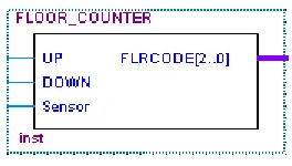
Fig. 3 Top Level of Floor Counter
The floor counter sequentially tracks the number of the floor and always contains the number of the current floor. It can count up or down and can reverse its state at any point under the direction of the state controller and the floor sensor input.
[image:2.612.380.512.79.154.2]B. Floor Comparator
Fig. 4 Top Level Comparator
This block symbol describes the requirements of inputs and outputs in terms of digital logic to execute the desired operations. The declared inputs FlrCodeCall, FlrCodeCnt are std_logic_vector data types and the inputs/outputs UP, DOWN, and STOP are std_logic.This circuit compares the current floor and requested floor and then give the output to move the elevator.
[image:2.612.375.513.265.366.2]C. Code Registser
Fig. 5 Top Level of Code Register
Code register stores the floor call code and floor call request. Clock event high pulse sends the FlrCodeIn floor number to FlrCodeOut.
[image:2.612.318.525.497.612.2]fig. 6 Top level of Timer
In timer code consists of enable, clock, and setCnt inputs. setCnt limits to 1023 for ten bits. Counter output declares as qOut.
[image:3.612.111.221.59.141.2]E. Flip-flop
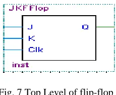
Fig. 7 Top Level of flip-flop
The flip-flop is a JK flip-flop. It gets the clock from timer output. Its output Q goes to code register as clock input.
F. Seven-segment Decoder
Fig.8 Top Level of Seven-segment decoder
Seven-Segment decoder receives the input from the output of floor comparator and decodes to display as floor number.
G. Elevator Controller
[image:3.612.112.227.230.324.2]In VHDL, there are three types of modeling design: the data flow level, behavioral level, and structural level. In our project we use the behavioral modeling in each design logic components. And then we create the complete VHDL program code for the elevator controller using the previously defined components by structural modeling method as follows (see fig. 9).
Fig.9 Top Level of Elevator Controller
After compiling the project we got the following compilation report which includes the analysis and synthesis modules. If the report provides the syntax errors and schematic error , and we can change the input design file.
Fig.10 Compilation result for Controller
IV. SIMULATION RESULT ON QII SOFTWARE A. RTL and Technology Map View
The VHDL coding of this paper design is compiled and simulated using Quartus II version 9.0. The Quartus II development software provides a complete design environment for system-on-a-programmable-chip (SOPC) design. This software not only compiles the given VHDL code but also produces waveform results and Register Transfer Logic (RTL). The RTL Viewer, State Machine Viewer, and Technology Map Viewer allow to view schematic representations of the internal structure of our designs. Each viewer displays a unique view of the netlist, and allows to view different internal structures.
[image:3.612.315.585.315.531.2] [image:3.612.121.222.380.520.2]optimizations:
• Removes internally used tri-state buses.
• Connects bidirectional pins directly to their sources. • Removes single input nodes.
• Converts NOT gates to bubble inversions. • Removes registers without fan-in or fan-out.
• Merges chains of equivalent combinational gates into a single gate.
Fig.11 RTL level of Elevator Controller
Fig.12 Post Mapping of Elevator Controller
The RTL Viewer and Technology Map Viewer provide a hierarchy list that displays a representation of the project
• All encrypted design and I/O pins instances appear gray. • All state machine nodes appear yellow (RTL Viewer
only).
• All logic cells and I/O cells for which you can view the underlying internal implementation appear blue (Technology Map Viewer only).
• All RAM blocks and DSP blocks appear blue. • All other design instances appear light green.
B .Functional Simulation
In order to simulate the elevator controller design, first open the vector waveform file. The Quartus II Simulator is a tool for testing and debugging the logical operation and internal timing of our design.Graphical waveforms are created to provide the input stimulus to test the elevator controller application. Inputs Call, Request, CallCode, PanelCode, Sensor, and Clk will be created using graphical tools. Output identifiers UP, DOWN, STOPOPEN, CLOSE, and seven-segment outputs ‘a’ through ‘g’ require no input stimulus. The timing diagram is developed using software for the proposed system. We set up the inputs data to the file and then saved the file as .vwf. Before starting a simulation, we must generate the appropriate simulation netlist by either compiling the design for timing simulation, or using the Generate Functional Simulation Netlist command for functional simulation.
Fig.14 Set up inputs data to the file
Clk J K Q 1 1 Clk
FlrCodeIn[2..0] FlrCodeOut[2..0] FlrCodeCall[2..0] FlrCodeCnt[2..0] DOWN STOP UP DOWN Sensor UP FLRCODE[2..0] H0 H1 H2 a b c d e f g clk enable setCnt[9..0] qOut BUF (DIRECT) BUF (DIRECT)
BUF (DIRECT) BUF (DIRECT) BUF (DIRECT) BUF (DIRECT) BUF (DIRECT) BUF (DIRECT) BUF (DIRECT) BUF (DIRECT) SEL DATAA DATAB OUT0 MUX21 JKFFlop:CALLREQ CODE_REg:CODEREG FLRCALL_COMP:FLCLCOMP comb~0 comb~1 comb~2 comb~3 comb~4 comb~5 comb~7 comb~8 comb~9 comb~11 comb~12 FRIN[2..0] Call Request Sensor Clk UP DOWN STOPOPEN CLOSE a b c d e f g CallCode[2..0] PanelCode[2..0] Seg_1:DISPLAY comb~6 FLOOR_COUNTER:FLRCNT Timer:TIMER1
10' h00A
--comb~10
Clk flrcall comp:FLCLCOMP:Equal0~1 qOut~reg0
Fig.13 Nestlist file
Fig.15 Simulator Report
In the simulation result, we can see the inputs and outputs by vector waveform file. We set the call code (1), panel code (1 to 7), the clk, call, sensor input and request. After the simulation, We found the output identifiers up, down, stopopen, close, and seven-segment
Fig.16 Simulation Result of Controller
V. CONCLUSION
In this paper, the analysis and synthesis processes of elevator controller was implemented using VHDL code , generating RTL review, verifying the vector waveform by QII software. These processes can be easily to modify the elevator controller program for building with the required floors rather than five. And so the QuartusII software makes it easy to implement a desired logic circuit by using a programmable logic device, such as a field-programmable gate array (FPGA) chip such as Development and Education Board (DE1).
REFERENCES
[1] Thomas L.Floyd. Digital Fundamentals, Eleventh Edition, Pearson Education Limited, 2015.
[2] Altera, DE1 Development and Education Board User Manual, Altera Corporation, 2012.
[3] Ronald J.Tocci, Neals S.Widmer, and Gregory L.Moss, Digital System Principles and Applications, Tenth Edition , Pearson International Education,2007.
[4] Fadhli Shahir Bin Zakaria. Design and Implementation of Elevator Controller on a FPGA, Faculty of Electronic and Computer Engineering University Technical Malaysia Melaka,2012.
[5] Volnei A.Pedroni, Circuit Design with VHDL, Massachusetts Institute of Technology, 2004
[6] Shikha Khurana, Kanika Kaur, Implementation of ALU using FPGA,KIIT Gurgaon, India, 2012.
[7] Abdulrahman A.AEmhemed, Implementation 7segment Display by Educational Board Software/Hardware Interfacing, College of Electronic Technology-Bani Walid, Libya, 2012.
[8] https://www.altera.com.
AUTHORS