A SIMPLIFIED CONTROL STRATEGY FOR DC MICRO GRID CONSISTS
OF MULTIPLE DISTRIBUTED GENERATION SOURCES
T. Narasimha Prasad
1and A. Lakshmi Devi
21
PVP Siddhartha Institute of Technology, Kanuru, Vijayawada, India
2Department of Electrical Engineering, SVU College of Engineering, Sri Venkateswara University, Tirupati, Andhra Pradesh, India
E-Mail: [email protected]
ABSTRACT
The conventional energy sources are not able to meet the increasing load demand, because those are depleting day by day. Therefore, the research has been done in this regard and resulting in introduction of renewable energy sources. These renewable energy sources became more popular because of its advantages like free of cost and pollution free. The solar energy, fuel cell and wind energy is being used frequently for power generation. Despite of its advantages it gives very less output voltage and further we need to increase the voltage level. Hence it is necessary to use voltage conversion device like DC-DC converter. In general, the current control technique is used to control the converters. In this paper, two renewable energy sources are considered and connected in parallel. Along with the conventional current control technique a voltage follower current control technique is proposed and implemented. The circuits are analyzed using Matlab/simulink software.
Keywords: renewable energy sources, distributed generation, dc-dc converters, current control technique, voltage follower current
control technique.
INTRODUCTION
The utilization of electrical equipment is being increased for the last decade in both industries and domestic applications. To meet this increased load demand, the existing conventional energy sources are not sufficient because, the conventional energy sources are diminishing continuously. Therefore, the research has been started for alternative energy sources and the outcome is renewable energy sources (RES) [1-3] like solar, wind and fuel cell. These sources are continuously available in the nature. Moreover, in case of conventional energy source the produced power must be transmitted to the load centers using transmission line. This transmission includes more cost and losses. In case of renewable energy source, the power generation can be done at load centers itself by which we can reduce the transmission line cost and transmission losses. This process of producing power at load centers is known as distributed generation (DG) [4-6].
The distributed generating systems also called as embedded generating system or dispersed generating system. The DG system ranges between few kilo watts to 100 mega watts. Distributed generation technology has less impact on environment when compared to conventional fossil fuel generation. This is extremely true for photo voltaic system and fuel cell system. The output voltage of these units is DC and very low value. To integrate these DG systems to the grid or to connect to the load this low voltage must be increased to desired level. This voltage step up is done by using DC-DC converters [7-9]. In general the conventional boost converter is used for this purpose.
However, the closed loop control of DC-DC converter [10-11] is essential for required output. The general method for controlling the boost converter is conventional current control method. In this method, the output current of boost converter is sensed and compared
with the desired reference value. The gating pulses are generated according to error value. In this paper, along with the conventional current control method a voltage follower current controller (VFCC) is proposed to maintain the currents as well as voltage at desired value. VFCC maintains the load voltage as desired value by maintaining the required currents. The circuits are analyzed using Matlab/simulink software. The results are displayed for both the control methods by applying different conditions.
RENEWABLE ENERGY SOURCES CONNECTED IN PARALLEL PV System DC-DC Boost Converter Fuel Cell DC-DC Boost Converter RLoad
Figure-1. Parallel connected renewable energy sources.
Figure-1 shows the two renewable energy sources connected in parallel feeding the resistive load. The output of RES system is connected to DC-DC boost converter because; output voltage of PV system and fuel cell is very low. And this low voltage has to step up for desired value. A conventional DC-DC boost converter has been used for this purpose.
CURRENT CONTROL TECHNIQUE PV system <= Relational Operator Gating Pulses Repeating Sequence Gain 1/S Gain Integrator Iactual Ireference Saturation K K + ++ -Fuel cell <= Relational Operator Gating Pulses Repeating Sequence Gain 1/S Gain Integrator Iactual Ireference Saturation K K + ++ -L D
S C R
L D
C S
Figure-2. Current control technique.
VOLTAGE FOLLOWER CURRENT CONTROL TECHNIQUE
PV system <= Relational Operator Gating Pulses Repeating Sequence Gain 1/S Gain Integrator Iactual Saturation K K + ++ -L D
S C R
Ireference Gain 1/2 + Gain K + -K 1/S Integrator Gain Vdc(reference) Vdc(actual) PV system <= Relational Operator Gating Pulses Repeating Sequence Gain 1/S Gain Integrator Iactual Saturation K K + ++ -L D S C Ireference +
-Figure-3. Voltage follower current control technique.
Figure-2 shows the current control technique for the boost converters operating in parallel. Each boost converter has its own current control circuit. In this the actual current flowing from the boost converter is sensed
form for generating gating pulse for the switch. With this current control technique the boost converter will send desired value of current as per requirement.
The boost Figure-3 shows the proposed voltage follower current control technique. In this control, the current from converters will be required value while maintaining the voltage at load as desired value. The voltage at load terminal is sensed and compare with the reference voltage. The error voltage is given to the PI controller which gives the proportionate current signal. This current signal is divided in to two equal parts and subtracted from the reference currents of individual converters.
SIMULATION RESULTS
Table-1. Simulation parameters.
Parameter Value
Input Voltage 100 Volts
Boost Inductor 0.33 mH
DC Link Capacitor 116 µF
Output Resistance 6.1403 Ω
a) Current control technique
Case1: Equal current sharing
Figure-4. Output voltage of boost converter 1.
Figure-5. Output current of boost converter 1.
Figure-6. Output voltage of boost converter 2.
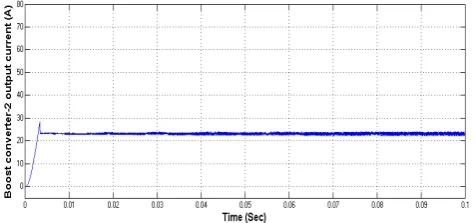
Figure-7. Output current of boost converter 2.
Case2: Unequal current sharing 1
Figure-8. Output voltage of boost converter 1.
Figure-9. Output current of boost converter 1.
Figure-10. Output voltage of boost converter 2.
Figure-11. Output current of boost converter 2.
The output voltages of converter 1 and 2 are shown in Figures 8 and 10 respectively. In this case, the current shared by the both converters are not same. The converter 1 shares the current of 23 amps and converter 2 shares the current of 34 amps.
Case3: Unequal current sharing 2
Figure-12. Output voltage of converter 1.
Figure-13. Output current of converter 1.
Figure-14. Output voltage of converter 2.
Figure-15. Output current of converter 2.
b) Voltage follower current control technique Case1: Equal current sharing
Figure-16. Output voltage of boost converter 1.
Figure-17. Output current of boost converter 1.
Figure-18. Output voltage of boost converter 2.
Figure-19. Output current of boost converter 2.
In voltage follower current control technique, the current of individual converters can be controlled while maintaining the required value of load voltage. We could observe clearly that, the output voltage of each converter is maintained at 350volts and currents are shared by equally with a magnitude of 28.5 amps. The wave forms of voltage are shown in Figures 16 and 18 respectively and
the current wave forms are shown in Figures 17 and 19 for the converters 1 and 2 respectively.
Case2: Unequal current sharing 1
Figure-20. Output voltage of boost converter 1.
Figure-21. Output current of boost converter 1.
Figure-20 shows the output voltage of boost converter 1 which is maintained at 350 volts while the current shared by it is 23 amps as shown in Figure-21.
Figure-22. Output voltage of boost converter 2.
The output voltage of boost converter 2 is shown in Figure-22 and the magnitude is 350 volts but the current shared by it is 34 amps.
[image:6.595.52.289.156.277.2]Case 3: Unequal current sharing 2
[image:6.595.52.289.304.417.2]Figure-24. Output voltage of boost converter 1.
[image:6.595.53.290.448.553.2]Figure-25. Output current of boost converter 1.
Figure-26. Output voltage of boost converter 2.
Figure-27. Output current of boost converter 2.
In this case, the current shared by the converter 1 is 34 amps and the current shared by the converter 2 is 23 amps. But the voltage is maintained constant at required value 350 volts. The voltage waveforms are shown in
figure 24 and 26 for converters 1and 2 respectively and the current waveforms are shown in the Figures 25 and 27 for converters 1 and 2 respectively.
CONCLUSIONS
In conclusion, it is strongly recommended that the voltage follower current control technique is best suitable for controlling the parallel operating boost converters. In this paper, the analysis for parallel operating boost converters is done using current control technique and voltage follower current control technique. Different cases have been applied like equal current sharing and unequal current sharing. Again in unequal current sharing the current values are exchanged and applied. In all these cases the current control technique worked out but it could not able to maintain the required voltage at output. However, using voltage follower current control technique, the preset currents are flowing from the converters while maintaining the load voltage constant. The circuits are simulated in Matlab/simulink software and results have been displayed.
REFERENCES
[1] V. Elistratov, M. Konischev and M. Fedorov. 2017. Optimization of power supply of the circumpolar territories on the basis of renewable energy sources. 2017 International Conference on Industrial Engineering, Applications and Manufacturing (ICIEAM), Saint Petersburg, Russia, 2017, pp. 1-5
[2] J. Tompkins, M. Musiak and N. Magotra. 2017. Design of a low cost DC/AC inverter for integration of renewable energy sources into the smart grid. 2017 IEEE 60th International Midwest Symposium on Circuits and Systems (MWSCAS), Boston, MA. pp. 487-490
[3] Huang Yinuo, Guo Chuangxin, Wang Licheng et al. 2015. A cluster-based dispatch strategy for electric vehicles considering user satisfaction [J]. Automation of Eletric Power Systems. 39(17): 183-191.
[4] T. M. Masaud, C. O. E. Ukah, R. Deepak Mistry and R. Challoo. 2017. Placement and sizing of parallel reactive power compensation in the presence of distributed generation for line loss reduction. 2017 IEEE Power & Energy Society Innovative Smart Grid Technologies Conference (ISGT), Washington, DC, USA. pp. 1-5.
[image:6.595.52.290.586.697.2]Manufacturing (ICIEAM), Saint Petersburg, Russia. pp. 1-4.
[6] B. R. Pereira, G. R. M. da Costa, J. Contreras and J. R. S. Mantovani. 2016. Optimal Distributed Generation and Reactive Power Allocation in Electrical Distribution Systems. in IEEE Transactions on Sustainable Energy. 7(3): 975-984.
[7] R. Maurya, S. R. Arya and A. P. Raj. 2016. Experimental evaluation of interleaved DC-DC converters for maximum PV power tracking. 2016 IEEE 7th Power India International Conference (PIICON), Bikaner, Rajasthan, India, 2016, pp. 1-6.
[8] B. Kunalkumar, R. A. Gupta and N. Gupta. 2017. A comparative analysis between three stage and two stage bidirectional dc-dc converter in battery storage application. 2017 International Conference on Power and Embedded Drive Control (ICPEDC), Chennai, India. pp. 312-317.
[9] Y. Yang, J. Ma, C. N. M. Ho and Y. Zou. 2015. A New Coupled-Inductor Structure for Interleaving Bidirectional DC-DC Converters. in IEEE Journal of Emerging and Selected Topics in Power Electronics. 3(3): 841-849.
[10]L. K. Uttarala, J. V. Rao, K. K. Vanukuru and B. A. Kiran. 2016. RES FED high gain DC-DC converter with closed loop control for induction motor drive. 2016 International Conference on Signal Processing, Communication, Power and Embedded System (SCOPES), Paralakhemundi. pp. 1404-1409.