Fuzzy Based Trajectory Tracking Control of a Mobile
Robot
Me Me Ko
*, Kyaw Thiha
**, Theingi
***
Department of Mechatronic Engineering, Mandalay Technological University, Myanmar
**
Technological University (Thanlyin), Myanmar
1
[email protected],
2[email protected],
3[email protected]
DOI: 10.29322/IJSRP.8.12.2018.p8489http://dx.doi.org/10.29322/IJSRP.8.12.2018.p8489
Abstract- In this research, a differential drive wheeled mobile robot which can automatically track the trajectories was designed by using the fuzzy logic controller. The motion task of the mobile robot is motion through the points. When the user gives the desired point’s position (x, y, θ) from PC, the position error and orientation error are derived. The position error and orientation error is sent as input to the fuzzy controller and then the required velocity is given to the motor depending to the position and orientation angle between the start point and desired point. Based on the electrical section, PIC16F887 microcontroller, motor driver, magnetic encoder DC motor and LCD are mainly used. The purpose of the use of driver is to control the rotation of the motors - forward or backward. So, VNH2SP30 driver is used in this system for this purpose. The magnetic encoder is to measure wheel revolution and it can b e translated into linear displacement of the wheel. The design procedure consists of the kinematic structure of robot, hardware and software implementation and microcontroller programming. A simulation model of the control system is developed with MATLAB / SIMULINK block diagram. Simulation results of the proposed system are given to approve the effectiveness of the system.
Index Terms- Trajectory Track, Fuzzy Logic Controller,PIC16F887 Microcontroller, DC Motor I. INTRODUCTION
In the last decade, the main developments in the area of robotics have come through technological breakthroughs in the areas of computing telecommunications, software, and electronic devices. These technologies have facilitated improvements in intelligent sensors, actuators, and planning and decision making units which have significantly increased the capabilities of mobile robots. The latest trend in robotic intelligence is toward imitating life, for instance in evolutionary robots and emotional control robots. Another area of technological challenge for the next decade is the development of micro-robots and nano-robots for medical applications. In order to drive the most suitable feedback controllers for each control system, it is convenient to classify the possible motion tasks: Point-to-point motion, Path following and Trajectory tracking.
An autonomous mobile robot is an intelligent robot that performs a given work with sensors by identifying the surrounded environment and reacts to the condition by itself instead of human. Many studies about autonomous navigation applied to non-holonomic robots focused on the design of a global analytic trajectory, composed of straight segments connected with either tangential circular or symmetric arcs [1]. In the trajectory tracking control, the desired trajectory required by mobile robot is given in graph based on the time relation.
In trajectory tracking control, the desired trajectory required by mobile robot is given in graph based on time relation. Trajectory tracking control is necessary when the robot is asked to arrive at a certain location in a certain time. Various methods have been applied to solve the motion control problems. The various methods are model –based methods and artificial methods those employ fuzzy logic, neural networks, genetic algorithms or hybrid of these approaches. Among these methods, fuzzy logic controller is used to control the various paths and the system maintains a good tracking performance.
Although these methods have been proven to be efficient and provide good short term position estimates, they suffer from unbounded error growth due to the integration of minute measurements to obtain the final estimate [2]. In fact, there is a high demand for mobile robots to use in hard to reach and hazardous areas [3]. This approach involves two steps: first planning a feasible trajectory and second designing a control algorithm to follow this trajectory [4]. This method has a drawback the lack of reactivity. For more reactive navigation, kinematic constraints have been introduced in the spatial representation [5].
II. TRAJECTORY TRACKING OF MOBILE ROBOTMETHODOLOGY
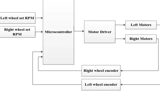
The trajectory tracking of mobile robot system is constructed with switch, motor driver, microcontroller, 12V battery and DC gear motors. Fig.1 shows the block diagram of motor control for mobile robot trajectory tracking control.
Right wheel set
RPM Microcontroller Motor Driver
Left Motors
Right Motors Left wheel set RPM
[image:2.612.169.440.101.255.2]Left wheel encoder Right wheel encoder
Figure 1: Block diagram of motor control for mobile robot
The coordinates of the vehicle is q = (x, y, θ), and (x, y) are the position of the wheels (m), and θ is the orientation (heading) of the wheels (rad). The kinematics models of the mobile robot equation are based on the unicycle equation.
ẋ = V cos θ (1) ẏ = V sin θ (2)
θ̇ = ω (3)
Where, V is the linear velocity (m/sec) and ω is angular velocity (rad/sec). The following equations are used to find the linear velocity and angular velocities.
V =vl + vr
2 (4)
ω = vl − vr D (5)
Left and right wheel linear velocities (m/sec) are shown in the following;
vr
=
(6)vl
=
Where, r is radius of the wheels,𝑣𝑟and 𝑣𝑙are right and left wheel linear velocities, R is the radius of the wheels and the distance
between the wheels is D. Error position and orientation can be estimated as follow:
E𝑝= √(x𝑔− x )2 + ( y𝑔 − y)2(7)
θg = θgoal = arctan2 ( y𝑔 − y
x𝑔 − x ) (8)
Error orientation, 𝑒 = θ𝑔 – θ
Corrected error, Eθ= arctan2 (sin (e), cos (e))
The kinematic model equation of the mobile robot is given by:
q = ( ẋ ẏ θ̇
) = (
cos θ 0 sin θ 0
0 1
) (ωv) (9)
A. Hardware Components of Mobile Robot
The components of mobile robot are two DC gear motor with encoder, one caster wheel,VNH2SP30 motor driver, 12V battery and PIC16F887 microcontroller. DC gear motor reduction ratio is 1:45 gearbox and revolution is 12 pulses per revolution of the motor
shaft. Motor driver can control the motors to drive the mobile robot as defined trajectory. In this research, RB0 and RB1 pins of PIC16F887 were used for right motors to rotate forward and track the trajectory. RB2 and RB3 pins were used for left motors. For pulse width modulation (PWM), RC1 and RC2 pins were used to control the motors.Fig. 2 shows the implementation of mobile robot.
Figure 2: Mobile Robot
B. Communicating with MATLAB Simulink and hardware controller
The set rpm values from workspaceare taken and put them into the controller of mobile robot. Controller evaluates the PWM duty cycle % with motor driver circuit. “To instrument” block is used for transferring the left and right duty cycles to the mobile robot. The communication of PIC and MATLAB is serial interface and its buffer size is 512 and baud rate is 115200. The block sample rate is 0.001sec. The travelling record of the mobile robot data is expressed on “Query instrument” block. Its buffer size and baud rate is similar with “To instrument” block.
III. FUZZYLOGICCONTROLLER
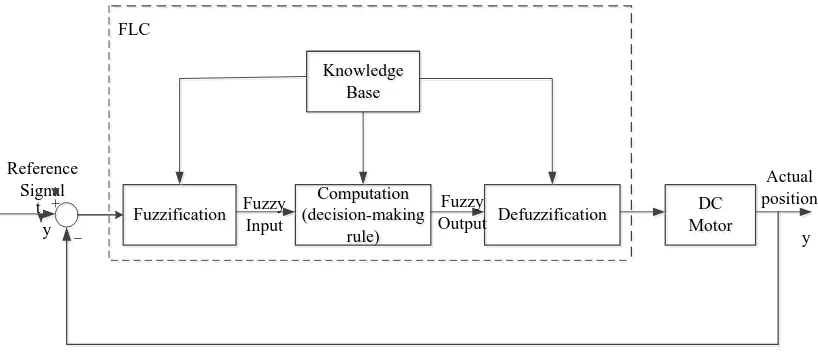
The basic fuzzy logic controller (FLC) structure is shown in Fig.3, where FLC is used a supplementary role to enhance the existing control system when the control conditions change. Fuzzy control algorithm is demonstrated for tracking trajectories. The calculation module calculates the error in position and orientation Δx, Δy, Δθ between the actual robot coordinates (x, y,) and the coordinates of the trajectory (xd, yd, θd) at each sample time. After that, the position and angle is generated to be the inputs of Fuzzy controller. To control the system, we assume the two state variables to be 0 ≤ v (position) ≤ 1 (m/s); -pi ≤ θ (angle) ≤ pi (rad).
Computation (decision-making rule) Computation (decision-making rule) Defuzzification Defuzzification DC Motor DC Motor Fuzzification Fuzzification Knowledge Base Knowledge Base FLC Fuzzy Input Fuzzy Output Reference Signal t y + _ Actual position y
Figure 3: Basic structure of fuzzy logic controller
The knowledge base contains a set of rules which construct the decision-making logic rule table tabulated where 25 rules are used. The label and number of rules can be changed according to project preference. An addition of input and output sets can provide much more accurate results but longer time is needed to run the Simulink.
A. Constructing Membership Function
[image:3.612.108.517.432.614.2]inputs and outputs are shown in Fig. 4, where 0 ≤ Ep (error position) ≤ 1.5 (m); -pi ≤ Eo (error orientation) ≤ pi (deg); 0 ≤ v (position)
≤ 1 (m/s); -2 ≤ w (position) ≤ 2 (rad/s).
(a) Membership function of input variable Ep (b) Membership function of output variable v
[image:4.612.189.424.554.727.2](c) Membership function of input variable Eo(d) Membership function of output variable w
Figure 4: Membership functions
B. Fuzzification and Rule Base
The first block inside the controller is fuzzification which converts each piece of input data to degrees of membership by a lookup in one or several membership function. The fuzzification block matches the input data with the conditions of the rules to determine.
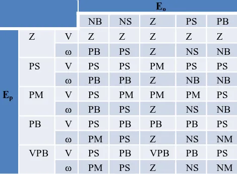
In order to satisfy the control objective it is necessary to design a fuzzy logic control for the real velocities of the mobile robot which use linguistic variables in the inputs and outputs. After constructing the stage of membership functions, the table for the rule bases is constructed.The expert system is developed based on the IF- THEN rules as 25 rules to control robot tracking defined trajectory.
If Ep is Z and Eo is NB, Then V is Z and ω is PB. This rules quantifies the position and orientation where the predicted the position
and angle of the mobile robot is much larger than the reference position and angle. Therefore, we must decrease V and ω to reduce the position and orientation of robot.
When Ep and Eo are not Z, we design the fuzzy rules as below: If Ep is PS and Eo is NB, Then V is PS and ω is PB.
If Ep is PM and Eo is NB, Then V is PS and ω is PB. If Ep is PB and Eo is NS, Then V is PB and ω is PS. If Ep is VPB and Eo is PS, Then V is PB and ω is NS.
The fuzzy rules bases for the mobile robot control are described in Table 1.
Table1. Fuzzy rules for the mobile robot control
Eo
NB NS Z PS PB
Ep
Z V Z Z Z Z Z
ω PB PS Z NS NB
PS V PS PS PM PS PS
ω PB PB Z NB NB
PM V PS PM PM PM PS
ω PB PS Z NS NB
PB V PS PB PB PB PS
ω PM PS Z NS NM
VPB V PS PB VPB PB PS
C. Defuzzification
Considering the real-time characteristics and the complexity of the algorithm, the centroid method is used to defuzzify the output variable. At first, the rule for output which best fits the current situation is chosen. In other words, more certainly that these rules can be applied than the other rules. Then, the output value that has the maximum membership function value is found according to these rules. If there is more than one variable that has the same maximum membership function value, the average of this variable is produced.
IV. DESIGN OF TRAJECTORY TRACKING MOBILE ROBOT
[image:5.612.49.563.247.492.2]The following Simulation block diagrams are designed for the trajectory tracking of mobile robot. Fig.5 shows the Simulink block diagram of the various trajectories tracking control system. Simulink block diagram of unicycle is shown in Fig.6.In this system, x, y, and θ are calculated based on the linear velocity and angular velocity. And then, left and right set rpm of velocities and duty cycles are evaluated.
Figure 6: Simulink block diagram of unicycle
V. EXPERIMENTALRESULTS
A. Simulation Results
For testing the performance of the operation, the following MATLAB simulation was applied. Fig.7 shows the desired and actual square trajectory tracking of mobile robot. There were a few errors in square trajectory. The mobile robot tracked the outer route of every corner for square trajectory. Error position and orientation of square trajectory is shown in Fig.8.
[image:6.612.196.416.380.524.2]Figure 8: Error position and orientation of square trajectory
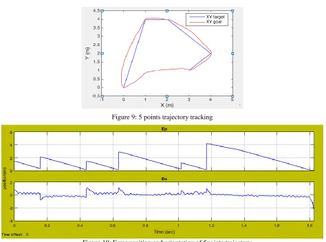
The desired and actual 5 points trajectory tracking of mobile robot is shown in Fig.9. Error position and orientation of 5 points trajectory is shown in Fig.10.
[image:7.612.70.544.289.641.2]Figure 9: 5 points trajectory tracking
Figure 10: Error position and orientation of 5points trajectory
B. Hardware Experiment Results
Figure 11: Testing x=2m, y=2m squaretrajectory tracking
Figure 12: Testing 5 pointstrajectory tracking
VI. CONCLUSION
The distance travelled by the robot was calculated by transforming the number of wheel revolution counted using a magnetic encoder knowing the diameter of the wheel. The position error and angle orientation error in the command speed of the mobile robot, output from the microcontroller, is changed into analog signal fed to the motor driving of the corresponding wheel to fix the position error.The strategy presents a desired performance as it is able to accurately follow the different designed trajectory which makes it desired for the case of working in indoor environment. The simulation results are provided to illustrate the feasibility and effectively of the proposed fuzzy logic controller. It was applied on simulation scheme in purpose to track target trajectory. The results of simulations present that proposed method is suitable to solve the problem of target tracking.
ACKNOWLEDGMENT
Firstly, I would like to acknowledge particular thanks to Dr. Sint Soe, Rector of Mandalay Technological University (MTU), for his kind permission to carry out this research. I would like to thank Dr. Wutyi Win (Professor and Head) and my supervisor, Dr.Kyaw Thiha(Professor)who has helped me throughout the year.Without their continued support and interest, this research would not have been the same as present here. And I also would like to thank all the teachers from the Department of Mechatronic Engineering, Mandalay Technological University (MTU).And I also would like to thank my family and my friends who have helped me throughout the year.
REFERENCES
[1] Fraichard, T. & Garnier, P. (2001). Fuzzy control to drive car- like vehicles. Robotics and Autonomous Systems, 34(1),1-22.
[2] K. S. Chong and L. Kleeman, “Accurate odometry and error modelling for a mobile robot,” in Proceedings of the IEEE International Conference on Robotics and Automation (ICRA '97),pp. 2783–2788, April 1997. View at Scopus.
[3] LEE T H, LAM H K, Leung F H F and Tam P K S, A practical fuzzy logic controller for the path tracking of wheeled mobile robots, IEEE Control Syst Mag, 23 (2003) 60-65.
[4] Manikonda, V: Hendler, J. A. & Krishnaprasal, P.S., “Formalization behavior-based planning for nonholonomic robots”, in Proc International Conference on Artificial Intelligence, pp.142-149.
[5] Shuli S, Designing approach on trajectory tracking control of mobile robot, Robotics Computer-Integrated Manuf, 21 (2005), 82-85.
[6] Me Me Ko, Kyaw Thiha, “Trajectory Tracking Control of a Differential Drive Wheeled Mobile Robot using Fuzzy logic Controller”, The Eighth International Conference on Science and Engineering (ICSE), Yangon, Myanmar, December 9-10, 2017.
[image:8.612.207.423.219.366.2][8] “Dynamic Modeling and Differential Drive Mobile Robots using Lagrange and Newton Euler Methodologies: A Unified Framework”, College of Engineering, American University of Sharjah, Sharjah UAE, ISSN 2168- 9695 ARA, Volume 2, Issue 2, Arv Robot Autom 2013
AUTHORS
First Author – Me Me Ko, Assistant Lecturer, Department of Mechatronic Engineering, Mandalay Technological University,
Myanmar, [email protected]
Second Author – Kyaw Thiha, Professor, Department of Mechatronic Engineering, Mandalay Technological University, Myanmar,