Design of Micro-grid System Based on Renewable Power
Generation Units
Dr.K.Ravichandrudu
1, M.Manasa
2, Mr.P.Yohan Babu
3,G.V.P.Anjaneyulu
41,2,3
Krishnaveni Engineering College for women, Narasaraopet, Ap,India 4
Reaserch scholar,SVU College of Engineering,S.V.U.,Thirupati
Abstract- Micro-grid system is currently a conceptual solution to fulfill the commitment of reliable power delivery for future power systems. Renewable power sources such as wind and hydro offer the best potential for emission free power for future micro-grid systems. This paper presents a micro-grid system based on wind and hydro power sources and addresses issues related to operation, control, and stability of the system. The micro-grid system investigated in this paper represents a case study in Newfoundland, Canada. It consists of a small hydro generation unit and a wind farm that contains nine variable- speed, double-fed induction generator based wind turbines. Using Matlab/Simulink, the system is modeled and simulated to identify the technical issues involved in the operation of a micro-grid system based on renewable power generation units. The operational modes, technical challenges and a brief outline of conceptual approaches to addressing some of the technical issues are presented for further investigation.
Index Terms- Renewable power generation, Distributed
generation, Micro-grid, Simulation
I. NOMENCLATURE
CERTS = Consortium for electric reliability techno- logy solutions
FC = Fuel cell
HGU = Hydro generation unit MG = Micro-grid
MCFC = Molten carbonate fuel cell
NEDO = New energy and industrial technology development organization
NPEP = Newfoundland power energy plan PV = Photovoltaic
PCC = Point of common coupling PAFC = Phosphoric acid fuel cell SOFC = Solid oxide fuel cell WT = Wind turbine
WPGS = Wind power generation system
II. INTRODUCTION
The demand for more power combined with interest in clean technologies has driven researchers to develop distributed power generation systems using renewable energy sources [1-3]. On the other hand, the integration of a large number of distributed gener- ations into distribution network is
restricted due to the capacity limitation of the distribution networks and their unidirectional power flow behaviour [2, 4, 5]. Such barriers have motivated researchers to find an alternative conceptual solution to enhance the distributed generation integration into the distribution networks. An alternative approach called “Micro-grid” was proposed in 2001 as a means of integrating more distributed generations into the distribution networks [5].
Distributed generation in micro-grid operation provides benefits to the utility operators, distributed generation owners and consumers in terms of reliable power supply, transmission loss compensation, reduction in transmission system expansion and enhancement of renewable power penetration.
is also found in literature, where the generation units and loads combination are arbitrarily assumed [12-16].
The diverse micro-generation units in a micro-grid system and the desire to integrate more clean power in future power network has led to a focus on a micro-grid system based on renewable power generation units in this research. As a whole, the characteristics of a micro-gri system depend on the size and nature of the micro-generation units in the micro-grid, as well as the site, and the availability of the primary energy resources on the site, especially for renewable power sources. Therefore, taking an existing real system is the better approach to investigate the micro-grid system issues rather than assuming or taking a hypothetical system. The objective of this research is to investigate the system behavior and technical issues of a micro-grid system contains renewable power generation units in Newfoundland.
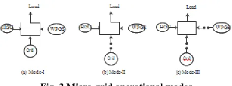
[image:2.612.52.289.373.504.2]Considering these reasons, the technical challenges and methods for addressing them for the system shown in Figure 1 have not been investigated yet. This paper investigates the technical challenges as- sociated with the wind farm and hydro generation based micro-grid system. In order to classify the technical challenges for the micro- grid system under investigation, three operational modes (Figure2) are considered: (a) grid connected system, (b) isolated system with wind power generation, and (c) isolated system without wind power generation.
Fig. 1 The micro-grid system currently under investigation
Fig. 2 Micro-grid operational modes
III. THE MICRO-GRID SYSTEM
The schematic of the micro-grid system shown in Figure 1 consists of a HGU, a WPGS, and two load areas represented as Load-I (3.94 MW, .9 MVar) and Load-II (2.82 MW, 0.84 MVar). The two load areas are connected through a 20.12 km transmission line and the two generating systems are connected
through a 21 km transmission line. The wind turbines are connected to bus 2 using its own transmission lines and a 12.5/66kV, 30 MVA power transformer. Load bus-II is connected to bus 2 and the power is delivered to the load using a 66/12.5kV, 4 MVA power transformer. Load bus-I is connected to bus 1 and the power is delivered to the load using a 66/12.5kV, 5 MVA power transformer. The HGU is connected to bus 1 using a 6.9/66kV, 8MVA power transformer. A conventional synchronous generator, equipped with IEEE standard excitation and governor system, is used for the HGU. A 66kV,1000 MVA grid is connected to bus 1. Both power generation systems operate in grid connected mode. The automatic isolated operation of the HGU is not the current practice of the utility owner, and the WPGS is not allowed to operate in isolated mode. In the event that the grid power is lost due to faults or scheduled maintenance, a black out would result until the HGU comes in operation. Even with the HGU in operation, some load shedding may be necessary since the HGU would not be able to meet the load demand. Therefore, the consequences of the grid outage are the key drivers which dictate the operational modes of the micro- grid system.
IV. OPERATIONALMODES OF THE MICRO-GRID SYSTEM
Technical issues such as control, power balance strategies, oper- ation, protection and storage techniques differ from one micro-grid to another. The main reasons are the integration of high number of distributed power generation units near to the electrical loads, the nature and size of the micro-generation units, and availability of primary energy sources for renewable power generation units.
V. MODELING AND SIMULATION
The components of the identified system are modeled using MATLAB/SIMULINK software tool. The HGU model is the com- bination of the model of synchronous generator, hydro turbine and turbine governor system, and excitation system. The synchronous machine electrical system is modeled in a d-q rotor reference frame with the dynamics of stator, rotor and damper windings [17]. The synchronous machine parameters are obtained from Newfoundland Power, Canada and from [18]. Hydro turbine and turbine governor system model is given in [19]. The parameters for the hydro turbine and penstock are obtained from Newfoundland Power, Canada. The WPGS model consists of dynamic model of nine variable- speed doubly-fed induction generator based wind turbines. Vestas-90 wind turbine parameters are used in the developed wind turbine rotor model [20]. The induction machine electrical system is modeled in a d-q synchronously rotating reference frame [17]. Generator parameters are obtained from [20, 21].
[image:2.612.49.285.540.628.2]A constant impedance load model is used in the system. The parameter information about the line, transformer and load are obtained from the utility company, Newfoundland Power. Simulations for three operational modes (Fig. 2) are performed and the simulation results are presented in the following sections. The measurements presented in the simulation results are in per unit, while the base power is 27 MVA. The simulation was performed for a 60 seconds interval. The wind speed model [22] is used as the wind profile for the wind turbine rotor. WPGS with no output power represents the lack of sufficient wind velocity to generate electric power. The grid is isolated from the system at t=5 seconds because of a fault or regular maintenance in the transmission systems. The fault in the grid transmission systems (unintentional islanding) or their regular maintenance (intentional islanding) is simulated using a three phase circuit breaker with specific time settings.
A. Mode-I: Grid connected mode
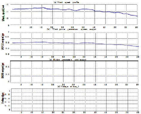
The simulation results for Mode-I are represented in Figures 3(a- d), while WPGS and HGU are connected to the grid. No initial transient indicates the steady-state operation of the system in grid connected mode. Figure 3(a) shows the wind speed profile provided into the wind turbine rotor. Figure 3(c) and 3(b) show the generated power by the HGU, and by the WPGS, while nine wind turbines are in operation. The output of the WPGS varies due to the wind speed variation. Figure 3(d) represents the voltage at bus 1 which is in its rated value. These results indicate that the operation of the HGU and WPGS in grid connected mode is dictated by the grid with the expected system voltages and frequency set by the grid.
Fig. 3 (a) Wind speed profile, (b) WPGS output power, (c) HGU output power, (d) Voltage at bus 1
B. Mode-II: Isolated system with wind power generation
The system operation follows the Mode-I until t=5 seconds.
[image:3.612.51.287.428.619.2]After t=5 seconds, the grid is isolated from the system. Figure
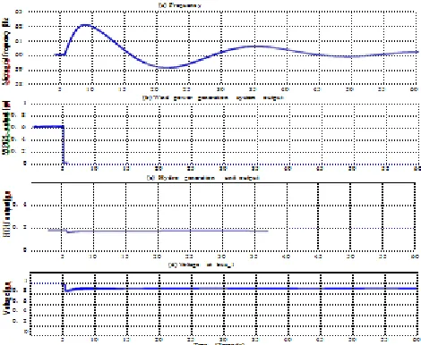
4(a) shows the micro-grid frequency, which is not in an acceptable range for the micro-grid operation. This indicates that
the power generation and consumption is not balanced in the micro-grid system. Figure 4(b) and 4(c) show the power contribution by the two generation units into the micro-gird, while assuming only one wind turbine is in operation in the WPGS after t=5 seconds. As HGU is the firm power generation system, it is decided to operate the HGU during the entire operation. However, the operation of WPGS with one or more wind turbines is decided based on load demand. Voltage at bus 1 is shown in Figure-4(d) which decreases after grid disconnection. This indicates the lack of sufficient reactive power in the micro-grid system, which was actually supplied by the grid in the grid connected mode. More than one wind turbine operating in the WPGS will deliver more active power in the micro-grid system than the load demand. In such case, the reactive power demand will also increase in the micro-grid system which results in more reduction in voltage level at different locations in the micro-grid system.
C. Mode-III: Isolated system without wind power generation
The system operation follows the Mode-I until t=5 seconds. However, at t=5 seconds, the grid is isolated from the system.
Fig. 4. (a) Micro-grid frequency (Hz), (b) WPGS output power, (c) HGU output power, (d) Voltage at bus 1
Concurrently, the WPGS has no output power as there is insufficient wind resource to produce electricity. This mode of operation is simulated, and the results are shown in Figure 5(a-d). Figure 5(a) shows the micro-grid frequency, which is not tolerable by the system. This also indicates that the power generation and consumption in micro-grid system is not balanced. Figure 5(c) shows the HGU output power and the zero output power from the WPGS is shown in Figure 5(b). The voltage level at bus 1 is shown in Figure 5(d) which is much lower than its rated value.
the requirement of additional power from a reliable storage system is essential.
Based on simulation results, the issues related to micro-grid operation of the system under investigation can be summarized as:
• Active power imbalance and/or variation occurs in isolated micro-grid mode when wind power is available. A control scheme is required to maintain active power balance by storing or dumping surplus power. Motor-pump sets can be used to pump water using surplus power. However, a dump load is required to achieve better accuracy in power-frequency balance. • Active power imbalance will occur between generation units and loads when wind power is not available in isolated micro- grid mode. A suitable storage system along with a control scheme is required to maintain power-frequency balance.
• Reactive power is required during isolated micro-grid operation to maintain the expected voltage level at different buses in the micro-grid system. The reactive power demand can be provided by STATCOM during isolated system with wind power generation and by storage unit during isolated system without wind power generation.
In addition, a control coordinator and monitoring system is re- quired for the grid operation. A load flow based micro-grid monitoring and control coordinator scheme can be chosen for the proposed micro-grid system operation.
Fig. 5. (a) Micro-grid frequency (Hz), (b) WPGS output power, (c) HGU output power, (d) Voltage at bus 1
VI. CONCLUSIONS
Micro-grid operation of a system based on renewable power generation units is presented in this paper. The system behavior and technical issues involved with three operational modes in micro-grid scheme are identified and discussed. The investigation is performed based on simulation results using Matlab/Simulink software package. Simulation results indicate that dump load and suitable storage system along with proper control scheme are additionally required for the operation of the study system in a micro-grid scheme. A control coordinator and
monitoring system is also required to monitor micro-grid system state and decide the necessary control action for an operational mode. The required control schemes development for the proposed micro-grid system is currently under investigation by the authors.
VII. ACKNOWLEDGEMENT
This work is supported by a research grant from the National Science and Engineering Research Council (NSERC) of Canada, the Atlantic Innovation Fund (AIF) Canada, and Memorial Univer- sity of Newfoundland. The author also would like to acknowledge the utility company, Newfoundland Power, Canada for providing system data and information presented in this paper.
REFERENCES
[1] T. Ackermann and V. Knyazkin, “Interaction between distributed generation and the distribution network: Operation aspects”, Sec- ond Int. Symp. Distributed Generations: Power System Market Aspects, Stockholm, Sweden, 2002.
[2] C. Abbey, F. Katiraei, C. Brothers, “Integration of distributed generation and wind energy in Canada”, Invited paper IEEE Power Engineering Society General Meeting and Conference, Montreal, Canada, June 18-22, 2006.
[3] Frede Blaabjerg, Remus Teodorescu, Marco Liserre, Adrian V.Timbus, “Overview of control and grid synchronization for dis- tributed power generation systems”, IEEE Transactions on Indus- trial Electronics, Vol. 53, No. 5,October 2006.
[4] F. Katiraei, C. Abbey, Richard Bahry, “Analysis of voltage reg- ulation problem for 25kV distribution network with distributed generation”, IEEE Power Engineering Society General Meeting, Montreal, 2006.
[5] R. H. Lasseter, “Microgrids (distributed power generation)”, IEEE Power Engineering Society Winter Meeting, Vol. 01, pp. 146-149, Columbus, Ohio, Feb 2001.
[6] R. H. Lasseter, “Microgrids”, IEEE Power Engineering Society Winter Meeting , Vol. 01, pp. 305-308, New York, NY, 2002.
[7] F. Katiraei, M. R. Iravani, P. W. Lehn, “Small signal dynamic model of a micro-grid including conventional and electronically interfaced distributed resources”, IET Gener. Transm. Distrib., Vol. 01, Issue 3, pp. 369-378, 2007.
[8] M. Barnes, A. Dimeas, A. Engler, C. Fitzer, N. Hatziargyriou, C. Jones, S. Papathanassiou, M. Vandenbergh, “Micro-grid lab- oratory facilities”, International Conference on Future Power System,November 2005.
[9] N. Hatziargyriou, H. Asano, R. Iravani, C. Marnay, “Micro-grids- Anoverview of ongoing research, development and demonstra- tion projects”, IEEE Power and Energy Magazine, pp. 78-94, July/August 2007..
[10] S. Morozumi,, “Overview of micro-grid research and develop- ment activities in Japan”, A Symposium on Micro-grids,Montreal, June 23, 2006.
[11] “IEEE Recommended Practice for Industrial and Commercial Power System Analysis”, IEEE Standard., IEEE Std 399-1997, 1997.
[12] M. Shahabi, M. R. Haghifam, M. Mohamadian, S. A. Nabavi- Niaki, “Microgrid Dynamic Performance Improvement Using a Doubly Fed Induction Wind Generator”, IEEE Transactions on Energy Conversion,Vol. 24, No. 1, March 2009.
[13] R. Majumder A. Ghosh G. Ledwich F. Zare, “Load sharing and power quality enhanced operation of a distributed micro-grid”, IET Renew. Power Gener., Vol. 3, Iss. 2, pp. 109-119, 2009.
[image:4.612.53.288.374.567.2][15] C. Nayar, M. Tang, W. Suponthana, “Wind/PV/Diesel Micro Grid System implemented in Remote Islands in the Republic of Maldives”, IEEE International Conferences on Sustainable Energy Technologies, Singapore, pp. 1076-1080, November 24-27, 2008.
[16] H. Al-Nasseri, M A Redfern, R. O’Gorman, “Protecting Micro- grid Systems containing Solid-State Converter Generation”, Inter- national Conference on Future Power System, November 2005.
[17] P. C. Krause, O. Wasynczuk, S. D. Sudhoff, “Analysis of Electric Machinery”, IEEE Press, 2002.
[18] F. Katiraei, M. R. Iravani, P. W. Lehn, “Micro-Grid Autonomous Operation During and Subsequent to Islanding Process”, IEEE Transactions on Power Delivery, vol. 20, no. 1, January 2005.
[19] IEEE Working Group on Prime Mover and Energy Supply Models for System Dynamic Performance Studies, “Hydraulic Turbine and Turbine Control Models for Dynamic Studies”, IEEE Transactions on Power Systems, Vol.7, No.1, February, 1992, pp.167-179.
[20] “Mechanical Operating and Maintenance Manual V90 - 3.0 MW, VCRS 60 Hz” , Item no.: 964106.R00, June 2007.
[21] A. Gaillard, P. Poure, S. Saadate, M. Machmoum, “Variable speed DFIG wind energy system for power generation and harmonic current mitigation”, Renewable Energy Journal, Vol. 34, pp. 1545-1553, 2009. [22] M. J. Khan, M. T. Iqbal, “Analysis of a small wind- hydrogen
stand-alone hybrid energy system”, Applied Energy, Vol. 86, pp. 2429-2442, 2009.
AUTHORS
First Author – Dr.K.Ravichandrudu, Krishnaveni Engineering
College for women, Narasaraopet, Ap,India.
Second Author – M.Manasa, Krishnaveni Engineering College
for women, Narasaraopet, Ap,India.
Third Author – Mr.P.Yohan Babu, Krishnaveni Engineering
College for women, Narasaraopet, Ap,India.
Fourth Author – Mr.P.Yohan Babu, Reaserch scholar,SVU