International Journal of Emerging Technology and Advanced Engineering
Website: www.ijetae.com (ISSN 2250-2459,ISO 9001:2008 Certified Journal, Volume 3, Issue 5, May 2013)
225
Microprocessor Based Differential Protection Of A Feeder
Depending On Phase Comparison Of Current
Chandrani Das
1 1Department of Electrical Engineering, B.P.Poddar Institute of Management & Technology, Kolkata, West Bengal
Abstract—Aim of this paper is to protect a transmission line section/feeder from internal faults by means of differential protection through a microprocessor. The conventional differential relay operates on the circulating current principle, which involves a direct comparison of the magnitude and phase of the currents entering and leaving the protected equipment or line section. The present scheme is based on the difference in wave pattern of the secondary currents of the two CTs which will be 180º or more than that during internal faults and less than 180º during external faults or no fault.
Keywords— CT, Differential protection, Fault, Microprocessor,Phase comparison.
I. INTRODUCTION
Different schemes used for differential type of protection of feeder are - pilot wire protection of line, use of two relays, one at each end, pilot –wire protection of a two-ended line (circulating current scheme), basic scheme of Pilot Wire Feeder protection. Other methods are also suggested to achieve the purpose of differential relaying. A unique new approach [1] to numerical current differential line protection is there that offers improved performance over the conventional percentage restraint approach. This current differential algorithm employs a new method of Fourier calculation that allows the protective system to use ―partial‖ Fourier signals called ―phaselets‖ rather than the normal fixed window Fourier approach. The phaselet approach also facilitates in the calculation of a confidence level for the measured currents. This permits the current differential system to adapt its operating characteristics based on the quality of the measured current values. Another approach to current differential protection of transmission lines is to transform the instantaneous line current(s) by using a moving window averaging technique [2]. If the time span of moving window is equal to one-cycle time, then the steady-state value of the transformed current is zero for a periodic signal which is composed of fundamental and harmonic frequencies. Signal distortions (e.g., a fault) cause the transformed currents to deviate from the nominal zero value. This permits the development of a sensitive, secure, fast, and yet simple current differential protection scheme.
The scheme can be applied into series-compensated transmission lines. Zhenyu Chen presented a paper [3] on the Intelligence Structure of Current Differential Protection in Transmission Line of UHV Based on Agent. Here the action criterions of Phase-segregated current differential protection in Transmission line of UHV include the criterion based on whole current, instantaneous value of fault and other changing from it. In different areas of fault, reach criterion has different reliability and sensitivity. On the basis of deeply analyses and study of the principle for Phase-segregated current differential protection, this paper combines intelligence Agent technology, and creates an
intelligent protection structure which can choose
International Journal of Emerging Technology and Advanced Engineering
Website: www.ijetae.com (ISSN 2250-2459,ISO 9001:2008 Certified Journal, Volume 3, Issue 5, May 2013)
226 The RED670 IED (Intelligent Electronic Device) [6] is designed for protection, monitoring and control of overhead lines and cables. In addition, this IED is capable of handling transformer feeders, generator and transformer blocks. It provides an extensive functionality with configuration opportunities and expandable hardware to meet system specific requirements. There is another approach [7] which describes the principle of sampled value-differential protection and discusses the selections of S and R values in the protection of short transmission lines. The basic selective rule is to ensure the restraint effectiveness of sampled value-differential protection equal or superior to the corresponding phasor-differential protection during external faults. Investigation shows the proposed method‘s ability to avoid CT saturation and bad data is superior to that of the phasor methods. A new short transmission line protection system based on the proposed protection has been developed for GeZhouBa Hydroelectric Power Plant. Test results in the Electrical Power Dynamic Laboratory (EPDL) verify the protection performance. This system is now being put into trial operation. A new microcomputer-based approach for pilot differential protection of transmission lines [8] presents a theoretical and experimental study of a new technique for pilot differential protection of transmission lines. The difference currents obtained from post- and pre-fault line currents, adjusted by calculated charging currents, are used to minimize the desensitizing effect of load and line charging currents. The experimental results are from a laboratory 16-bit microcomputer-based relay that was developed to test some of the features of this new approach. Off-line test results for various types of faults on a lumped parameter long transmission line model and real-time test results for a short transmission line model are presented. An adaptive current differential principle for transmission line [9] is there with high performance and high reliability, which combines instantaneous value with fault component instantaneous value. In the principle, the parameters change adaptively with the dynamic variations of power system. To implement the protection scheme, an all-purpose protection hardware system platform with opening ability is
proposed. The adaptive Ethernet network and
telecommunication module with high-performance of data transmission is employed to achieve better characters. This protection device is extensively tested. An improved steady current differential protection criterion is also proposed [10].
The present scheme is based on the difference in wave pattern of the secondary currents of the two current transformers (CTs) which will be 180º or more than that during internal faults and less than 180º during external faults or no fault. This is a microprocessor based protection scheme. The phase difference the two waveforms is measured using a microprocessor and an output signal is sent accordingly to the trip circuit. This is a fast acting and reliable protection scheme.
II. METHOD OF APPROACH
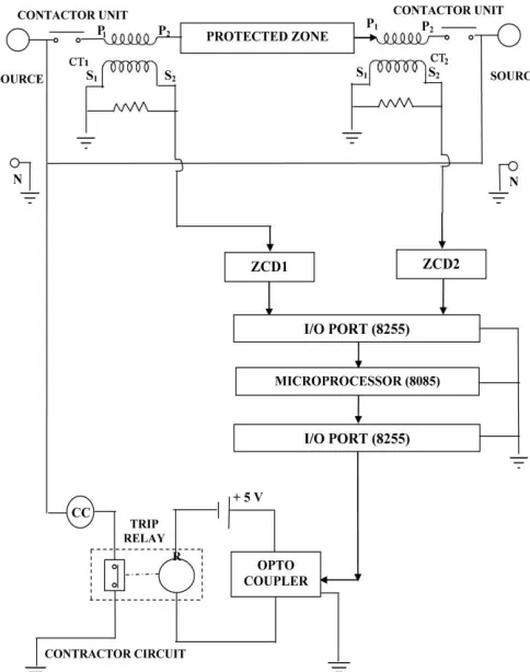
[image:2.612.328.570.318.625.2]This scheme is based on difference in wave pattern of the secondary currents of the two CTs instead of the magnitude difference of the two currents as in the conventional electromechanical relays.
International Journal of Emerging Technology and Advanced Engineering
Website: www.ijetae.com (ISSN 2250-2459,ISO 9001:2008 Certified Journal, Volume 3, Issue 5, May 2013)
227 Hence, the difficulties associated with the magnitude difference of CT secondary currents do not arise. Moreover, introduction of microprocessor in this scheme produces a very fast acting and reliable protection scheme. Whenever there is fault in the protected region bounded by the location of two CTs, the fault will be fed from both sides (assuming source of supply at the both ends) and under internal fault conditions, the direction of the fault current must be opposite at the two ends. As a result, the direction of flow of current in one of the two CT primaries becomes opposite to the other so that the voltage waves available across the burden to the two CT secondary are shifted by at least 180. The phenomenon is detected by microprocessor to develop a trip signal and there by to isolate the faulty section from healthy part. The scheme is valid for feeder, transmission line etc.
III. SPECIFICATION OF SYSTEM COMPONENTS
Microprocessor Kit: SD-1234
Current Transformer (CT):Rating – 5/1, Frequency – 50 Hz, Line - 660, Class – 1, Burden - 15 VA, Serial No. – 12943 Make - Electrical Electronics Enterprises, Calcutta
Transistor: SL-100 Optocoupler: MCT 2E
Rheostat: Rating - Constant/Intermittent, Amp. – 8 Relay: Voltage – 6V, Current – 1A
Diode: IN – 4001 Power Supply: 5V ZCD: LM 339
IV. THE PROPOSED SCHEME
In actual conventional system, the two CT primaries are connected in series and whenever there occurs any internal fault, the current through the two CT primaries are in the opposite directions.
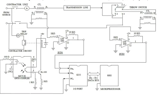
In the laboratory, this actual faulty situation cannot be created easily. The phenomenon of fault condition may be simulated by making the current reversal through one of the two CTs using throw switch arrangement (Figure 2).
When the rocker arm is positioned on the terminals (3) and (4), the current in the two CT primaries are in the same direction and when the same is in contact with the terminals (1) and (2), the direction of current in CT2 is reversed. With this arrangement of throw switch, the fault may be simulated in the laboratory. The mechanism of operation of the scheme is described here.
The voltage wave available across the burden of the two CTs has to be fed to the microprocessor through two zero crossing detectors (ZCDs), the outputs of which are square waves. Microprocessor receives the signals from the ZCDs through two pins of the input port A and detects the faulty condition by suitable software. Under normal and through fault conditions, the voltage waves are virtually in phase and the microprocessor displays the 01 as an indication of the healthy condition. When fault occurs, it generates a control signal which through an optocoupler energizes the coil of a simple trip relay having normally closed contacts and the moving contacts are attracted. Then by the trip circuit of the contactor, trip coil of the contactor circuit is de-energized to release the contacts of the contactor connected to the main line to isolate the faulty transmission line section from the source.
For normally closed relay contacts, the trip circuit of the contactor is closed, the trip coil of the contactor circuit is energized by the voltage source of the main line and the contacts are closed allowing the current to flow from the voltage source to the protected transmission line section. But when fault occurs, the contacts of the contactor are opened sequentially to cut the connection between source and protected zone. Thus the feeding of fault current by the source is stopped.
The system software may be divided into two different parts – (1) To determine the delay number corresponding to a phase difference of 180 degrees δ(180)and (2) To develop the software for finding the phase difference δ(θ) between two current waveforms and hence to detect the fault condition.
International Journal of Emerging Technology and Advanced Engineering
Website: www.ijetae.com (ISSN 2250-2459,ISO 9001:2008 Certified Journal, Volume 3, Issue 5, May 2013)
[image:4.612.50.563.128.439.2]228
Figure 2: Circuit diagram of system hardware
International Journal of Emerging Technology and Advanced Engineering
Website: www.ijetae.com (ISSN 2250-2459,ISO 9001:2008 Certified Journal, Volume 3, Issue 5, May 2013)
International Journal of Emerging Technology and Advanced Engineering
Website: www.ijetae.com (ISSN 2250-2459,ISO 9001:2008 Certified Journal, Volume 3, Issue 5, May 2013)
230
Flow Chart for subroutine to find out the zero crossing instant at the rising edge of the waveform
Flow Chart for subroutine for a small delay
V. EXPERIMENTAL RESULT
TABLE SHOWING VALUES OF PHASE DIFFERENCE δ(θ), PHASE DIFFERENCE CORRESPONDING TO 180º i.e. δ(180) FOR DIFFERENT
VALUES OF DELAY NUMBER ‗Z‘ STORED IN REGISTER D
Delay Number stored at Register D
Phase Difference corresponding to 180º, δ(180)
Phase Difference between two current waveforms obtained from two CTs, δ(θ)
Under normal condition Under faulty condition
01 H E4 H 0D H EA H
International Journal of Emerging Technology and Advanced Engineering
Website: www.ijetae.com (ISSN 2250-2459,ISO 9001:2008 Certified Journal, Volume 3, Issue 5, May 2013)
231
VI. DISCUSSION
The voltages obtained across the burdens connected to the CT secondaries were always adjusted to be 2.5 V. This was done to save the ZCDs from overvoltages (more than 5V) appearing at the input pins of ZCDs. So even if the CT primary current reduces to half the rated value of the system, CT secondary voltage becomes twice that of the previous value i.e. it becomes 5V. Thus ZCD is protected from overvoltages.
CTs of proper ratio are chosen according to the maximum current (load current) magnitude for a system. Otherwise, if the magnitude of the current is more than the magnetizing current of CT, the CT will saturate giving wrong result.
Since the transmission line was a simulated one, obtained by connecting equivalent capacitances and inductances, the current obtained from the 2nd CT secondary was leading in phase than that of the 1st CT secondary due to capacitive effect under internal fault condition.
Here delay number in the delay subroutine is taken as small as possible (here it is 01H or 02H) in order to give a frequent check on the phase of the waveform from obtained from CT2, so that fault can be detected as quickly as possible and the system is protected from damage.
Here δ(180) will change with supply frequency variation. So before switching on, it is necessary to measure δ(180) first to have proper comparison between δ(180) and δ(θ).
One of the limitations of the scheme is that it is valid for two ended supply only, not for one ended supply. For one ended supply, necessary changes must be made.
This scheme is basically valid for feeder protection, but depending on availability factor, transmission line is chosen for this project. Again this type of differential protection is valid for short line length (18 to 30 Km.). Above this length the capacitance of long pilot wires becomes significant and thus causes difficulty in protection scheme. It is a prototype of the actual system, and thus necessary modifications must be taken in practical applications.
This scheme is faster than the conventional schemes and so quick detection of faults and disconnection of faulty section from healthy part is possible. Here phase difference between the waveforms is considered. So the difficulties associated with magnitude difference of CT currents do not arise.
The same scheme can be applied for differential protection of a generator, transformer etc. with necessary modifications.
REFERENCES
[1] M. G. Adamiak, G. E. Alexander, W. Premerlani. ‗A New Approach toCurrent Differential Protection for Transmission Lines‘. Copyright 1999 IEEE. Published in the Proceedings of the Hawaii‘ International Conference on System Sciences, January 5-8, 1999, Maui, Hawaii.
[2] Dambhare, S., Soman, S.A., Chandorkar, M.C.‗Current Differential Protection of Transmission Line using The Moving Window Averaging Technique‘, IEEE Transactions on Power Delivery, Vol 25, Issue:2, p. 610- 620, 13 November 2009.
[3] Zhenyu Chen. ‗Study on the Intelligence Structure of Current Differential Protection in Transmission Line of UHV Based on Agent‘, Modern Applied Science, Vol 1, No 2 (2007), ISSN 1913-1844 (Print), ISSN 1913-1852 (Online).
[4] Mohamed Mamdouh Abdel Aziza, Ahmed Faheem Zobaa, Doaa Khalil Ibrahima and Mohammed Mohammed Awad. ‗Transmission lines differential protection based on the energy conservation law‘, Electric Power Systems Research, Volume 78, Issue 11, November 2008, p. 1865-1872.
[5] Roberts, Benmouyal, Altuve-ferrer, Folkers, Tziouvaras ‗Line differential protection system for a power transmission line‘, United States Patent 6518767, 02/11/2003.
[6] ABB Product Guide. ‗Line differential protection RED670‘. [7] J.C. Yang, X.G. Yin, D.S. Chen, Z. Zhang. ‗The Protection of Short
Transmission Line Based on Sampled Value-Differential Technique‘, International Journal of Power and Energy Systems - 2005 3.203-3406.
[8] Mustahsan Mi, Patrick J McCleer. ‗A new microcomputer-based approach for pilot differential protection of transmission lines‘, Elsevier, Computers & Electrical Engineering, Volume 13, Issues (3-4) 1987, p.129-13.
[9] Lei Shi, Gang Wang, Jiancang Zhao. ‗Adaptive current differential protection for transmission lines‘, Eighth IEE International Conference on Developments in Power System Protection, Amsterdam, Netherlands, 5-8 April 2004, Issue CP500, Volume 2, p.424–427.
[10] TANG Jun WANG Xiao-ru. ‗Current Differential Protection Criterion Using Steady Currents for Heavy-load Line With High Fault Resistance‘, Proceeding of the CSEE 2008, Issue 28(4), p. 72-77.
[11] Ramesh S. Gaonkar. ‗Micorprocessor Archietecture, Programming and Applications with the 8085‘, 3rd Edition, 1997, Penram International Publication.