Parametric Study on Geometrical Arrangement of Sister Hole
Kamil ABDULLAH*
1, a, Firdauz AMON
1,band Mas Fawzi MOHD ALI
1,c1Center for Energy and Industrial Environmental Studies Faculty of Mechanical and Manufacturing
Universiti Tun Hussein Onn Malaysia 86400 Parit Raja, Johor MALAYSIA
amkamil@uthm.edu.my, bfirdauz.amon@gmail.com, cfawzi@uthm.edu.my
Keywords: film cooling, sister holes, counter rotating vortex pair (CRVP)
Abstract. Modern gas turbines require a sophisticated cooling scheme to remove the heat from its
component to ensure it durability. One of the common techniques applied in the cooling scheme is film cooling The present study focuses numerical investigation of an sister cooling hole design. The investigations make use of commercial CFD software, ANSYS CFX. The numerical investigations have been carried out at Reynolds number, Re = 21,000 involving three differens blowing ratios, BR = 0.5, 1.0, and 1.5. Four different cases have been considered; STA, STB STC and SH. The results show promising improvement in terms of film cooling effectiveness with the implementation of sister holes in certain geometrical arrangements.
Introduction
Gas turbine engine has become one of the well-known devices that carry important role in human life. It benefits human in the sector of transportation, power generation, and much more applications. One of the familiar applications of the gas turbine engines are in aircraft. It is used to convert the high pressure and high temperature combustion air from the combustion chamber to mechanical energy through the turbine. High turbine inlet temperature is necessary to provide more available energy to be converted by the turbine. Modern gas turbine operates at very high temperature which usually exceeds the metallurgical limit of turbine blade components material. The extremely high temperature is exposing it to excessive thermal stresses which effecting its durability. Therefore, modern gas turbines require a sophisticated cooling scheme to remove the heat from its component. One of the techniques used in the cooling scheme is film cooling where coolant, in the form of compressed air is injected out from the blade body to perform a thin layer of cool air covering the blade surface. This layer will prevent direct contact between the hot gas and blade surface thus reducing the surface temperature of the component. Researches on film cooling have been carried out for more than 40 years and modifications of the film cooling hole and also its surrounding geometries has been made based on the same objective; to increase the efficiency of the gas turbine.
Literature Review
effectiveness distribution [2]. Kusterer, K. et al. [3] reported the effect of using multiple holes or also known as double-jet ejection on the film cooling effectiveness. It was observed that the effects double-jet ejection minimize the growth of counter rotating vortex pair lead to better film cooling effectiveness. Heidmann, D. [4] in his work on the anti-vortex cooling hole discovers that the addition of the secondary holes improve the film cooling effectiveness while minimizing the effect of the primary counter rotating vortex pair. The study also reported that at high blowing ratio, positioning the holes immediately at the exit primary hole gave the optimum film cooling effectiveness. Instead of considering two cooling hole, Elly, M. and Jubran, B.A. [5] have carried out an investigation involving sister holes; primary hole surrounded by a pair or two pairs of small holes. The research evaluates the laterally averaged film cooling effectiveness and the centerline effectiveness at various locations of the sister holes. The study concluded that the addition of sister holes significantly increase the film cooling effectiveness compared to the single hole for all cases. In addition, the sister holes provide a significant improvements on the film cooling effectiveness at the near hole regions [5].
Methodology
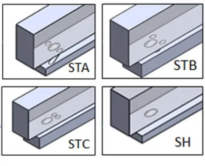
Computational Domains. Three sister holes
arrangements have been considered in the present study focuses to investigate the effect of hole arrangements involving; a) arrangement A (STA), b) arrangement B (STB), and c) arrangement C (STC). On top of the aforementioned cases, a cylindrical film cooling case has also been considered as a baseline case known in this writing as SH. Figure 1 shows the hole arrangements involved in the present study together. The computational domain consists of main film
cooling hole accompanied with pair of sister hole inclined at θ = 35° toward the main stream direction.
The three different sets of sister holes considered in present study were arranged at different x/D locations based on lateral axis angle, . Prior to the analyses, mesh dependency test has been carried out to ensure the accuracy of the numerical procedure. All of the models consist of not less than 33000 number of nodes.
Numerical Setup. The present numerical
[image:2.595.339.539.291.453.2]investigations were carried out through ANSYS CFX software. Reynolds Average Navier Stokes analysis has been applied with the employment of Shear Stress Transport turbulence model. The boundary conditions applied in the present study make used most of the one in the work of Elly and Jubran [5] as shown in Table 1. The secondary mass flow rate for the anti-vortex hole have been determine with the assumption that all the cooling holes to have the same blowing ratio and the sum of the required mass flow rate of each hole have been applied at the secondary inlet of the computational domain.
Table 1: Details on the boundary conditions
Reynold’s Number, ReD 21,000
Mainstream Velocity, U∞ 10 m/s
Mainstream Temp., T∞ 353.15 K
Mainstream Turbulent.
Intensity, Tu 1%
Blowing Ratio, BR 0.5, 1.0, 1.5
Secondary Inlet Temp., Tc 293.15 K
Results and Discussion
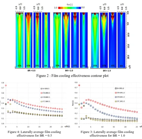
Film Cooling Effectiveness. Figure 2 shows the
[image:3.595.59.528.84.543.2]film cooling effectiveness contour for all cases considered in the present study. Qualitatively, all the sister hole arrangements produces better coverage in comparison to the singe hole case at all blowing ratios. The effectiveness decline significantly as the blowing ratio increses for the case of SH but not so for all other arranements. Figures 3-5 show the laterally average film cooling effectiveness for blowing ratio, BR = 0.5, 1.0, and 1.5, respectively. The film cooling effectiveness observed to be highest at lowest blowing ratio for all cases except for the STA. Although STA produces nearly consistent laterally average film cooling effectiveness value at x/D < 10 at all blowing ratios, the film cooling effectiveness can be observed to decay faster at higher blowing ratio. Consistent with the other cases, BR = 0.5 produces better effectiveness at x/D > 10 followed by BR = 1.0 and 2.0. Comparison between the sister hole arrangements (STA, STB and STC) and the SH show that
[image:3.595.110.491.84.329.2]Figure 2 : Film cooling effectiveness contour plot
Figure 3: Laterally average film cooling effectiveness for BR = 1.0 Figure 4: Laterally average film cooling
effectiveness for BR = 0.5
[image:3.595.298.541.351.537.2]additional sister hole in STA and STB produces significant improvement in terms of film cooling effectiveness but not for the STC at all considered blowing ratios. The location of the sister hole which is beside the main cooling in STA and STB helps to spread the coolant laterally resulting better film cooling effectiveness. The position of the sister holes which is wider for the case of STA in comparison with STB obviously resulting better film cooling effectiveness as been shown in Figures 3-5. However, the STC shows little advantages in comparison to the SH case. The location of sister holes immediately downstream of the main cooling hole preventing the secondary air to be spread laterally thus resulting insignificant improvement in terms of film cooling effectiveness. In general, the results clearly describe that the implementation of sister holes in certain geometrical arrangements provide significant increases in the film cooling effectiveness in comparison to the single hole film cooling.
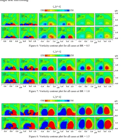
Figure 6: Vorticity contour plot for all cases at BR = 0.5
[image:4.595.56.549.216.784.2]Figure 7: Vorticity contour plot for all cases at BR = 1.0
Vorticity and Flow Field. Figures 6-8 show the vorticity contour plots on YZ plane at x/D = 01, 03 and 07 for all cases. The formation of CRVP can be clearly observed for the case of SH at all blowing ratios. Stronger CRVP which is expected at higher blowing ratio is indicated by higher vorticity value and wider coverage of the vorticity plot. The strength of the CRVP will enhance the entrainments of the mainstream air consequently hindering the film cooling effectiveness as been discussed in the previous section. In addition to the CRVP structure, additional vortical structure can be observed for the STA and STB at x/D = 01 at all blowing ratio. The trace of these additional structure can still be observed at x/D = 03, but only at BR = 2.0. At lower blowing ratio, BR = 0.5 and 1.0, these vortices are too weak and have been eliminated by the CRVP structure. Although non-exist, the additional vortical structure originated from sister hole does altered the flow CRVP structure as been shown in Figure 6 and 7. The altered flow field provides more coolant coverage at the near wall region resulting better spread of the coolant which are in-parallel to the results shown in Figures 2-5. In the case of STC, the additional vortical structure originated from the sister hole cannot be observed at any locations and blowing ratios. It is believed that the aforementioned vortical structure is eliminated by the CRVP due to the superior strength between those two.
Conclusion
The present study involved an numerical investigation of an sister cooling hole design. The numerical investigation is made used of ANSYS CFX ver. 14. Steady state Reynolds Averaged Navier Stokes (RANS) has been used for the simulation involving the Reynolds number, Re = 21,000 at blowing ratios, BR = 0.5, 1.0, and 1.5. Four different computational models have been considered in the present study; STA, STB STC and SH. The results show that the implementation of sister holes in certain geometrical arrangements provide significant increases in the film cooling effectiveness in comparison to the single hole film cooling. STA has been observed to provide the best film cooling coverage followed by STB and STC. The location of the sister hole in STA helps to spread the secondary air in the lateral area improving the film cooling coverage. In addition, the location of the sister hole also helps to alter the CRVP structure in a way that it reducing the lift-off effect limiting the entrainment of the mainstream air.
Acknowledgement
The author would like to thank both Universiti Tun Hussien Onn Malaysia (UTHM) and Ministry of Education of Malaysia (MoE) for the financial support through Research Acculturation Grant Scheme (R036).
References
[1] Kurosaka, M., 1997, “Contoured Holes for Film Cooling: The Effect of Kidney-Shaped Vortices’’, Technical Report, University of Washington, Seatttle, WA.
[2] Jung, I. S. and Lee, J., S., 1999, “Effects Of orientation Angles on Film Cooling Over a Flat Plate: Boundary Layer Temperature Distributions and Adiabatic Film Cooling Effectiveness,” ASME Journal of Turbomachinery, Vol. 122, pp. 153-160.
[3] Kusterer, K., Bohn, D,. Sugimoto, T., and Tanaka, R., 2007, “Double-jet Ejection of Film Air for Improved Film Cooling”, ASME Journal of Turbomachinery, Vol. 29, pp. 809-815
[4] Heidmann, J. D