AN ENHANCED UML CONSISTENCY CHECKER USING LOGICAL
APPROACH
NORAINI BINTI IBRAHIM
A thesis submitted in
fulfillment of the requirement for the award of the
Doctor of Philosophy in Information Technology
Faculty of Computer Science and Information Technology
Universiti Tun Hussein Onn Malaysia
v
ABSTRACT
In developing an information system, software specification is one of the common
activities to any system development methodologies. A software model is among the
ways to specify software functionalities and constraints. It is constructed as a way to
understand the software prior to actually building or modifying it, and it can help in
reducing defect density in the software design. In an object oriented based
development, Unified Modeling Language (UML) is a famous language used for
visualising, capturing and documenting software requirements. Currently, UML has
a set of fourteen (14) diagrams that permits modellers to describe different aspects of
a system. Each diagram comprises of graphical notations that adhered to UML
elements. These situations rendered UML model vulnerable to consistency problems
where two or more overlapping elements of different diagrams are not jointly
satisfiable. Even though the research in consistency between UML diagrams is
rapidly increased, there is still lack of researches of consistency based on use case in
use case diagram. UML consistency management is becoming a difficult task
because UML itself lacks of formal syntax and semantics and current approaches
using simplified version of UML make their approaches hard to implement in CASE
(Computer-aided Software Engineering) tool environment. Due to those problems,
this research introduces formal syntactical rules to UML elements of four (4) most
popular UML diagrams used by UML practitioners: use case diagram, activity
diagram, sequence diagram and class diagram. Referring to the formal syntactical
rules for UML elements, formal horizontal consistency rules based on use case are
also specified. The formal specifications introduced in this research are using logical
approach. Based on the syntactical and horizontal consistency rules, UML Checker is
implemented in the CASE tool environment. Then, the UML Checker is validated by
using UML model of Lecture Assessment System (LAS) as a case study. It shows
that the UML Checker can detect inconsistencies between four (4) UML diagrams in
vi
ABSTRAK
Dalam membangunkan sebuah sistem maklumat, menyatakan spesifikasi sesebuah
perisian tersebut merupakan aktiviti yang perlu dilakukan dalam mana-mana
metodologi pembangunan sistem. Menghasilkan model perisian merupakan antara
cara yang digunakan untuk menyatakan fungsi dan kekangan sesebuah perisian. Ia
dihasilkan sebagai salah satu cara untuk memahami perisian sebelum perisian
tersebut dibangunkan atau diubahsuai, serta dapat membantu dalam mengurangkan
kecacatan dalam reka bentuk perisian. Dalam pembangunan sistem berorientasikan
objek, Unified Modeling Language (UML) merupakan bahasa popular yang
digunakan untuk menggambarkan, mewakilkan dan mendokumentasikan keperluan
sesebuah perisian. Sehingga kini, UML mempunyai empat belas (14) rajah yang
menerangkan pelbagai aspek sesebuah sistem. Setiap rajah pula mengandungi
tatatanda grafik yang terdiri daripada elemen-elemen UML. Keadaan ini
menyebabkan model UML terdedah kepada keadaan tidak konsisten apabila dua atau
lebih elemen yang bertindan pada rajah berbeza tidak sepadan. Walaupun
penyelidikan berkaitan konsistensi antara rajah telah meningkat dengan pantas,
masih terdapat kekurangan penyelidikan konsistensi berasaskan kes guna dalam rajah
kes guna. Pengurusan konsistensi UML menjadi sukar kerana UML sendiri
kekurangan sintaks dan semantik formal dan pendekatan terkini menggunakan versi
bukan piawaian yang menyebabkan pendekatan tersebut sukar diimplimentasikan
kepada peralatan bantuan komputer berasaskan kejuruteraan perisian (CASE atau
Computer-aided Software Engineering). Justeru, penyelidikan ini memperkenalkan peraturan sintaksis secara formal kepada elemen bagi empat (4) rajah UML yang
paling kerap digunakan oleh pengamal UML iaitu rajah kes guna, rajah aktiviti, rajah
jujukan dan rajah kelas. Berdasarkan peraturan sintaksis secara formal bagi elemen
setiap rajah, peraturan konsistensi mendatar berasaskan kes guna secara formal
antara rajah UML tersebut turut dihasilkan. Spesifikasi formal yang dihasilkan dalam
vii
dan konsistensi mendatar tersebut, UML Checker diimplementasikan dalam
persekitaran peralatan bantuan komputer berasaskan kejuruteraan perisian (CASE).
Kemudian, UML Checker ditentusahkan menggunakan model UML untuk Lecture
Assessment System (LAS) sebagai kajian kes. Hasilnya menunjukkan bahawa UML Checker tersebut boleh mengesan masalah konsistensi antara empat (4) rajah UML
viii
CONTENTS
TITLE i
DECLARATION ii
DEDICATION iii
ACKNOWLEDGEMENT iv
ABSTRACT v
ABSTRAK vi
CONTENTS viii
LIST OF PUBLICATIONS xiii
LIST OF TABLES xv
LIST OF FIGURES xvii
LIST OF ALGORITHMS xix
LIST OF SYMBOLS AND ABBREVIATIONS xx
LIST OF APPENDICES xxi
CHAPTER 1 INTRODUCTION 1
1.1 Research motivations 3
1.2 Aim and objectives of study 5
1.3 Scope of study 6
1.4 Significance of study 7
1.5 Chapter summary 8
1.6 Thesis outline 8
CHAPTER 2 LITERATURE REVIEW 10
2.1 Software specification and software model 10
2.2 Unified Modeling Language (UML) 11
2.2.1 UML model 12
2.3 UML consistency definition 23
2.4 UML consistency management framework 25
ix
2.4.2 Comparative studies in consistency
management 31
2.5 Chapter summary 33
CHAPTER 3 RESEARCH METHODOLOGY 35
3.1 Research framework 35
3.2 Formalization of syntactical rules of UML
elements for UML diagrams 36
3.3 Formalization of horizontal consistency rules 37
3.4 Implementation of the syntactical and horizontal
consistency rules in tool environment 37
3.5 Validation of UML Checker using UML model in
a case study 38
3.6 Chapter summary 39
CHAPTER 4 FORMALIZATION OF SYNTACTICAL RULES AND
CONSISTENCY RULES 40
4.1 Formalization of UML elements and their
syntactical rules 40
4.1.1 UML class diagram (CD) 42
4.1.2 UML use case diagram (UCD) 44
4.1.3 UML activity diagram (AD) 46
4.1.4 UML sequence diagram (SD) 49
4.2 Formalization of horizontal consistency rules 52
4.3 Chapter summary 84
CHAPTER 5 IMPLEMENTATION OF UML CHECKER 85
5.1 Overview of UML Checker 85
5.2 Editor 86
5.3 Checker 92
5.3.1 Algorithm for consistency rules between
UCD and AD 92
5.3.2 Algorithm for consistency rules between
UCD and SD 95
5.3.3 Algorithm for consistency rules between
x
5.3.4 Algorithm for consistency rules between
AD and SD 98
5.3.5 Algorithm for consistency rules between
AD and CD 101
5.3.6 Algorithm for consistency rules between
SD and CD 103
5.4 Report Generator 105
5.4.1 Report generated for consistency rules
between UCD and AD 105
5.4.2 Report generated for consistency rules
between UCD and AD 108
5.4.3 Report generated for consistency rules
between UCD and CD 109
5.4.4 Report generated for consistency rules
between AD and SD 110
5.4.5 Report generated for consistency rules
between AD and CD 111
5.4.6 Report generated for consistency rules
between SD and CD 113
5.5 Chapter summary 114
CHAPTER 6 EVALUATION OF UML CHECKER 116
6.1 UML model for LAS 116
6.2 Consistency verification between UCD and AD 118
6.3 Consistency verification between UCD and SD 121
6.4 Consistency verification between UCD and CD 123
6.5 Consistency verification between AD and SD 124
6.6 Consistency verification between AD and CD 126
6.7 Consistency verification between SD and CD 127
6.8 Validation of a UML model without and by using
UML Checker 129
6.9 Comparison between several researchers’ findings
on issues in detecting inconsistency among four
xi
6.9.1 Comparative studies on consistency
between UCD and AD (UCD-AD) 130
6.9.2 Comparative studies of consistency
between UCD and SD (UCD-SD) 132
6.9.3 Comparative studies on consistency
between UCD and CD (UCD-CD) 133
6.9.4 Comparative studies on consistency
between AD and SD (AD-SD) 134
6.9.5 Comparative studies on consistency
between AD and CD (AD-CD) 135
6.9.6 Comparative studies on consistency
between SD and CD (SD-CD) 137
6.10 Chapter summary 140
CHAPTER 7 CONCLUSION AND FUTURE WORK 141
7.1 Research summary 141
7.2 Achievement of objectives 141
7.2.1 Objective 1: Formalization of UML
elements for UML use case diagram,
activity diagram, sequence diagram and
class diagram and their syntactical rules
into logical specification 141
7.2.2 Objective 2: Formalization of horizontal
consistency rules between UML use case
diagram, activity diagram, sequence
diagram and class diagram based on UML
elements in Objective 1 into logical
specification 142
7.2.3 Objective 3: Implementation of syntactical
and horizontal consistency rules in UML
Checker 142
7.2.4 Objective 4: Validation of UML Checker
using a UML model 143
7.3 Contribution 143
xii
7.5 Summary 144
REFERENCES 145
APPENDIX 150
xiii
LIST OF PUBLICATIONS
Journal:
(i) Noraini Ibrahim, Rosziati Ibrahim, Mohd Zainuri Saringat, Dzahar Mansor and Tutut Herawan. (2012). “Use Case Driven based Rules in Ensuring
Consistency of UML Model.” In AWERProcedia Information Technology
and Computer Science. vol. 1, pp. 1485-1491.
(ii) Noraini Ibrahim, Rosziati Ibrahim, Mohd Zainuri Saringat, Dzahar Mansor and Tutut Herawan. (2011). “Consistency Rules between UML Use Case and
Activity Diagram Using Logical Approach.” In International Journal of
Software Engineering and Its Applications. Science and Engineering Support
Center. vol. 5, no. 3, pp. 119-134.
Proceedings:
(i) Noraini Ibrahim, Rosziati Ibrahim, Mohd Zainuri Saringat, Dzahar Mansor and Tutut Herawan. (2011). “Definition of Consistency Rules between UML
Use Case and Activity Diagram.” In T.-h. Kim, et al. (Eds.). Ubiquitous
Computing and Multimedia Applications. CCIS, Springer Berlin /
Heidelberg. vol. 151/ 2011, pp. 498-508.
(ii) Noraini Ibrahim, Rosziati Ibrahim, Mohd Zainuri Saringat, Dzahar Mansor and Tutut Herawan. (2010). “On Well-Formedness Rules for UML Use Case
Diagram.” In F. Wang, et al. (Eds.). Web Information Systems and Mining.
LNCS, Springer Berlin / Heidelberg. vol. 6318/ 2010, pp. 432-439. Cited by
2.
(iii) Noraini Ibrahim and Rosziati Ibrahim. (2009). “Checking Inconsistencies
in UML Diagrams.” Software Engineering Postgraduate Workshop (SEPOW
xiv
(iv) Noraini Ibrahim and Rosziati Ibrahim. (2009). “Semantic Rules of UML Specification.” Malaysian Technical Universities Conference on Engineering
and Technology (MUCEET 2009). Kuantan, Pahang.
(v) Noraini Ibrahim, Rosziati Ibrahim and Dzahar Mansor. (2009). “Formalization of Well-Formedness Rules for UML Use Case Diagram.”
The 5th International Conference of Information and Communication
Technology and Systems (ICTS) 2009. Surabaya, Indonesia. pp. 127-132.
(vi) Noraini Ibrahim, Rosziati Ibrahim and Dzahar Mansor. (2009). Well-Formedness Rules for UML Use Case Diagram. Proceeding of International
Industrial Informatics Seminar (IIS) 2009. Yogyakarta, Indonesia. pp.
xv
LIST OF TABLES
2.1 Concrete example of consistency problem classification
(Lucas, et al., 2009)... 23
2.2 Researchers involved in UML consistency management of four (4) UML diagrams ... 26
3.1 Description of LAS ... 38
4.1 Overview of UML elements and their formal logical specification in UML Checker ... 40
4.2 Relationship between formal consistency rule, propositions and syntactical rule ... 52
5.1 UML Checker components ... 86
5.2 Mapping between elements involved in CR1 ... 92
5.3 Mapping between elements involved in CR2 ... 93
5.4 Mapping between elements involved in CR3 ... 94
5.5 Mapping between elements involved in CR4 ... 95
5.6 Mapping between elements involved in CR5 ... 96
5.7 Mapping between elements involved in CR6 ... 98
5.8 Mapping between elements involved in CR7 ... 99
5.9 Mapping between elements involved in CR8 ... 100
5.10: Mapping between elements involved in CR9 ... 101
5.11 Mapping between elements involved in CR10 ... 102
5.12 Mapping between elements involved in CR11 ... 103
5.13 Mapping between elements involved in CR12 ... 104
xvi
6.2 Comparison between several researchers’ findings on issues
in detecting inconsistency between UML Use Case Diagram
and Activity Diagram ... 131
6.3 Comparison between several researchers’ findings on issues
in detecting inconsistency between UML Use Case Diagram
and Sequence Diagram ... 133
6.4 Comparison between several researchers’ findings on issues
in detecting inconsistency between UML Use Case Diagram
and Class Diagram ... 134
6.5 Comparison between several researchers’ findings on issues
in detecting inconsistency between UML Activity Diagram
and Sequence Diagram ... 135
6.6 Comparison between several researchers’ findings on issues
in detecting inconsistency between UML Activity Diagram
and Class Diagram ... 136
6.7 Comparison between several researchers’ findings on issues
in detecting inconsistency between UML Sequence Diagram
xvii
LIST OF FIGURES
2.1 UML language architecture... 12
2.2 Graphical nodes in use case diagram ... 14
2.3 Abstract syntax for UML use case diagram (Object Management Group (OMG), 2011b) ... 16
2.4 Graphical nodes and paths in activity diagram ... 17
2.5 Graphical nodes and paths in a sequence diagram ... 19
2.6 Fragment abstract syntax for UML sequence diagram (Object Management Group (OMG), 2011b) ... 20
2.7 Lifeline format(Object Management Group (OMG), 2011b) ... 20
2.8 Graphical nodes in class diagram ... 21
2.9 Abstract syntax for UML class diagram(Object Management Group (OMG), 2011b) ... 22
3.1 Framework of UML Checker ... 36
4.1 Visualisation of CR1 ... 55
4.2 Visualisation of CR2 ... 58
4.3 Visualization of CR3 ... 61
4.4 Visualisation of CR4 ... 64
4.5 Visualization of CR5 ... 66
4.6 Visualization of CR6 ... 69
4.7 Visualization of CR7 ... 71
4.8 Visualization of CR8 ... 73
4.9 Visualization of CR9 ... 75
4.10 Visualization of CR10 ... 77
4.11 Visualization of CR11 ... 79
4.12 Visualization of CR12 ... 82
xviii
5.2 Selecting UML diagrams to be linked to a use case ... 88
5.3 Diagram linked to a use case ... 88
5.4 Selecting Delete links ... 89
5.5 Deleting a file or all... 90
5.6: Validate UML Model by clicking Architecture menu ... 91
5.7 Validate UML Model by right clicking editor window ... 91
6.1 LAS use case diagram ... 117
6.2 Generated Output Message for CR1 ... 118
6.3 Generated Output Message for CR2 ... 119
6.4 Generated Output Message for CR2 after inconsistencies corrected ... 119
6.5 Generated Output Message for CR3 ... 120
6.6 Generated Output Message for CR3 after inconsistencies corrected ... 121
6.7 Generated Output Message for CR4 ... 121
6.8 Generated Output Message for CR5 ... 122
6.9 Generated Output Message for CR5 after inconsistencies corrected ... 123
6.10 Generated Output Message for CR6 ... 123
6.11 Generated Output Message for CR6 after inconsistencies corrected ... 124
6.12 Generated Output Message for CR7 ... 125
6.13 Generated Output Message for CR8 ... 126
6.14 Generated Output Message for CR9 ... 126
6.15 Generated Output Message for CR10 ... 127
6.16 Generated Output Message for CR11 ... 128
xix
LIST OF ALGORITHMS
5.1 Algorithm for CR1 ... 93
5.2 Algorithm for CR2 ... 94
5.3 Algorithm for CR3 ... 95
5.4 Algorithm for CR4 ... 96
5.5 Algorithm for CR5 ... 97
5.6 Algorithm for CR6 ... 98
5.7 Algorithm for CR7 ... 99
5.8 Algorithm for CR8 ... 100
5.9 Algorithm for CR9 ... 101
5.10 Algorithm for CR10 ... 102
5.11 Algorithm for CR11 ... 104
5.12 Algorithm for CR12 ... 105
5.13 Algorithm for report generated for CR1 ... 106
5.14 Algorithm for report generated for CR2 ... 107
5.15 Algorithm for report generated for CR3 ... 108
5.16 Algorithm for report generated for CR4 ... 108
5.17 Algorithm for report generated for CR5 ... 109
5.18 Algorithm for report generated for CR6 ... 110
5.19 Algorithm for report generated for CR7 ... 111
5.20 Algorithm for report generated for CR8 ... 111
5.21 Algorithm for report generated for CR9 ... 112
5.22 Algorithm for report generated for CR10 ... 113
5.23 Algorithm for report generated for CR11 ... 113
xx
LIST OF SYMBOLS AND ABBREVIATIONS
OMG - Object Management Group
UML - Unified Modeling Language
OCL - Object Constraint Language
CR1 - Consistency Rule 1
CR2 - Consistency Rule 2
CR3 - Consistency Rule 3
CR4 - Consistency Rule 4
CR5 - Consistency Rule 5
CR6 - Consistency Rule 6
CR7 - Consistency Rule 7
CR8 - Consistency Rule 8
CR9 - Consistency Rule 9
CR10 - Consistency Rule 10
CR11 - Consistency Rule 11
CR12 - Consistency Rule 12
LAS - Lecture Assessment System
UCD - Use case diagram
AD - Activity diagram
SD - Sequence diagram
CD - Class diagram
CASE - Computer-aided Software Engineering
UP - Unified Process
IS - Information system
OMT - Object Modeling Technique
OOSE - Object Oriented Software Engineering
DL - Description Logic
xxi
LIST OF APPENDICES
APPENDIX TITLE PAGE
A Listing A.1: Part of source codes for CR1
Listing A.2: Part of source codes for CR2
Listing A.3: Part of source codes for CR3
Listing A.4: Part of source codes for CR4
Listing A.5: Part of source codes for CR5
Listing A.6: Part of source codes for CR6
Listing A.7: Part of source codes for CR7
Listing A.8: Part of source codes for CR8
Listing A.9: Part of source codes for CR9
Listing A.10: Part of source codes for
CR10
Listing A.11: Part of source codes for
CR11
Listing A.12: Part of source codes for
CR12 150 151 153 155 156 158 159 161 163 164 167 168
B Table B.1: List of diagrams in LAS and
their associated files in Visual Studio
2010
172
Table B.2: Description of use cases and
their associated activity diagrams,
sequence diagrams and class diagram
174
Figure B.1: LAS activity diagram for use
case Manage Marks
175
Figure B.2: LAS activity diagram for use
case Manage Student Attendance
xxii
APPENDIX TITLE PAGE
B Figure B.3: LAS activity diagram for use
case Retrieve Report (Academic
Advisor)
177
Figure B.4: LAS activity diagram for use
case Retrieve Report (Academic
Management Officer)
178
Figure B.5: LAS activity diagram for use
case Retrieve Report (Head of
Department)
179
Figure B.6: LAS activity diagram for use
case Manage User
180
Figure B.7: LAS activity diagram for use
case Login
181
Figure B.8: LAS sequence diagram for
use case Manage Marks (Basic flow)
182
Figure B.9: LAS sequence diagram for
use case Manage Marks (Exit from
percentage)
183
Figure B.10: LAS sequence diagram for
use case Manage Marks (Exit from
update marks)
184
Figure B.11: LAS sequence diagram for
use case Manage Marks (Update mark
graph)
185
Figure B.12: LAS sequence diagram for
use case Manage Marks (Update
percentage)
186
Figure B.13: LAS sequence diagram for
use case Manage Student Attendance
(Basic flow)
xxiii
APPENDIX TITLE PAGE
B Figure B.14: LAS sequence diagram for
use case Manage Student Attendance
(Exit register student)
188
Figure B.15: LAS sequence diagram for
use case Manage Student Attendance
(Exit student attendance)
189
Figure B.16: LAS sequence diagram for
use case Manage Student Attendance
(Fill in student attendance)
190
Figure B.17: LAS sequence diagram for
use case Manage Student Attendance
(Print warning letter)
191
Figure B.18: LAS sequence diagram for
use case Manage Student Attendance
(Retrieve student register from SMP)
192
Figure B.19: LAS sequence diagram for
use case Retrieve Report (Academic
Advisor)
193
Figure B.20: LAS sequence diagram for
use case Retrieve Report (Academic
Management Officer)
194
Figure B.21: LAS sequence diagram for
use case Retrieve Report (Head of
Department)
195
Figure B.22: LAS sequence diagram for
use case Manage User (Assign modules)
196
Figure B.23: LAS sequence diagram for
use case Manage User (Change
password-not system admin)
xxiv
APPENDIX TITLE PAGE
B Figure B.24: LAS sequence diagram for
use case Manage User (Change
password-system admin)
198
Figure B.25: LAS sequence diagram for
use case Manage User (Create account)
199
Figure B.26: LAS sequence diagram for
use case Manage User (delete Account)
200
Figure B.27: LAS sequence diagram for
use case Manage User (Update profile)
201
Figure B.28: LAS sequence diagram for
use case Manage User (User is already
exist)
202
Figure B.29: LAS sequence diagram for
use case Manage User (User is not
authorized)
203
Figure B.30: LAS sequence diagram for
use case Manage User (User is not
found)
204
Figure B.31 LAS sequence diagram for
use caseLogin (Basic flow)
205
Figure B.32: LAS sequence diagram for
use case Login (Invalid password)
206
Figure B.33: LAS class diagram 207
Figure B.34: LAS activity diagram for
use case Manage Marks (after modified)
208
Figure B.35: LAS activity diagram for
use case Manage Student Attendance
(after modified)
209
Figure B.36: LAS sequence diagram for
use case Manage Marks (Basic flow)
(after modified)
xxv
APPENDIX TITLE PAGE
B Figure B.37: LAS class diagram (after
modified)
211
C Table C.1: Detail of LAS related to CR1 212
Table C.2:Detail of LAS related to CR2 212
Table C.3: Detail of LAS related to CR3 214
Table C.4: Detail of LAS related to CR4 215
Table C.5: Detail of LAS related to CR5 216
Table C.6: Detail of LAS related to CR6 217
Table C.7: Detail of LAS related to CR7 218
Table C.8: Detail of LAS related to CR8 219
Table C.9: Detail of LAS related to CR9 220
Table C.10: Detail of LAS related to
CR10
221
Table C.11:Detail of LAS related to
CR11
222
Table C.12:Detail of LAS related to
CR12
226
D Compact Disc (CD)-Digital copy of LAS
UML model
1 CHAPTER 1
INTRODUCTION
Currently, as a result of innovation and technology, computer has been made
as part of everyone’s life. People nowadays cannot live without computers. The
current challenge is to develop the best software that suits people best. In developing
a computer system or software, there are different set of processes or activities. The
most generic activities are software specification, software development, software
validation and software evolution (Sommerville, 2011). In the software specification,
functionalities and constrains of the software must be defined and specified.
Software model is one of the ways used to document software specification. It is
constructed as a way to understand the software prior to building or modifying it, and
it can help in reducing defect density in software design (Nugroho & Chaudron,
2009).
In an object-oriented based system, Unified Modeling Language (UML) is
used in visualizing, capturing and documenting the requirements of software.
Currently, UML is represented by fourteen (14) diagrams that are used to describe
the different views of a system; structural and behavioural. Each of the UML
diagrams is represented by their own graphical elements. The graphical element
adheres to UML elements and relationships as described by UML abstract syntax.
For example, an actor in a use case diagram is represented by a stick man icon with
its name, while the stick man adhered to the Actor element. Abstract syntax is used to
show attributes of the UML elements and their relationship with other elements as
well as their constraints or well-formedness rules. It is not sufficient to show the
description of each UML elements by the abstract syntax only, hence in UML
standard (Object Management Group (OMG), 2011b), their semantics, notation and
2
supported by the Object Constraint Language (OCL). Constraints are
well-formedness rules that apply to the elements (Object Management Group (OMG),
2011b). These constraints are important to be satisfied within a single UML diagram
as they impact the completeness of a UML model (Christian F. J. Lange &
Chaudron, 2004). However, UML constraints lack of formal syntax (Elaasar &
Briand, 2004, Huzar, et al., 2005). This situation presents an opportunity to many
researchers (Chanda, Kanjilal & Sengupta, 2010, Chanda, et al., 2009, Li, Liu & He,
2001, Mostafa, et al., 2007, Övergaard & Palmkvist, 2004, Sengupta &
Bhattacharya, 2008, Shinkawa, 2006) in giving formal definition to UML.
On the other hand, different UML diagrams use different notations to
describe a system. Furthermore, the various types of UML diagram permits UML
practitioners to describe different views of a system. For example, an actor in use
case diagram (behavioural view) is used to represent role played by an entity that
interacts with system, while a class in class diagram (structural view) is used to
represent an object such as person, place, thing, element, event, screen or report in a
system (Ambler, 2011). Thus, some overlapping elements between an actor and a
class in two different UML diagrams might happen and results in inconsistencies. A
huge complexity of UML that contains different notations, different types of diagram
for different view of a system and lack of formal description open consistency
problem in UML diagrams (Elaasar & Briand, 2004, Huzar, et al., 2005).
Consistency is the situation where two or more overlapping elements of
different software models that describe the aspects of a system are satisfy to joint
(Spanoudakis & Zisman, 2001). Consistency of UML model is very important
because it is one (1) of the attributes used in measuring quality of UML model
(Nugroho & Chaudron, 2008). Consistent model also helps in the implementation of
the models, making sure that the models are not having troubles (Nugroho &
Chaudron, 2009, 2008) such as inconsistencies, because inconsistencies are surveyed
as one of the factors leading to implementation problems (Christian F.J. Lange,
Chaudron & Musken, 2006). Consistency problem viewed in different perspectives;
syntactical consistency, semantic consistency, horizontal or intra-model consistency
and vertical or inter-model consistency (Elaasar & Briand, 2004, Huzar, et al., 2005,
Lucas, Molina & Toval, 2009, Mens, Straeten & Simmonds, 2005b, Usman, et al.,
2008). Syntactical consistency problems involve the conformance of UML diagrams
3
model’s behaviour to its semantics (Elaasar & Briand, 2004, Engels, et al., 2001).
Consistency within a model which is built at the same level of abstraction is called
horizontal consistency, while consistency between models which are built at different
level of abstraction is called vertical consistency (Elaasar & Briand, 2004, Engels, et
al., 2001). This research is only focusing on syntactical and horizontal consistency rules as it is a prerequisite to any further consistency analysis. In this research, the
consistency are specified among four (4) UML diagrams; UML class diagram, use
case diagram, sequence diagram and activity diagram as they are surveyed as the
most UML diagrams used by UML practitioners (Dobing & Parsons, 2008,
Grossman, Aronson & McCarthy, 2005).
1.1 Research motivations
In consistency management, there are three (3) main activities. They are consistency
specification, inconsistency detection and inconsistency handling (Hubaux, et al.,
2009, Spanoudakis & Zisman, 2001). In consistency specification activity, one of
things to be considered is consistency rules. The consistency rules are conditions that
UML model must satisfy for it to be considered a valid UML model (Egyed, 2007b).
A UML model is inconsistent when it violates the specific consistency rules
(Hubaux, et al., 2009, Sourrouille & Caplat, 2004, Spanoudakis & Zisman, 2001).
However, UML standard (Object Management Group (OMG), 2011a, b) does not
describe or state any consistency rules that should be followed. In software
development methodologies like Unified Process (UP), the consistency rules are
important because the construction of one diagram depends on information provided
by another diagram (Satzinger, Jackson & Burd, 2005). For example activity
diagrams are the detail descriptions of use cases, while the details descriptions in the
activity diagrams are also important for the development of sequence diagrams. So,
the activity diagrams and sequence diagrams must all be consistent with the use
cases. Therefore, validating the consistency between UML diagrams is very
important in addressing issues pertaining quality of UML model (Baruzzo & Comini,
2008, Christian F. J. Lange & Chaudron, 2005, Christian F.J. Lange, et al., 2006,
4
Similar to programming language like C++, Java and others, conformance of
UML elements to its abstract syntax is prerequisite to any further consistency
analysis. At the same time, ensuring consistency within a model in the same level of
abstraction is a priority before confirming consistency at different level of
abstractions. Therefore, there are many researchers involved in the research on
syntactical and horizontal consistency management (Lucas, et al., 2009, Usman, et
al., 2008). Consistency between UML sequence diagram and class diagram is an area that is most regularly focused by researchers (Chanda, et al., 2010, Egyed, 2007a,
2006, 2007b, Hee, et al., 2006, Mens, et al., 2005b, Sapna & Mohanty, 2007,
Spanoudakis & Kim, 2002, Straeten, 2005, Straeten, et al., 2003). Consistency
between UML use case diagram and activity diagram has been defined by Chanda et
al. (2009), Sapna & Mohanty (2007) and Shinkawa (2006). Sapna & Mohanty (2007) also specify the consistency between UML use case diagram and sequence diagram,
and UML activity diagram and sequence diagram. Furthermore, consistency between
UML use case diagram and class diagram has also been defined by Sapna &
Mohanty (2007), and Fryz & Kotulski (2007). Chanda et al.(2009) have also defined
the consistency between UML activity diagram and class diagram.
On the other hand, each consistency rules is defined over a set of UML
elements (Hubaux, et al., 2009). In UML standard (Object Management Group
(OMG), 2011b), the description of the UML elements are defined using abstract
syntax and supported by natural language and some of them are specified using
Object Constraint Language (OCL). This makes UML consistency management is
becoming more difficult because UML itself lacks of formal syntax and semantics.
Even though, there is increasing research in horizontal consistency between diagrams
(Lucas, et al., 2009, Usman, et al., 2008), there are still lacks of researches of
consistency based on use case. In famous system development methodologies such
as ICONIX and Unified Process (UP), use cases provide the foundation for defining
functional requirements and design throughout system development (Rosenberg &
Stephens, 2007, Satzinger, et al., 2005). The importance of use case can be seen in a
survey done by Dobing & Parsons(2008) as it is second ranked diagram used by
UML practitioners. Majority of the researches (Chanda, et al., 2010, Chanda, et al.,
2009, Hee, et al., 2006, Sapna & Mohanty, 2007, Shinkawa, 2006, Spanoudakis &
5
version of UML makes their approaches hard to implement in CASE tool
environment (Lucas, et al., 2009).
Therefore, this research will look into horizontal consistency based on use
case between four (4) most popular UML diagrams used by UML practitioners; use
case diagram, activity diagram, sequence diagram and class diagram. The syntactical
rule of the UML elements adhered for the UML diagrams are specified in formal
logic specifications in order to express the UML elements description in more
precise terms and avoid ambiguity. The formal specifications of the UML elements
are then used to formalize twelve (12) horizontal consistency rules based on use case.
Three (3) consistency rules between use case diagram and activity diagram
(UCD-AD), two (2) consistency rules between use case diagram and sequence diagram
(UCD-SD), one (1) consistency rule between use case diagram and class diagram
(UCD-CD), two (2) consistency rules between activity diagram and sequence
diagram (AD-SD), two (2) consistency rules between activity diagram and class
diagram (AD-CD), and two (2) consistency rules between sequence diagram and
class diagram (SD-CD). Out of the twelve (12) consistency rules, two (2) of them are
totally new while the remaining has been refined according to UML elements as in
the UML standard. UML Checker is then developed to implement the presented
syntactical rules and horizontal consistency rules in Microsoft Visual Studio 2010
Ultimate as the CASE tool corresponds to the UML Superstructure Specification
2.1.2 (Object Management Group (OMG), 2007). Each of the UML elements
involved in the syntactical and horizontal consistency rules are mapped to types
provided by the CASE tool to ensure that the syntactical and horizontal consistency
rules are implementable and can be used to validate the UML model.
1.2 Aim and objectives of study
The aim of this study is to ensure that the presented syntactical rules and horizontal
consistency rules can be used to validate the consistency of a UML model consisting
of four (4) UML diagrams: use case diagram, activity diagram, sequence diagram
6
The objectives of this study are:
(i) to formalize the syntactical rules for UML elements concentrating on UML
use case diagram, activity diagram, sequence diagram and class diagram into
logical specification,
(ii) to formalize horizontal consistency rules between the UML use case diagram,
activity diagram, sequence diagram and class diagram based on the UML
elements in (i) into logical specification,
(iii) to develop a UML Checker by integrating syntactical rules for UML elements
in (i) and horizontal consistency rules in (ii) in CASE tool environment, and
(iv) to validate the UML Checker using a UML model.
1.3 Scope of study
The scope of this research is as follows:
(i) Syntactical rules and horizontal consistency rules generation
UML consistency is categorized into horizontal or intra-model consistency,
vertical or inter-model consistency, syntactic consistency, and semantic
consistency. This research is only focusing on the syntactical and horizontal
consistency because they are prerequisite to other consistency analysis. There
are four (4) UML diagrams to be focused: UML use case diagram, activity
diagram, sequence diagram and class diagram as they are the most popular
UML diagrams used by UML practitioners: The UML elements defined for
the UML diagrams are based on UML 2.4.1 standard specification (Object
Management Group (OMG), 2011b).
(ii) Formalization of the UML elements and syntactical rules and horizontal
consistency rules
The consistency rules are defined over a set of UML elements adhering to the
UML diagrams. Due to lack of UML formal syntax and semantics, there are
three (3) formal techniques frequently used by researchers in giving formal
7
for the four (4) UML diagrams and consistency rules between them are
specified into logical specification as this type of specification more suitable
in describing the structure of a system despite of its behaviour.
(iii) Implementation of rules syntactical and consistency rules in CASE tool
environment
In implementing syntactical rules and horizontal consistency rules between
UML diagrams in a CASE tool, it is important to ensure that the CASE tool
conforms to UML standard specification. In this research, Microsoft Visual
Studio 2010 Ultimate is used in implementing the presented syntactical and
horizontal consistency rules. The CASE tool conforms to UML Specification
2.1.2.
(iv) Validating UML Checker using a case study
In ensuring that the presented syntactical rules and horizontal consistency
rules implemented in UML Checker can be used in validating the consistency
of a UML model, Lecture Assessment System (LAS) is used as a case study.
1.4 Significance of study
UML modeling can help in reducing defect density in software design (Nugroho &
Chaudron, 2008). Therefore, taking great heed on the consistencies of UML models
at early stage of software development helps in improving the quality of UML
models (Nugroho & Chaudron, 2009). As consistency is one of the factor lead the
implementation problems (Christian F.J. Lange, et al., 2006), this will also indirectly
improve the software implementation. Formalizing syntactical rules of UML
elements helps in precisely defining the consistency between diagrams, while
integrating the syntactical and horizontal consistency rules in CASE tool will ease
8
1.5 Chapter summary
There are many researchers involved in doing research on managing syntactical and
horizontal inconsistency between UML diagrams. However, limitations such as huge
complexity of the UML that contains different notations, different types of diagram
for different view of a system and lack of UML syntax and semantics are some of the
sources of inconsistencies problem in a UML model. Therefore, in order to improve
the validating consistency of the UML model requires constant improvements.
Numerous approaches related to consistency specification and inconsistency
detection has been carried out. However, current solutions using simplified version
of the UML result in poor integration between the consistency management with
CASE tool environment. Therefore, improvement on consistency rules specification
requires the rules to be specified over standard UML elements that adhered to the
UML models. Thus, in overcoming the drawbacks as mentioned before, this research
focuses on formalizing syntactical rules for part of the UML elements adhering to
four (4) UML diagrams; use case diagram, activity diagram, sequence diagram and
class diagram, into logical specification. Syntactical rules for each of the UML
elements are defined in logical specification to give more precise description to their
natural language descriptions. The UML elements are then used to formalize twelve
(12) horizontal consistency rules that will be used in detecting inconsistencies
between those four (4) UML diagrams. The consistency rules are integrated into
UML Checker and are used to validate the UML model. The next chapter discusses
the literature on the existing approaches related to consistency management.
1.6 Thesis outline
The rest of this thesis is organized into the following chapters. Chapter 2 starts by
describing the role of software specification activity in software development. Then
it is followed by overview of the UML itself and syntactical rules for part of the
UML elements that adhering to four (4) UML diagrams; use case diagram, activity
diagram, sequence diagram and class diagram. Next, related literature to horizontal
consistency problems and technique to specify and validate them also discussed in
9
problems are discussed. Chapter 3 describes four (4) main activities involved in this
research, while Chapter 4 focuses on formalization of the syntactical rules for UML
elements adhering to four (4) UML diagrams: use case, activity, sequence and class
diagram, and horizontal consistency rules between those diagrams into logical
specification. Then, as a way to implement the syntactical and horizontal consistency
rules, Chapter 5 describes the integration of the UML elements and consistency rules
into the UML Checker. Chapter 6 describes the validation of the UML model in a
case study of Lecture Assessment System (LAS) using the UML Checker. Finally,
Chapter 7 concludes this research work and proposes on how this work can be
2 CHAPTER 2
LITERATURE REVIEW
This chapter covers the literature related to this research. Topics discussed are to
support the research made in consistency management, especially in consistency
specification of the UML model. Section 2.1 dwells on elements of information
system (IS) and common activities involved to develop an IS. In Section 2.2, the
description of UML as a prominent modelling language is given. Then, the notion of
consistency is discussed in Section 2.3. Next, in Section 2.4, strategies taken by
researchers in coping with inconsistency management are elaborated. Finally,
Section 2.5 summarizes the topics discussed in this chapter.
2.1 Software specification and software model
In the process of Information System (IS) development, a system methodology offers
guidelines for completing activities in system development. There are various
software development methodologies such as Rational Unified Process (RUP),
ICONIX, Agile Methodology and others. Among them, there are four (4) common
activities. They are software specification, software design and implementation,
software validation and software evolution (Sommerville, 2011). In software
specification, functionalities and constraints of the software are specified. The use of
models is one of the ways to specify the requirements. A software model is
constructed to provide structure for problem solving, experiment to explore multiple
solutions and abstractions to manage complexity. Building software model also helps
11
representing the model, it is found out that the Unified Modeling Language (UML) is
the most popular graphical notation used (Sommerville, 2011).
Therefore, the following section will describe the UML as a language used in
visualizing, capturing and documenting requirements of software.
2.2 Unified Modeling Language (UML)
UML was developed in 1994 by integrating the ideas of three (3) most prominent
researchers in object oriented modelling: Grady Booch, James Rumbaugh and Ivar
Jacobson. They are known as the Three (3) Amigos that led three (3) object oriented
modelling approaches; Grady Booch’s Booch Method, Rumbaugh’s Object
Modeling Technique (OMT) and Object Oriented Software Engineering (OOSE).
After major revision to the previous version, UML 2.0 has been introduced. Until
now, it has evolved to UML 2.4.1. In this thesis, UML acronym is used to represent
the current UML version of 2.4.1. There are two (2) main specification references for
UML. They are Infrastructure Specification (Object Management Group (OMG),
2011a) and Superstructure Specification (Object Management Group (OMG),
2011b). Infrastructure Specification specifies on the foundational UML constructs
and it is complemented by Superstructure Specification that defines the user level
construct for UML. Both standards are developed by Object Management Group
(OMG).
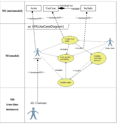
UML is defined by using a metamodeling approach where a metamodel was
used to specify the model that comprises UML elements (Object Management Group
(OMG), 2011b). As an example, in Figure 2.1, at layer M0, Ali is a real object or
run-time instances of Customer in M1, where M0 contains run-time instances of
model elements in M1. Customer and Order Clerk are actors and use cases
Create new order, Look up item availability, Validate
customer account and Update order in model layer (M1) are instances of
12
M2 (metamodel)
M1(model)
[image:34.595.118.522.67.501.2]M0 (run-time instances)
Figure 2.1: UML language architecture
In the following section, details of UML diagrams are discussed to get the
overview of the model.
2.2.1 UML model
A UML model may consist of different UML diagrams (Huzar, et al., 2005,
Shinkawa, 2006, Straeten, 2005). Currently, UML 2.4.1 specifies fourteen (14) UML
diagrams. They can be used to describe different views of a system. Structural view
is specified by structure diagrams such as profile diagram, class diagram, composite
structure diagram, component diagram, deployment diagram, object diagram and
package diagram, while behavioural view is specified by behaviour diagrams such as
Actor
Ali: Customer
UseCase Include
+includingCase +include
<<instanceOf>> <<instanceOf>>
<<instanceOf>>
13
activity diagram, sequence diagram, communication diagram, interaction overview
diagram, timing diagram, use case diagram and state machine diagram. Among the
diagrams, UML class diagram, use case diagram, sequence diagram and activity
diagrams are the most frequently used diagrams by the UML practitioners (Dobing &
Parsons, 2008, Grossman, et al., 2005). Each of the UML diagram is used to describe
various aspects of a system. For example, use case diagram is used to highlight main
functions of a system and roles that interact to it, while activity diagram is used to
model scenario of use cases in terms of dynamic aspect of a society of objects. On
the other hand, sequence diagram is modelled to show communication between
objects in term of sequence of messages, while the class diagram is to show the
classes of the objects in term of their attributes, methods and relationship to other
classes.
Furthermore, UML diagrams contain graphical representations of nodes and
paths. As an example, in Figure 2.1, use case diagram in layer M1 (model) is
depicted by the actor, use case and include graphic nodes. Each graphic node has its
notation; for example, notation for the actor is an icon of a stick man with its name.
The nodes and paths represent UML elements in the metamodel layer (M1). In the
metamodel layer, the UML modelling elements, their attributes, relationships, as well
as their rules and constraints are defined in UML standard (Object Management
Group (OMG), 2011b) in the form of abstract syntax. In the standard, each of the
UML elements in the abstract syntax is also given added descriptions as mention in
constraints, semantics and notations sections. The constraints of UML elements as
described in abstract syntax and constraints sections are well-formedness rules that
apply to the elements (Object Management Group (OMG), 2011b). They are
important to be satisfied within a single UML diagram as they impact the
completeness of the UML model (Christian F. J. Lange & Chaudron, 2004).
However, the constraints in constraint section in the UML standard are specified in
natural language and some of them are specified using Object Constraint Language
(OCL).
Therefore, in the following section, four (4) UML diagrams focused in this
research, namely UML use case diagram, activity diagram, sequence diagram and
class diagram are explained in terms of their functions, graphical nodes and paths,
14
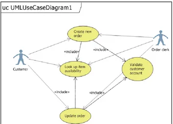
2.2.1.1Use case diagram
A use case diagram visualizes the main functions of a system and different roles that
interact with it. The system functions are represented by a set of use cases, while the
roles that interact to the system are represented by a set of actors. The use case
diagram may also contain associations between the actors and the use cases,
generalization among the use cases and actors, and relationship between use cases.
As an example of use case diagram is in Figure 2.2. In the figure, there are two (2)
actors, Customer and Order Clerk. Actor Customer has association
(communicate) with use cases named Create new order, Look up item
availability and Update order. While actor Order Clerk interacts with
Look up item availability and Update order. Based on Figure 2.2, it
is also shown that Create new order and Update Order use cases include
two (2) use cases Look up item availability and Validate
customer account.In this example, Create new order and Update
Order use cases are the including use cases, while Look up item
availability and Validate customer account are the included use
[image:36.595.142.496.474.728.2]cases.
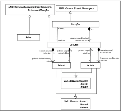
15
These graphical nodes for use case diagram adhere to UML elements and
their relationships as described by its abstract syntax are shown in Figure 2.3. This
research looks into Actor, UseCase and Include elements. Actor is a role played by a
user and other system that interact with the system to be built. An Actor must have a
name and can only have associations with UseCase and the association must be
binary. This also confirms that actors are not allowed to interact or associate with
other actors. Next, UseCase is a specification of a set of actions performed by the system. A UseCase must also have a name. It cannot have any association with other
use cases. It can only be involved in binary associations to Actor. A UseCase can also include other use cases. A source use case that includes other use cases is called
including use case, while the target use cases are called included use case. Include element is to show that the behaviour of the included use case is inserted to the
behaviour of the including use case. The including use case also cannot include itself.
Because Actor and UseCase elements itself do not state about the generalization between actors and between use cases, this constraint is stated in Classifier elements.
The Classifier is generalized by BehavioredClassifier element where Actor and UseCase are generalized to (as shown in Figure 2.3). In this thesis, the proposed formal specifications for the elements and their relationships are described in Chapter
16
Figure 2.3: Abstract syntax for UML use case diagram (Object Management Group (OMG), 2011b)
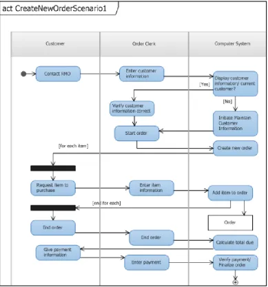
2.2.1.2Activity diagram
Activity diagram is used to model the workflow of use cases (Ericsson, 2004) . It is a
simply workflow diagram that describes the various user or system activities, the
person who does each activity and the sequential flow of these activities (Satzinger,
et al., 2005). It can be the same as flow chart and data flow diagramming in structured based software development. The diagram may consist of initial node,
activity state, activity partition, object flows, guard, fork, join and end-node. As
shown in an example of activity diagram with heading act
CreateNewOrderScenario1in Figure 2.4, there is an initial node and three (3)
activity partitions which are Customer, Order Clerk and Computer
System. There are sixteen (16) actions; among them Contact RMO, Enter
Classifier UML::Classes::Kernel::Namespace UseCase 0..1 * {subsets ownedMember} +ownedUseCase * +useCase
* +subject
Extend Include
{subsets source} 1 +includingCase
{sub sets ownedMember * +include
* {subsets target} 1 +addition
* {subsets target} 1 +extendedCase
* {subsets source} +extension 1
17
customer information, Display customer information and others.
[image:39.595.126.516.134.552.2]There is also one (1) object node; Order and one (1) activity final node.
Figure 2.4: Graphical nodes and paths in activity diagram
These graphic elements are categorized into three (3) categories; graphic
nodes, graphic paths and containment. Graphic nodes may consist of control nodes,
action nodes and object nodes. Example of action nodes and object nodes are as
explained in Figure 2.4, while control nodes consist of initial node, activity final
node, flow final node, decision node, join node, fork node and merge node. Graphic
path is the activity edges which contains of control flows and object flows.
Containment consists of a set of activities and activity partitions. There are twenty
18
(OMG), 2011b) used to show elements and their relationship adhering to those
graphical nodes and paths for activity diagram. Therefore, to simplify the figures,
only elements that are related to this research will be discussed in the thesis. This
research will look into Action, ObjectNode, ControlNode, ControlFlow, ObjectFlow,
Activity and ActivityPartition elements. An action (Action) is a single step within an activity (Activity), while an activity (Activity) represents a behaviour that is
composed of actions. An object node (ObjectNode) is an activity node that indicates
an instance of a particular classifier. It is used in showing the flow of objects. Paths
that link two (2) action nodes are called ControlFlow, while paths that link actions and object nodes are called ObjectFlow. Finally, an ActivityPartition is used to group
actions that have some characteristics in common. Formalization of UML elements
in activity diagram into logical specification as alternative description to the elements
are described in Chapter 4 in this thesis.
2.2.1.3Sequence diagram
In Unified Process (UP), sequence diagrams have the dependency to use case
diagram, activity diagram and class diagram (Satzinger, et al., 2005). Sequence
diagram focuses on interchange of messages between lifelines. A sequence diagram
may consist of frame, lifeline, execution specification, occurrence specification,
interaction use, combined fragment, state invariant, asynchronous message,
synchronous message, lost message, found message and others. For example,
sequence diagram in Figure 2.5 shows that it is in a frame with heading sd
CreateNewOrderScenario1. There are also two (2) lifelines; order clerk
and system, three (3) asynchronous messages; +startOrder(accountNo),
+addItem(catalogID, prodID, size, quantity)and
+completeOrder(paymentAmt), one (1) synchronous message;
+addItem(catalogID, prodID, size, quantity) and
description,price,extendedPrice and four (4) execution specifications
19
Figure 2.5: Graphical nodes and paths in a sequence diagram
There are eight (8) figures in UML Superstructure Specification used to
show the elements and their relationship adhering to the graphical nodes and paths
for sequence diagram (Object Management Group (OMG), 2011b). Straeten (2005)
20
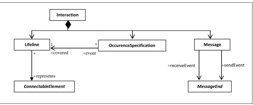
Figure 2.6: Fragment abstract syntax for UML sequence diagram (Object Management Group (OMG), 2011b)
Elements shown in the figure are restricted to elements that are used in this
research. This research will look into Interaction, Lifeline, Message and
ConnectableElement. In an Interaction, there is more than one Lifeline. A lifeline format is shown as Figure 2.7.
<lifelineident>::=([<connectable-element-name>[‘[‘<selector>’]’]][:<class_name>]
[decomposition])|‘self’<selector>::=<expression><decomposition>::=‘ref’<interactio nident> [‘strict’]
Figure 2.7: Lifeline format(Object Management Group (OMG), 2011b)
As shown in Figure 2.6, a Lifeline represents a ConnectableElement. It
reflects to lifeline format in Figure 2.7 where <connectable-element-name> is referring to the ConnectableElement. According UML Superstructure Specification,
<class_name> in Figure 2.7 refers to type referenced of ConnectableElement (Object
Management Group (OMG), 2011b). Hence, ConnectableElement can be defined as
a set of objects that are instance of set of classes (Straeten, 2005). A Message is a
communication between Lifeline. It associates normally to two
OccurenceSpecification, one for sending OccurenceSpecification and one for
receiving OccurenceSpecification. In this thesis, the proposed formal logical
specification for those UML elements in sequence diagram as alternative description
to the elements are described in Chapter 4. Lifeline
ConnectableElement
Interaction
*
+represents
OccurenceSpecification Message
* +event
s 1
+covered
MessageEnd
21
2.2.1.4Class diagram
From sequence diagrams, all types of the lifelines which are classes are gathered in a
class diagram. Class diagram is a collection of static modelling elements, such as
classes and their relationships. It is used to represent explicitly the information on a
domain of interest. The diagram may consist of classes and the association between
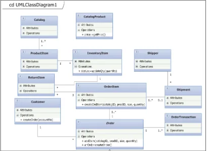
them. As shown in Figure 2.8, there are eleven (11) classes which are Catalog,
ProductItem, ReturnItem, Customer, CatalogProduct,
InventoryItem, OrderItem, Order, Shipper, Shipment and
OrderTransaction. There are also associations between those classes such as
between Catalog and ProductItem, ProductItem and InventoryItem,
[image:43.595.115.524.349.646.2]and others.
Figure 2.8: Graphical nodes in class diagram
In the UML Superstructure Specification, there are seventeen (17) figures
used to show elements and their relationship adhered to those graphical nodes and
22
simplified to one (1) figure (as shown in Figure 2.9) showing the significant elements
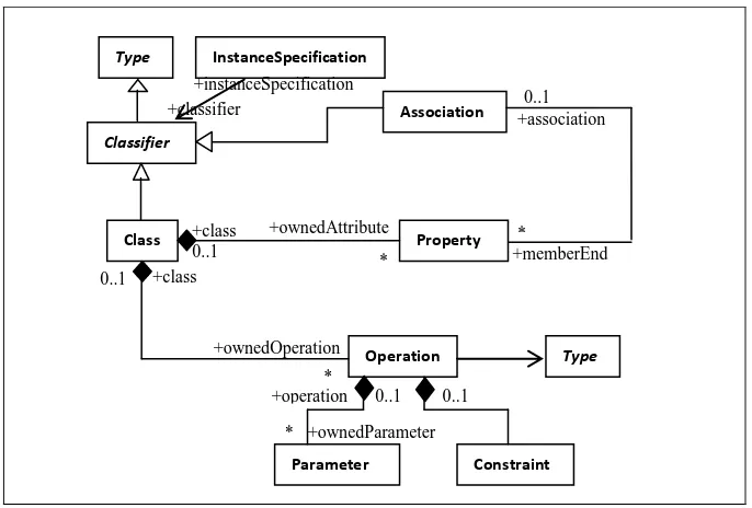
used in this thesis. This thesis will look into Class and Association elements. A Class
represents a set of objects. A Class is a kind of Classifier that has attributes
(ownedAttribute) and operations (ownedOperation). The attributes of a Class are
instances of Property. An Operation is a behavioural feature of a classifier that specifies name, type (Type), parameter (Parameter) and constraint (Constraint). The
formal logical specifications for the UML elements in class diagram are described in
[image:44.595.148.491.254.486.2]Chapter 4 of this thesis.
Figure 2.9: Abstract syntax for UML class diagram(Object Management Group (OMG), 2011b)
As described in this section, there are various diagrams with different views -
structural and behavioural - which are used to describe different aspects of a system,
with different notations and elements. On the other hand, the specification of
constraints of each of UML elements in abstract syntax, natural language and some
of them in OCL shows the lack of formal syntax and semantics in UML. These
features of UML itself are prone to have consistency problems or UML
inconsistencies between UML diagrams. Therefore, in the following section, details
of UML consistency are discussed. Class Classifier Type Property +class 0..1 +ownedAttribute * Operation +class +ownedOperation 0..1 * Association +memberEnd * +association 0..1 Type Constraint Parameter
23
2.3 UML consistency definition
Spanoudakis & Zisman (2001) define consistency as a state in which two or more
overlapping elements of different software models make assertion about the aspects
of the system they describe which are jointly satisfiable. While, Shinkawa (2006)
defines a set of UML model as consistent when there are no conflicts between two
arbitrary UML diagrams. On the other hand, a UML model is inconsistent when it
violates the constraints (Hubaux, et al., 2009, Sourrouille & Caplat, 2004,
Spanoudakis & Zisman, 2001). It is important to ensure that a UML model is
consistent as it is one of the attributes used in measuring the quality of a UML model
(Nugroho & Chaudron, 2008). UML consistency is classified into horizontal or
intra-model consistency, vertical or inter-intra-model consistency, syntactic consistency, and
semantic consistency (Elaasar & Briand, 2004, Huzar, et al., 2005, Lucas, et al.,
2009, Mens, et al., 2005b, Usman, et al., 2008). In horizontal or intra-model
consistency, consistency is validated at a same level of abstraction between different
UML diagrams, while in vertical or inter-model consistency, consistency of different
UML diagrams are validated at different level of abstraction (Huzar, et al., 2005).
Meanwhile, syntactic consistency confirming a UML diagram towards its abstract
syntax, while semantic consistency validating semantic compatibility of diagram’s
behaviour (Huzar, et al., 2005). Syntactical consistency includes the well-formedness
rules described as a constraint in UML Superstructure Specification (Object
Management Group (OMG), 2011b). Table 2.1 below shows Lucas et al. (2009)
[image:45.595.107.528.607.747.2]giving concrete example of each consistency.
Table 2.1: Concrete example of consistency problem classification (Lucas, et al., 2009)
Type of consistency Syntactic Semantic
Horizontal The class names used in the sequence diagram should appear in the associated class diagram
The events produced in a sequence diagram should not produce inconsistent states in the state diagrams of the objects which participate in the interaction
Vertical The methods definition of a class should be consistent in all abstraction levels in which these methods could be defined