Journal of Chemical and Pharmaceutical Research, 2014, 6(5):218-225
Research Article
CODEN(USA) : JCPRC5
ISSN : 0975-7384
High speed micromouse servo controller based on DSP and FPGA
Haoming Zhang, Yinghai Wang and Peh lian Soon
Department of Electrical and Information Engineering, Tongling University, Anhui Province, China
_____________________________________________________________________________________________
ABSTRACT
Micromouse is an intelligent walking robot using embedded technology, depending on sensors for navigation, which consists of the ability to collect and gather information of the complex “maze" after forward and backward searching without human inspection. The micromouse memory the information automatically and select the shortest path, use smart algorithm to reach destination quickly. Servo controller based on single-chip microcomputer can not meet micromouse system special requirements of high speed and high stability. Hardware and software of servo controller based on DSP and FPGA was discussed and realized, and experimental results are also presented.
Key words: micromouse; embedded technology; searching; DSP; FPGA
_____________________________________________________________________________________________
INTRODUCTION
Autonomous robot can be used in the future as to venture into dangerous area, or to perform critical tasks, instead of having a human life as stack. Autonomous robot will be a trend in the future. More and more autonomous robots were being applied in hospital, airport and factory[1-3]. Micromouse is an autonomous robot, which is completely autonomous that is able to find their way from a predetermined starting position to the central area of the maze unaided. The robot will need to keep track of where it is, discover walls as it explores, store the maze and detect whether it has reached the goal. After it reached the goal, the robot will typically perform additional searches of the maze until it has found an optimal route from the start to the center. Once the optimal route has been found, the robot will run that route in the shortest possible time[4-6].Micromouse maze is made up of 256 squares arranged in a 16x16 grid of cells, and set up the maze using a standardize wall which will be different in different events[5-12], for examples Singapore’s competition will be using the wall shown in Figure 1,where as Japan competition will be using the wall show in Figure 2.
Fig.1:Wall for Singapore competition maze Fig.2:Wall for Japan competition maze
speed and high stability. To ensure that this project can be completed, there exists two sections that must be done which is hardware and software. Micromouse design of the analog circuits and as well as the digital circuits based on dual core DSP and FPGA is discussed (as shown figure 3).
Fig.3: Top view of the Micromouse
Although there is a lot research has to be done, the author willing to spend all time so that the performance of the robot fully satisfactory. Shining Sunshines Global PTE LTD co-operate with the author to complete this project. The objectives of this project are listed below:
1) To build and assemble an autonomous robot.
2) To learn, design and troubleshoot the analog/digital circuits design based on DSP+FPGA.
HIGH SPEED MICROMOUSE INTELLIGENT SERVO SYSTEM
In this paper, in order to overcome micromouse based on a single chip can not meet the stability and high speed requirements, abandon the domestic micromouse’s single chip operating mode, refer to foreign advanced design ideas, micromouse based on dual core DSP and FPGA was designed, intelligent servo system of the micromouse searching and tracing maze principle as shown in Figure 4.
Fig.4: Principle of smart micromouse servo controller
Micromouse intelligent servo system mainly includes: switch signal input unit, motor driving unit, maze information judgment and storage unit, searching and back-searching optimization unit, dashing and higher dashing optimization unit, and fault detection and protection etc.. This management system take FPGA(A3P250) as the core, realize synchronous servo control of two axis DC motor, free the DSP from the complex work, only handle sensor signal logic ,a part of the intelligent algorithm and the control of FPGA.
HARDWARE
Hardware circuit of the servo system mainly includes: switching circuit, power supply circuit, the motor and its drive circuit, quadrature encoder circuit, infrared sensor circuit etc.
SWITCH CIRCUIT
______________________________________________________________________________
74VC14 then were input to DSP(TMS320F2812), respectively, Their circuit principles are similar, one specific circuit principle of start as shown in figure 5.
UPC2 0.1uF UPR2 100K UPR5 2K DGND +3.3V 1A 1 1Y 2 2A 3 2Y 4 3A 5 3Y 6 GND 7 4Y 8 4A 9 5Y 10 5A 11 6Y 12 6A 13 VCC 14 74LVC14 +3.3V 7414P9 7414P9 DGND START_IN
Fig.5: Switch circuit
POWER CIRCUIT
In this system, micromouse is powered by rechargeable lithium-ion battery, the average voltage of the system is 11.1V, and the highest voltage is up to 12.6V. In order to meet the requirement of dual core controller, the DC bus voltage through step-down voltage chip L5973D, then the voltage is reduced to 5V, 5V voltage is changed to 3.3V to meet DSP and FPGA requirement, where 5V power supply circuit as shown in figure 6.
OUT 1 SYNC 2 INH 3 COMP 4 FB 5 VREF 6 GND 7 VCC 8 U680 L5973D L201 100uH ESID R3001 4.7K C3001 220pF C4001 22nF GND G N D +5V GND GND +12V U680P5
Fig.6: Power circuit
MOTOR AND ITS DRIVE CIRCUIT
DC motors convert electrical energy into mechanical energy. DC brushed motors contain internal brushes for commutation. They have a positive terminal and a negative terminal through which external power is supplied. They are usually fitted with encoders for closed-loop position feedback.
DC motor speed control has excellent characteristics, such as speed can be changed smoothly, speed adjustment range is wide, DC motor can realize a frequent quick starting and braking, and overload capacity is strong, these characteristics can meet fast dashing micromouse special requirements in a complex maze. DC motor (T006SR+IE2-512) is used in the system. Its parameters as shown in table 1.
Table1. Parameters of motor
Voltage 6 V Weight 35 g Power 4 W Diameter 22 ±0.5 mm Efficiency 85 % Length 24±0.5 mm Speed 7500 rpm Shaft diameter 2 ±0.1 mm Torque 10 mNm Encoder 512 lines
Pulse width modulation (PWM) is a technique to control the analog circuits with a processor’s digital output, this project will be using the FPGA to generate the output instead of microcontroller. PWM can be seen as a way of digitally encoding analog signal levels .By using a high resolution counters, the duty cycle of a square wave is modulated so that it will encode a specific analog signal level on it. The PWM signal is in the form of digital pulse as the full DC supply is either totally on or off at any given instant of time. DC supply will be applied to the load during the on-time and switched off in the off-time. It can also be treated as a person in charge control the power supply by deciding the actual on time for the motor to rotate, so by turning on and off, the motor will rotate at different speed. Advantage of using PWM is that the power loss in the switching devices is very low.
1 1 2 2 3 3 4 4 5 5 6 6 7 7 8 8 9 9 10 10 11 11 12 12 13 13 14 14 15 15 16 16 17 17 18 18 19 19 20 20 21 21 22 22 23 23 24 24 L6207 L6207 47ohms XIN1R 47ohms XIN2R 47ohms YIN1R 47ohms YIN2R 1 0 0 o h m Y E N 1 R 1 0 0 o h m X E N 1 R 5 .6 n F C C 1 5 .6 n F C C 2 G N D G D N XIN1 XIN2 YIN1 YIN2 X E N 1 Y E N 1 AVREF VCP XOUT2 +24V GND GND +24V YOUT2 VBOOT AVREF SENSEAP3 RCA XOUT1 GND GND YOUT1 RCB SENSEBP10
Fig.7: Motor drive circuit based on L6207D
In the above circuit, XIN1, XIN2, YIN1, YIN2 represents motor X and motor Y PWM positive and negative signal respectively, generated by FPGA (A3P250) according to the parameters transferred by DSP, from the method, PWM signal of DC motor speed regulation is realized by hardware circuit, which improves the micromouse’s handling date ability greatly.
QUADRATURE ENCODER
An rotary encoder is an electromechanical device that can be used to measure the motion or position of a device by converting the angular position or motion of a shaft to an analog or digital code. An incremental rotary encoder are widely used in industrial controls, robotics, computer input devices such as micromouse.
An incremental rotary encoder will be used in this project. It has two outputs which are normally known as Channel A and Channel B in this project and the quadrature outputs can be either mechanical or optical. Figure 8 shows the components which are needed for the optical encoder. The disk is mounted on the rotating shaft and has patterns of opaque and transparent sectors coded into the disk. The theory behind is that while the disk is rotating, the opaque segments block the light and the light only pass through when the glass is clear and thus generate a square-wave pulses.
Fig.8: Optical encoder components
Instead of using only one set of pulses, it could not indicate the direction of rotation, so by adding in another set of pulses which positioned 900out of phase with the previous pulses (Figure 9) now the two outputs channels indicate
______________________________________________________________________________
Fig.9: Quadrature encoder output Channel A and Channel B
INFRARED SENSOR CIRCUIT
Infrared sensor is an electronic device that emits infrared radiation and by detecting the reflection of the radiation through the receiver. Infrared sensors are easy to design and assemble because the components required are easy to come by [13-16].
The placement of the transmitter and receiver of the infrared sensor for the micromouse is shown in the figure below.
Fig.10: Placement of infrared sensor
The red color arrows show the infrared radiation and after it hit the wall, it will reflect back to the receiver. By measuring the voltage produced by the receiver, the distance between the sensors can be approximated. By placing a resistor between the power supply and the infrared emitter can manipulate the intensity of the emitter so that the receiver would not get saturated easily by detecting large amount of infrared radiation.
The robot has 6 pairs of infrared transmitters and receivers, so that it can detect the walls. Its principle is shown in figure.11.
Fig.11: Infrared sensor transmitting and receiving circuit
In the circuit, SFH4550 emits the infrared light, change the value of R16 can change the intensity of the reflected light,TSL262 accepts the reflected infrared light and convert it, then input the value to MCU.
SOFTWARE
arithmetic logic unit, which increases its powerful digital signal processing ability. In addition, large capacity RAM are integrated into the chip, which can greatly simplify servo system circuit design, reduce system cost and complexity, but also greatly improve the storage capacity of data processing.
Field programmable gate array (FPGA) is just based on the standard unit array, it does not have a general integrated circuit function, but according to different needs, the user through a software can change its internal connectivity, in a relatively short period of time can realize specific integrated circuit function, and can secondary develop and change the software, so as to reduce the cost and shorten the cycle of product development. Due to the design of FPGA circuit uses traditional software ideas, which makes system design based on FPGA has a good reusability and modification, and greatly improved the calculation speed of the system. The new design concept just meets the high performance multi axis servor control system requirements, so in this paper micromouse intelligent servo system chooses TMS320F2812 and A3P250 as the core, PWM control signal of two axis motors completed generated by A3P250.
According to the requirements of the system, principle of dual core intelligent servo system based on DSP and FPGA was shown in Figure 12.
Battery handling Begin
NO
state of battery System initialization
searching
Maze optimization Destination?
Back to start
dashing
return
NO NO
Fig.12: Flow chart of smart management system software
EXPERIMENT SECTION
The experimental micromouse prototype is shown in figure 13.
Fig.13: Micromouse prototype
______________________________________________________________________________
Fig.14: Simulation results-ChA leads ChB
The PWM output from A3P250 as shown in figure 15, as can be seen, pulse of PWM output waveform from the FPGA is very small, and the duty ratio of PWM signal is constant, which reduces interference to drive circuit.
Fig.15: PWM waveform from FPGA
PWM signal to drive the X axis DC motor and Y axis DC motor in straight as shown in figure 16, as can be seen from the figure, the two DC motor PWM wave duty ratio is almost equal, which ensures that the two DC motor can walk at the same speed, ensures the accuracy of micromouse in straight navigation.
Fig.16: Input PWM waveform of motor
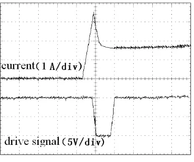
Increase the discharging current rapidly. The discharge current and discharge MOSFET gate drive signal as shown in figure 18.
Fig.18: Current experiment
From the test waveform can be seen, when sampling current is too high exceed the limitation, MOSFET is shut off immediately, when sampling current recovery to the normal set value, MOSFET is automatically opened, which shows that current sampling circuit and protection circuit can work right, can effective protect of the test device and the system.
CONCLUSION
To meet the special requirements of high speed micromouse maze tracing, dual core micromouse based on DSP and FPGA is proposed. Intelligent servo system hardware and software is discussed and realized. Experiment result of motors show that the designed intelligent servo system can effectively realize two axis motor synchronous controls; Overcurrent test has proved that the system can effectively protect the power system.
Acknowledgement
It is a project supported by basic research programs of Suzhou science and Technology Department - industrial application part (SYG201327) and 2012 Innovation Project of JiangSu Province.
REFERENCES
[1]Q. Zhang, M. Li, X. S. Wang, Y. Zhang, Journal of Computers, vol.7, no.3, pp. 657-662, March 2012. [2]L.F. Zhou and J. Jiang, Journal of Computers, vol.7, no.2, pp. 405-410, February 2002.
[3]Kiblcr S G,Ilauer A E, Giesscl D S, etc, “IEEE Micromouse for mechatronics research and education” ,
Mechalronics (1CM), 2011 IEEE International Conference: 887-892.
[4]Po-Jen Cheng,Chin-Hsing Cheng,Chun-Cheng Tung, Journal of Information and Optimization Sciences,
2009,Vol.30(6):1197-1207.
[5]Zhang Haoming, PEH lian Soon,Wang Yinghai, Applied Mechanics and Materials Vols. 496-500:1674-1680. [6]Zhang Haoming, PEH lian Soon,Wang Yinghai, Applied Mechanics and Materials Vols. 496-500:1664-1669. [7]Jiang Xiong,Ren Hua-long,Ma Zhong-li, Modern Electronics Technique , 2011(08):14-16.
[8]TONDR A D, HALL Drew. “The inception of chedda: a detailed design and analysis of micromouse”, Las Vegas:
University o f Nevada, 2004.
[9]Zhou Yi-min, Fu Jun-hua, Microcomputer Information , 2010(13):25-29.
[10]Fu Xiu-wei, Zhang Hua, Journal of Jilin Institute of Chemical Technology, 2012(01):47-49
[11]Wen Ru-chun, Xu Ying, Wang Zu-lin, Journal of Jiangxi University of Science and Technology ,
2010(02):26-28.
[12]He Shao-Bo, Sun Ke-Hui, Computer Systems & Applications , 2012(09):79-82. [13]Chen Yu, Yang Ji-min, Modern Electronics Technique , 2011(10):68-70. [14]Bo En, Yu yuanyuan, Value Engineering , 2011(20):136-137.