i
HARMONIC REDUCTION OF A SINGLE-PHASE
MULTILEVEL INVERTER USING GENETIC ALGORITHM
AND PARTICLE SWARM OPTIMIZATION
LING CHIN WAN
HARMONIC REDUCTION OF A SINGLE-PHASE MULTILEVEL INVERTER USING GENETIC ALGORITHM AND PARTICLE SWARM OPTIMIZATION
LING CHIN WAN
A thesis submitted in
partial fulfilment of the requirements for the award of the Degree of Master of Electrical Engineering
Faculty of Electrical and Electronic Engineering Universiti Tun Hussein Onn Malaysia
iii
iv
ACKNOWLEDGEMENT
I would like to express my heartily gratitude to my supervisor, Associate Professor Ir Dr Goh Hui Hwang for all the idea, guidance, motivation and support that he had given to me throughout the years of his supervision. Without his guidance and inspiration, this research could not be successfully completed.
Also, my gratitude is devoted to all my friends and to those whom involve directly or indirectly with this research for their co-operation, help and encouragement in the effort to succeed my research.
Besides that, 1 would like to thanks the Ministry of Science, Technology and Innovation, Malaysia (MOSTI) and the Office for Research, Innovation, Commercialization, Consultancy Management (ORICC), Universiti Tun Hussien Onn Malaysia (UTHM) for financially supporting this research FRGS voted 1521 and Science Fund N0.S023. I would like to thanks also the Ministry of Education Malaysia for the MyBrain 15 scholarships provided, which enable me to complete my study.
v
ABSTRACT
Inverter play important role in power system especially with it capability on reducing system size and increase efficient. Recent research trend of power electronics system are focusing on multilevel inverter topic in optimization on voltage output, reduce total harmonics distortion, modulation technique and switching configuration. Standalone application multilevel inverter is high focused due to the rise of renewable energy policy all around the world. Hence, this research emphasis on identify best topology of multilevel inverter and optimize it among the diode-clamped, capacitor clamped and cascaded H-bridge multilevel inverter to be used for standalone application in term of total harmonics distortion and voltage boosting capability. The first part of research that is identify best topology multilevel inverter is applying sinusoidal pulse width modulation technique. The result shown cascade H-bridge give the best output in both total harmonics distortion (9.27%) and fundamental component voltage (240 Vrms).
vi
ABSTRAK
Inverter memainkan peranan penting dalam sistem kuasa terutamanya dengan keupayaan mengurangkan saiz sistem dan meningkatkan efisien. Kajian terhadap elektronik kuasa sistem amat giat dalam kategori optimisme kualiti voltan output, mengurangkan jumlah herotan harmonik, teknik modulasi dan konfigurasi suis. Aplikasi inverter berdikari difokuskan dengan galakan penggunaan tenaga boleh diperbaharui di seluruh dunia. Oleh itu, kajian ini fokus kepada mengenal pasti konfigurasi suis inverter yang paling sesuai untuk aplikasi inverter berdikari dari diode clamped, capacitor clamped dan cascaded H-bridge inverter bertingkap. Kajian mula dengan simulasi ketiga tiga inverter dengan mengaplikasi teknik sinusodal pusle width modulation. Keputusan menujukan bahawa cascaded H-bridge inverter merupakan terbaik berbanding dengan yang lain dengan jumlah herotan harmonik (9.27%) dan frekuensi asas komponen voltan (240 Vrms). Kajian diteruskan dengan optimisme
cascaded H-bridge inverter dengan teknik optimized harmonic stepped waveform
CONTENTS
TITLE i
DECLARATION ii
DEDICATION iii
ACKNOWLEDGEMENT iv
ABSTRACT vi
ABSTRAK ivii
CONTENTS vii
LIST OF TABLES viii
LIST OF FIGURES viii
LIST OF ABBREVIATIONS AND SYMBOLS xxiii
CHAPTER 1 INTRODUCTION
1.1 Project background 1
1.2 Problem statement 3
1.3 Aim and objectives 4
1.4 Research scopes 4
1.5 Thesis outline 5
ii
2.1 Power electronic system 6
2.2 Power converter 8
2.3 Voltage source inverter 10
2.4 Multilevel inverter 12
2.4.1 Diode-Clamped Multilevel Inverter 13
2.4.2 Capacitor-Clamped Multilevel Inverter 15
2.4.3 Cascaded H-Bridge Multilevel Inverter 17
2.5 Total harmonic distortion 19
2.6 Modulation techqniue 20
2.6.1 Carrier-based pulse width modulation 21
2.6.2 Third harmonics injection pulse width
modulation method. 22
2.6.3 Space vector pulse width modulation 22
2.6.4 Harmonics Based Optimized harmonics
stepped waveform modulation 22
2.7 Selective harmonics elimination 23
2.8 Previous research work on multilevel inverter 24
CHAPTER 3 METHODOLOGY
3.1 Proposed multilevel inverter 26
3.1.1 Multilevel topologies involved 29
3.1.2 Sinusiodal pulse width modulation 31
3.1.3 Simulation parameter 32
3.2 Multilevel inverter optimization 33
3.2.1 Optimized harmonics stepped waveform
iii
3.2.2 Fourier series approach voltage output 35
3.2.3 Selective harmonics elimination calculation
40
3.3 Bio-inspired algorithm 42
3.3.1 Genetic algorithm 42
3.3.1 Particle Swarm optimization algorithm 47
CHAPTER 4 RESULTS AND DISCUSSION
4.1 Topologies comparison 49
4.1.1 3-level multilevel inverter 49
4.1.2 5-level multilevel inverter 53
4.1.3 7-level multilevel inverter 55
4.2 Multilevel inverter optimization 58
4.3 Switching signal comparisons 58
4.4 Optimized harmonics stepped waveform (Genetic
algorithm) 59
4.4.1 3-level with equal DC sources 59
4.4.2 5-level with equal DC sources 63
4.4.3 7-level with equal DC sources 68
4.4.4 3-level with unequal DC sources 71
4.4.5 5-level with unequal DC sources 75
4.4.6 7-level with unequal DC sources 79
4.5 Optimized harmonics stepped waveform (Particle
swarm optimization) 84
4.5.1 3-level with equal DC sources 84
iv
4.5.3 7-level with equal DC sources 93
4.5.4 3-level with unequal DC sources 97
4.5.5 5-level with unequal DC sources 101
4.5.6 7-level with unequal DC sources 105
4.6 Overall discussion 109
CHAPTER 5 CONCLUSION
5.1 Conclusion 114
5.2 Research contribution 115
5.3 Future work and recomendation 116
PUBLICATIONS 117
REFERENCES 118
APPENDIX A 126
APPENDIX B 129
v
LIST OF TABLES
2.1 3-level diode clamped multilevel inverter switching configuration 15
2.2 3-level capacitor clamped multilevel inverter switching configuration
17
2.3 Components comparison of multilevel inverter topologies 19
2.4 Literature on multilevel inverters 25
3.1 Simulation parameter 27
3.1 Particle swarm optimization parameter 47
4.1 3-level multilevel inverter analysis 53
4.2 5-level multilevel inverter analysis 56
4.3 7-level multilevel inverter analysis 58
4.4 3-level switching angles 60
4.5 3-level total harmonics distortion with respective modulation index 62
4.6 5-level switching angles 64
4.7 5-level total harmonics distortion with respective modulation index 66
4.8 7-level switching angles 68
4.9 7-level total harmonics distortion with respective modulation index 70
vi
4.11 3-level total harmonics distortion with respective modulation
index (unequal) 74
4.12 5-level switching angles (unequal) 76
4.13 5-level total harmonics distortion with respective modulation
index (unequal) 78
4.14 7-level switching angles (unequal) 80
4.15 7-level total harmonics distortion with respective modulation
index (unequal) 82
4.16 3-level switching angles 85
4.17 3-level total harmonics distortion with respective modulation index 87
4.18 5-level switching angles 89
4.19 5-level total harmonics distortion with respective modulation index 92
4.20 7-level switching angles 94
4.21 7-level total harmonics distortion with respective modulation index 96
4.22 3-level switching angles (unequal) 98
4.23 3-level total harmonics distortion with respective modulation
index (unequal) 100
4.24 5-level switching angles (unequal) 102
4.25 5-level total harmonics distortion with respective modulation
index (unequal) 104
4.26 7-level switching angles (unequal) 106
vii
index (unequal) 108
4.28 Comparison of multilevel inverter on total harmonic distortion 111
4.29 Comparison of fundamental frequency voltage 112
4.30 Comparison between SPWM and OSHW method 112
4.31 Comparison between equal and unequal DC sources (Genetic
algorithm) 113
4.32 Comparison between equal and unequal DC sources (Particle swarm
viii
LIST OF FIGURES
2.1 Illustrated square wave signal 9
2.2 Illustrated modified square wave signal 9
2.3 Illustrated pure sine wave signal 10
2.4 Voltage source inverter family 11
2.5 3-level diode clamped multilevel inverter topology 14
2.6 3-level capacitor clamped multilevel inverter topology 16
2.7 2-level cascaded H-bridge multilevel inverter topology 18
2.8 Classification of multilevel inverter modulation method 21
3.1 General block diagram of inverter system 27
3.2 Overall work flow chart 28
3.3 3-level capacitor clamped multilevel inverter topology 29
3.4 3-level diode clamped multilevel inverter topology 30
3.5 3-level Cascade H-bridge multilevel inverter 30
3.6 SPWM phase disposition modulation 31
3.7 Comparison of modulation signal and carrier signal illustration 32
3.8 3-level optimized harmonics stepped waveform topology 34
ix
3.10 Generalized staircase waveform of 5-level multilevel inverter 36
3.11 6 level quarter-wave symmetric waveform 38
3.12 Flow chart of genetic algorithm 43
3.13 Matlab constraint M-file 44
3.14 Matlab fitness M-file 45
3.15 Matlab optimization tool (Genetic Algorithm) 46
3.16 Particle swarm optimization flow chart 48
4.1 3-level cascaded H-bridge multilevel inverter system 50
4.2 Voltage output 3-level CC-MLI 50
4.3 Voltage output 3-level DC-MLI 51
4.4 Voltage output 3-level CHB-MLI 51
4.5 FFT analysis of 3-level CC-MLI output 52
4.6 FFT analysis of 3-level DC-MLI output 52
4.7 FFT analysis of 3-level CHB-MLI output 52
4.8 5-level cascaded H-bridge multilevel inverter system 53
4.9 FFT analysis of 5-level CC-MLI output 54
4.11 FFT analysis of 5-level DC-MLI output 54
4.12 FFT analysis of 5-level CHB-MLI output 55
4.12 7-level cascaded H-bridge multilevel inverter system 56
4.13 FFT analysis of 7-level CC-MLI output 56
4.14 FFT analysis of 7-level DC-MLI output 57
x
4.16 Switching signal of SPWM (a) and OHSW (b) 59
4.17 3-level switching angle versus modulation index 61
4.18 3-level fitness function value versus modulation index 62
4.19 Voltage output 3-level (m=0.85) 63
4.20 FFT analysis of 3-level output (m=0.85) 64
4.21 5-level switching angle versus modulation index 65
4.22 5-level fitness function value versus modulation index 65
4.23 Voltage output 5-level (m=0.8) 67
4.24 FFT analysis of 5-level output (m=0.8) 67
4.25 7-level switching angle versus modulation index 69
4.26 7-level fitness function value versus modulation index 69
4.27 Voltage output 7-level (m=0.8) 71
4.28 FFT analysis of 3-level output (m=0.8) 71
4.29 3-level switching angle versus modulation index (unequal) 73
4.30 3-level fitness function value versus modulation index (unequal) 73
4.31 Voltage output 3-level unequal DC (m=0.85) 75
4.32 FFT analysis of 3-level unequal DC output (m=0.85) 75
4.33 5-level switching angle versus modulation index (unequal) 77
4.34 5-level fitness function value versus modulation index (unequal) 77
4.35 Voltage output 5-level unequal DC (m=0.80) 79
4.36 FFT analysis of 5-level unequal DC output (m=0.80) 79
xi
4.38 7-level fitness function value versus modulation index (unequal) 81
4.39 Voltage output 7-level unequal DC (m=0.80) 83
4.40 FFT analysis of 7-level unequal DC output (m=0.80) 83
4.41 3-level switching angle versus modulation index 86
4.42 3-level fitness function value versus modulation index 86
4.43 Voltage output 3-level (m=0.85) 88
4.44 FFT analysis of 3-level output (m=0.85) 88
4.45 5-level switching angle versus modulation index 90
4.46 5-level fitness function value versus modulation index 91
4.47 Voltage output 5-level (m=0.8) 93
4.48 FFT analysis of 5-level output (m=0.8) 93
4.49 7-level switching angle versus modulation index 95
4.50 7-level fitness function value versus modulation index 95
4.51 Voltage output 7-level (m=0.8) 97
4.52 FFT analysis of 3-level output (m=0.8) 97
4.53 3-level switching angle versus modulation index (unequal) 99
4.54 3-level fitness function value versus modulation index (unequal) 99
4.55 Voltage output 3-level unequal DC (m=0.85) 101
4.56 FFT analysis of 3-level unequal DC output (m=0.85) 101
4.57 5-level switching angle versus modulation index (unequal) 103
4.58 5-level fitness function value versus modulation index (unequal) 103
xii
4.60 FFT analysis of 5-level unequal DC output (m=0.80) 105
4.61 7-level switching angle versus modulation index (unequal) 107
4.62 7-level fitness function value versus modulation index (unequal) 108
4.63 Voltage output 7-level unequal DC (m=0.80) 109
4.64 FFT analysis of 7-level unequal DC output (m=0.80) 110
4.65 Overall harmonic elimination for equal and no equal DC source
(Genetic Algorithm) 114
4.66 Overall harmonic elimination for equal and no equal DC source
xiii
LIST OF SYMBOLS AND ABBREVIATIONS
𝐴𝐴𝑐𝑐 Carrier amplitude
𝐴𝐴𝑚𝑚 Modulation amplitude
fval Fitness function value
𝑚𝑚 Number of voltage level
Pbest Best fitness (PSO)
Gbest Global best (PSO)
V Voltage
Hz Frequency
AC - Alternate current
CC-MLI - Capacitor clamped multilevel inverter
CHB-MLI - Cascaded H-bridge multilevel inverter
CSI Current source inverter
DC Direct current
DC-MLI - Diode clamped multilevel inverter
DG Distribution generation
GA Genetic algorithm
IGBT Insulated-gate bipolar transistor
MG Microgrid
MOSFET Metal–oxide–semiconductor field-effect transistor
PD Phase disposition modulation
xiv
PS Phase shift modulation
PWM - Pulse width modulation
OHSW Optimize harmonic stepped waveform
SPWM - Sinusoidal Pulse Width modulation
SHE Selective harmonic elimination
THD - Total harmonic distortion
1
CHAPTER 1
INTRODUCTION
1.1 Project background
In conjunction with industrialization and increase of human population, resultant
world energy demand continues to increase year by year. The population and energy
consumption is increasing correspondingly with time which is also predicted to
continue increasing in future [1]. This cause increasing demand of energy for future
energy sustain [1]. The exploration in renewable energy show increasing trend in past
decade. Examples of renewable energy sources (RES) such as sun, wind, geothermal,
biomass which will not be exhausted. RES have advantage over traditional sources in
less emission [2]. However, RES mostly experience problem related to inconsistent
output. For example, solar energy are dependent source which differ by radiation and
yet need to be covert form DC to AC. Renewable energy is always complemented with
inverter which hold the key to generating high efficient and reliable power. To utilize
2
Inverter can be classified into two main types that is voltage source inverter
(VSI) and current source inverter (CSI). Each types have their own unique characterise
which been listed in literatures [3-7]. From the literatures, a brief conclusion of VSI is
more popular than CSI can be make [3]. In addition, VSI transformer-less inverter
popular in renewable energy application due to overall size reduction. The most
common use inverter is high power 2-level PWM inverter. However high power
application ideally is require low switching losses.
In past decade, numberless of literature has proven multilevel inverter is a
practical solution on resolving high switching losses problem exist in conventional
inverter for high power application [8]. Research trend nowadays are more focusing
on several multilevel inverter topologies for renewable energy sources application.
Multilevel topologies inverter generate multilevel voltage source output which
synthesize the staircase waveform form single or multiple low DC voltage source. The
low input voltage source reduce the stress encounter by the switches with ability
produce high output voltage source. Currently, cascaded H-bridge multilevel inverter
(CHB-MLI) and it modified topologies is high grab attention due to the flexibility
toward renewable energy.
Multilevel inverter system can be separate into two sector which is inverter
topology system and switching strategy. Inverter topology system consist of the most
part include switches power sources, topology configuration and filter system.
Power source are mostly RE such as solar panel and wind turbine. For topology
configuration, there are 3 main type which been frequently cited in literature that is
diode clamped multilevel inverter (DC-MLI), capacitor clamped multilevel inverter
(CC-MLI) and cascaded H-bridge multilevel inverter (CHB-MLI) [9-16]. Filter part is
apply to remove harmonics and smoothen the inverter output quality.
The move on to next part that is switching strategy. This part manipulated the
harmonics profile for the inverter output waveform. The conventional type are square
wave. This type evolve into quasi-square wave which give better profile as compare
3
apply in currently VSI devices [17]. However, researcher explored other method on
overcome the cons of PWM where different kind of add on method been apply in
conjunction with PWM such as elective harmonic elimination (SHE). SHE consist of
complex non-linear equation on resolving best switching timing. Hence, various
calculation approach been tested to optimize the overall performance. The calculation
method include newton-rapshon, Fourier transform, and even bio-inspired algorithm
approach such as bee, ant, particle swarm, genetic, bat and others [18-23].
Multilevel inverter widely apply in power system area. The some of the power
generated by renewable resources are capable on self-sustainable for the user or even
excessive power can revert back to main grid. Hence, this research focus on the trend
of self-sustainable type or so call standalone application.
1.2 Problem statement
At present, existing high power system using traditional multi-pulse converter which
alone with bulky transform and filter system [24, 25]. The size of converter have given
a limitation to the application of converter especially in small scale usage such as
standalone application system. Beside of the sizing problem, traditional converter also
have high switching loss and electromagnetic interference (EMI) problem according
to the previous researches [26, 27]. In order to solve this problem, converter with
smaller size and low switching loss criteria is needed. However in standalone system
need to maintain or even performance better in term of harmonic distortions and
voltage boosting capability. Hence, inverter are found to be the solution.
Inverter play important role in regaining quality AC current to the consumer.
Multilevel inverter have been done individually research according to the literatures
for capacitor clamped [28, 29], diode clamped [30], cascaded H-bridge [31] and other
topologies [32-34]. Each research show the related topology to be suitable for
4
Among the topologies comparison, modulation strategies also hot topic of
research in inverter fields. Several literature found to be having difficulty in resolving
high non-linear equation of getting best switching timing [35-39]. The mathematical
approach have reach a limit in increasing calculation speed of the complex equation.
Due to all the problem mention in this section, the proposed solution will be presented
in next section.
1.3 Aim and objectives
The aim of this research is to analyse the performance of multilevel inverter topologies
for a standalone application. Hence following objectives had been listed to ensure
objective achieved.
a) To compare the performance of multilevel inverter topologies with sinusoidal
pulse width modulation in term of total harmonics distortion and the voltage
boosting capability.
b) Apply proposed switching method to optimize the multilevel inverter with
purpose to reduce total harmonic distortion and switching frequency.
c) To compare the capability of inverter system in adapting to balanced and
unbalanced voltage sources with different bio-inspired algorithm for switching
angle calculation.
1.4 Research scopes
Multilevel inverters are basically classified into three main categories which are
capacitor clamped multilevel inverter, diode clamped multilevel inverter and cascaded
H-bridge multilevel inverter. This research objective is to identify the most suitable
topology in a single phase standalone application. The three topologies are the
fundamental idea of the other latest modified topology. Hence, the scope has been
5
In simulation environment, topology construction and algorithm calculation is
realised with the aid of Matlab/Simulink software. The overall specification for the
simulation are listed as below. Total voltage input will always be 240 V, output voltage
modulated to 50 Hz and the sampling time is 1 ×𝑒𝑒−06s. MOSEF switches model is
used. Hence, Matlab R2015a is used throughout the research with the aid of other
software such as Microsoft Excel.
For the optimization of selected topology, optimized harmonic stepped
waveform is proposed to be applied. The simulation input remain total 240 V and the
sampling time is 1 ×𝑒𝑒−06s. The calculation of selective harmonics elimination in this
research is focus on comparison on genetic algorithm and particle swarm optimization.
Both method under same simulation model with them own specification mention in
methodology respectively.
In addition, three levels of multilevel inverter are applied in the research that
is 3-level, 5-level and 7-level multilevel inverter. In this research, main key point is
total harmonic distortion (THD), switching frequency, voltage boosting capability and
the capability in adapting unequal sources.
1.5 Thesis outline
The thesis is doing performances analysis of multilevel inverter for standalone
application. The literature studies of the project stated in chapter 2. Chapter 3 is the
methodology of simulation topology and modulation method are discussed. Chapter 4
is where the result and analysis of the simulation are presented. Lastly chapter 5 is the
6
CHAPTER 2
LITERATURE REVIEW
2.1 Power electronic system
In current decade, power electronics is been focused by researchers in several
industrial fields such as renewable energy, energy conversion, electrical vehicles and
storage system. Power electronic is a system with aim to perform efficient energy
condition, conversion and control form certain sources to a desired output condition.
This technology is a combination of electrical and electronics component with goal in
achieving high efficient, high availability, high reliability, small size, light weight and
low cost [40]. Power conversion is one of the main key on power electronics. Hence,
power electronic equipment can be classify into four main type that is AC to AC
conversion, DC to AC conversion, AC to DC conversion and DC to DC conversion
7
Power electronic device with rectifiers is been introduce in 1890 by
Dobrowlsky. However, the evolution invention in semiconductor which overcome the
short of rectifiers had urged evolution for power electronics fields. In the last of 1950s,
semiconductor industry invention, thyistor had widely introduce in power electronics
fields. Thyristor is introduced in 1957s by General Electric [41] which give a lot of
contribution in the early development of power electronic system. The literature shown
that thyristor type inverter had been replaced by other devices that is MOSFET, GTO
and IGBT afterward which is the current basic component of power electronics devices.
Inverter had been classify into current source and voltage source inverter. VSI
is more popular in the market due to aspect of cost, size and efficacy. A general power
electronic system for electrical generation purpose consist of distributed generation
(DG) resources, storages system, distribution system and communication and control
system. DG resources are technologies of combination of microsources and other
conventional sources. Microsource include renewable energy such as wind, solar, fuel
cell, biomass, geothermal and others. Conventional sources such as micro-hydro
power and diesel also can be implemented into MG generation resources [42, 43].
However, each source has different power generation method and criterias which affect
the power harvesting method [44].
Due to the uncertainty of the power production for certain source such as wind
and solar, power storage system become an important aspect to be considered. Wind
and solar energy are produced depending on the ecological situation which cause the
output to be unstable. To secure consistent output generated and provide high power
quality, energy storage system (ESS) is put in place to overcome the problem. Besides
that, ESS also functions as extra storage for situations when the solar is unable to
generate power such as at night. Energy storage is important where the excessive
energy is stored to avoid energy from being wasted [45]. Most of microsources power
output and storage system are in DC form. In order to utilize the power, conversion of
8
2.2 Power converter
Power converter is defined as an electrical or electro-mechanical device which is able
to convert electrical energy in terms of voltage source type, frequency or voltage level
[47]. Voltage source type converter refers to AD/DC conversion. The application
example is rectifier for AC to DC and inverter for DC to AC. Frequency type converter
refers to frequency changer and variable- frequency drive. Voltage level converter
refers to the DC-to-DC converter, transformer and voltage regulator.
In power transmission system, converter is widely used due to loss reduction
purpose. During the long range distance power transmission, AC line experiences
more loss than the DC line. Hence, transmission loss is reduced by adopting converter
system in the transmission system [48]. Employment of converter in power sector is
due to capability of source type conversion. Source is referring to the alternating
current (AC) and direct current (DC). Converter enables AC to convert to DC and
inverter enables conversion from DC to AC.
Inverter was proposed in year 1925 by David Prince which mean inverse
convertor [49]. The word ‘inverter’ is widely used in electrical terminology which
refers to the DC to AC conversion device. Inverters are generally categorised into three
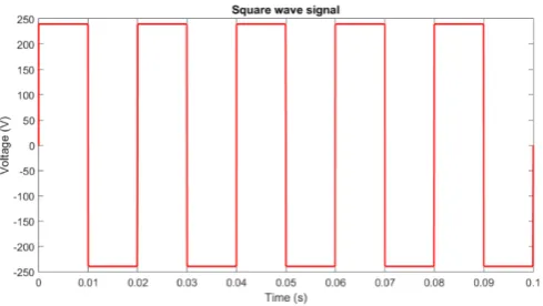
types of AC output which are square wave, modified square wave and pure sine wave
[50]. Square wave are the most inexpensive conversion method as shown in Figure 2.1.
The output can be achieve with a half-wave bridge where switching regulates the DC
source form positive to negative. Hence, square wave output is a very low quality AC
9
[image:29.595.196.441.413.546.2]Figure 2.1: Illustrated square wave signal
Figure 2.2 shows a modified sine wave which is also known as staircase
waveform where the output is a cascade of multiple voltage levels. The step waveform
has capability of harmonics reduction which improves the voltage quality. The
advantage over the square wave is the higher efficiency.
Figure 2.2: Illustrated modified square wave signal
Figure 2.3 shows pure sine wave which is the most expensive inverter type
among them. However, it is the optima source for all devices. The term ‘expensive’
refers to components use in the filter system applied. In this research, inverter is the
10
Figure 2.3: Illustrated pure sine wave signal
2.3 Voltage source inverter
Inverters are classified into two main group that are voltage source inverter (VSI) and
current source inverter (CSI). VSI operate independently generate voltage waveform
output. CSI on the other hand, operate independently to generate current waveform
output. Both of the inverters are widely used in power conversion application. The
development of VSI is better as compared to CSI due to the early foundation. The
capability of power electronics switches enable VSI to be more feasible for high power
application. A comparative research study [3] was done and summarised pros and cons
of inverter by the author. VSI overpowers CSI in terms of the DC component size and
cost. Besides that, VSI also show advantages in shorter time to reach steady-state as
compared to CSI. For the low switching frequency aspect, CSI is in the lead. However,
in terms of low switching frequency, VSI leads with lower loss. The overall
comparison shows the advantages of VSI in the power conversion area.
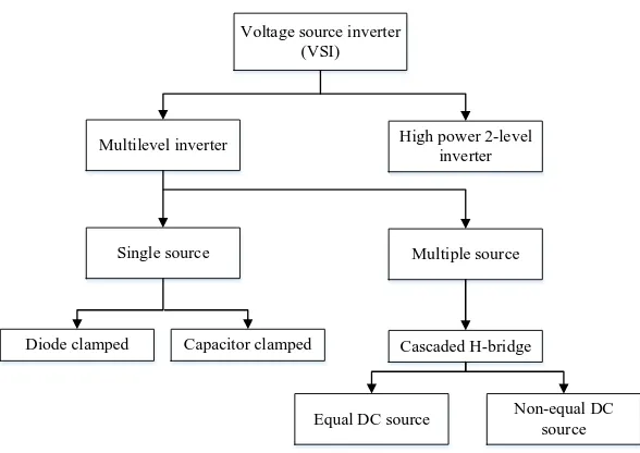
Figure 2.4 shows VSI families where there are two categories which are
multilevel inverter and high power two-level inverter. High power two-level inverter
is the conventional inverter operating with high complexity and bulky filter system.
Multilevel inverter is classified into a single source and multiple sources. Single source
type multilevel inverter are diode clamped and capacitor clamped type. Both types of
inverter are capable to operate with a single DC source in single or three phase system.
11
requires an individual DC source where number of DC source determines the number
of voltage levels generated. However, the multiple source inverter encounters problem
which is equal DC sources or an unequal DC source condition [4, 5].
Voltage source inverter (VSI)
Multilevel inverter High power 2-level inverter
Single source Multiple source
Diode clamped Capacitor clamped Cascaded H-bridge
[image:31.595.173.467.180.388.2]Equal DC source Non-equal DC source
Figure 2.4: Voltage source inverter family
In recent years, multilevel inverter is widely developed and researched due to
its advantages over the conventional inverter. Conventional inverter such as high
power 2-level inverter has a square waveform quality output. Bulky capacitor and
complex filter system are required in order to support high harmonic voltage output.
Besides that, high power rating switches are is required to handle high 𝑑𝑑𝑑𝑑
𝑑𝑑𝑑𝑑 stress from the high voltage level. Hence, multilevel inverter is proposed to overcome the problem.
Multilevel inverter is applies the concept of the voltage sum of different
voltage source to generate multiple times higher voltage level output. It has the
advantage of generating inclusion of the high quality staircase waveform thus reducing
electromagnetic compatibility problems, lower harmonic distortion and reduced 𝑑𝑑𝑑𝑑 𝑑𝑑𝑑𝑑
stress on the switch. Multilevel inverter functions in both fundamental and high
frequency switching conditions. The possibility of operating low frequency switches
12
Several multilevel inverter topologies had been introduced since the year 1975.
Amongst them, the most common topologies that used are the H-bridge cascade
inverter, capacitor clamping inverter and diode clamping inverter [7]. There are
various topologies for multilevel inverter using similar concepts and propose modified
multilevel inverter such as example reversing voltage, modular and generalized
multilevel current source inverter.
The power electronics switches configuration is determined by the modulation
technique. There are a number of modulation techniques introduced in the literature
[19]. Sinusoidal pulse width modulation (SPWM) method appear to be the most
popular method. This method gain benefits where the switching frequency is several
kilohertz (Hz) above which unwanted harmonic when switching will only appear at
high harmonics order. Thus, filter system can be much simple and cheap.
Modulation methods are widely discussed in the current research trend. It is
part of the possible improvement method in reducing the total harmonics distortion for
an output. However, the research objective include to reduce both switching frequency
and THD by applying other modulation methods as compared to conventional PWM
method.
In the term of market values, specification high efficiency, low cost and
reliability are highly sensitive issue of manufacture compares. Each level of multilevel
inverter shows the increasing quality of output where the number of voltage level
increases.
2.4 Multilevel inverter
The basic concept behind a multilevel inverter is achieving high voltage level power
with the several low voltage level power by aid of power electronics switches to
synthesize a staircase output voltage waveform. Multilevel inverter has been
introduced since the year 1975s. The first patented multilevel inverter concept is the
13
new topology is proposed in year 1981 [10]. The new topology applies the
characteristics of diode in current flow to synthesize a staircase AC output waveform
which is known as diode clamped multilevel inverter (DC-MLI) or Neutral-Point
Clamp inverter. In year 1992, capacitor clamped multilevel inverter (CC-MLI) was
proposed by Meynard and Forch by applying capacitor to synthesize different voltage
level [11]. After that, numerous new topologies of multilevel inverter have been
proposed from the modification of the previous three main multilevel inverter concept
or hybrid mode. The topologies include generalized multilevel inverter [12], hybrid
multilevel inverter [13-15], soft–switched multilevel inverter [16]. DC-MLI, CC-MLI
and CHB-MLI are discussed in more detail in terms of concept, topology, switching
configuration, advantage and disadvantages in this section.
2.4.1 Diode Clamped Multilevel Inverter
The concept of DC-MLI function is using diode to limit the voltage current flow
pathway and give different voltage level output based on the switch condition [30].
Capacitors in series with a neutral point in the middle of capacitor line as the separation
of source function.
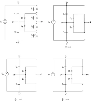
Figure 2.5 shows 3-level diode clamped multilevel inverter topology for single
phase. The inverter is connected with clamping diode in series in order to provide all
diodes with the same voltage rating. C1 and C2 acts as the DC link bus to separate the
DC source into 2 which is Vdc/2 for each capacitor. S1 to S4 are the power electronic
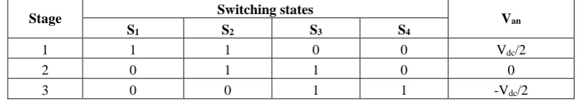
switches which control the switching to alter Vao. Table 2.1 show the switching
configurations for a single phase 3-level DC-MIL. When S1 and S2 are on and S3 and
S4 are off, the voltage output is Vdc/2. When S2 and S3 are on and S1 and S4 are off,
the voltage output is 0. When S1 and S2 are off and S3 and S4 are on, the voltage
output is -Vdc/2. The line voltage are generates only 2-levels but when in three phase
configuration, the delta or wye connection enables line-to-line voltage achieve 3-level
14
The main concept of DC-MLI is using diodes to limit the voltage stress of the
power device. The topology of DC-MLI has a general component formula where
assuming 𝑚𝑚 is the number of voltage level desired, then the number of switches
needed is 2(𝑚𝑚 −1), number of capacitors needed is 𝑚𝑚 −1 and number of clamping
diodes needed is 𝑚𝑚 −1 .The line functions as DC-bus which divides a single DC
supply into even number. The capacitor line is connected with the clamping diodes
pairs of 𝑚𝑚 −1 where 𝑚𝑚 is the number of voltage level that is desired. Photovoltaic
[image:34.595.179.498.288.643.2]arrays were connected as DC supply for the inverter [17,51].
15
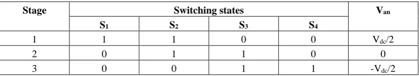
Table 2.1: 3-level diode clamped multilevel inverter switching configuration
Stage Switching states Van
S1 S2 S3 S4
1 1 1 0 0 Vdc/2
2 0 1 1 0 0
3 0 0 1 1 -Vdc/2
The advantages and disadvantages for DC-MLI are discussed below.
Advantages:
• All phase sharing same DC bus.
• Capacitor can be charged in a group for DC bus.
• High efficiency for fundamental frequency switching.
Disadvantages:
• Not suitable for high number of voltage level due to the possible growth of
components needed.
2.4.2 Capacitor Clamped Multilevel Inverter
The structure of CC-MLI is similar to DC-MLI where the difference is that capacitor
is used to replace the diode clamp to hold the desire voltage.
Figure 2.6 shows a 3-level capacitor clamped multilevel inverter topology.
CC-MLI generally uses capacitors and power electronic switches. Consider 𝑚𝑚 as the
number of inverter voltage levels, 𝑚𝑚 −1 is the number of capacitor required on the
DC-bus and 2(𝑚𝑚 −1)power electronic switches are needed. Clamping capacitor
number is depending on the position and number of levels of inverter desired. Both C1
and C2 illustrated in Figure 2.5 is the DC-bus capacitor which are similar to that in the
DC-MLI. C3 is the clamping capacitor and S1, S2, S3, S4 are the power electronics
switches. The clamping capacitors advantage over no block voltage as DC-MIL which
increases the number of switching combination. Table 2.3 shows the 3-level capacitor
clamped multilevel inverter switching configuration. When S1 and S2 are on and S3
and S4 are off, Van is equal to Vdc/2 due to the current flow sequence. When S2 and S3
16
S4 are on, the voltage output is -Vdc/2. The sequence are the same as in DC-MLI but
there are more configurations that can be plotted and the Table 2.2 is one of the
possible solution.
Since the same current through all the active capacitors, energy can be
transferred from more charged capacitors to less charged capacitors to balance the
capacitors voltages. However the as the capacitor number increase for achieve higher
[image:36.595.113.527.268.698.2]voltage level, the issue of voltage imbalance in DC link occur [6, 7, 52-55].
17
Table 2.3: 3-level capacitor clamped multilevel inverter switching configuration
Stage Switching states Van
S1 S2 S3 S4
1 1 1 0 0 Vdc/2
2 0 1 1 0 0
3 0 0 1 1 -Vdc/2
The advantages and disadvantages of CC-MLI are discussed below. Advantages:
• Controllable active and reactive power flow.
• Reduce duration of sags and outages. Disadvantages:
• All capacitors need to be charged up to same voltage level before start-up.
• Capacitors are more expensive and bulky compared to diodes.
• Voltage control on all capacitors for voltage levels is complicated.
2.4.3 Cascaded H-Bridge Multilevel Inverter
Two or more separate DC sources in a full bridge are placed in series to generate a
staircase AC output waveform voltage. Figure 2.7 shows a 2-level CHB-MLI topology.
CHB-MLI requires fewer components where each voltage level requires the same
amount of components. However, the number of sources is higher since 𝑚𝑚 voltage
level inverter, 𝑠𝑠 = 𝑚𝑚−1
2 sources are required. The number of sources s is also equal to the number of full bridge modules.
The CHB-MLI switching configuration is similar to the other topology. When
S1 and S4 are on and S2 and S3 are off, voltage Van is equal to Vdc due to the current
flow sequence. When S1 and S2 are on and S3 and S4 are off, the voltage output is 0.
When S1 and S2 are off and S3 and S4 are on, the voltage output is 0. When S1 and S4
18
Every full-bridge module has four diodes and four switches 𝑠𝑠 in turn giving
the CHB-MLI 2(𝑚𝑚 −1) = 4𝑠𝑠 diodes and switches. When making a three-phase
inverter with the topology, the number of needed components are multiplied by three
for all components since there is no common DC-bus to share.
Applications suitable for the CHB-MLI are for example where photovoltaic
cells, battery cells or fuel cells are used [5, 18, 19]. The consideration of number of
level for CHB-MLI are different from other. The calculation of CHB-MLI of number
of voltage levels are including the negative side of each voltage level while other
[image:38.595.138.489.323.610.2]topologies do not.
Figure 2.7: 2-level cascaded H-bridge multilevel inverter topology
The advantages and disadvantages of CHB-MLI are discussed below. Advantages:
• Achieve higher voltage level with same component as compared to other topologies.
19
Disadvantages:
• Limited application due to separate DC source characteristic.
Overall, the comparison of components for single phase are show in Table 2.3
where 𝑚𝑚 is the number of inverter level. Generally the number of switches for all
three topology are the same including the diode for each switch. The difference
between the topologies component are the clamping type which was diodes or
capacitors and the DC-bus capacitor. CHB-MLI shows advantage of less components
needed as there is no requirement for clamping and DC-bus.
Table 2.2: Components comparison of multilevel inverter topologies
Component DC-MLI CC-MLI CHB-MLI
Switches 2(𝑚𝑚 −1) 2(𝑚𝑚 −1) 2(𝑚𝑚 −1)
Diodes 2(𝑚𝑚 −1) 2(𝑚𝑚 −1) 2(𝑚𝑚 −1)
Clamping diodes (𝑚𝑚 −1)(𝑚𝑚 −2) 0 0
Clamping capacitor 0 (𝑚𝑚 −1)(𝑚𝑚 −2)/2 0
DC bus capacitors (𝑚𝑚 −1) (𝑚𝑚 −1) 0
2.5 Total harmonic distortion
One of the principal sources of harmonic is converter or also known as inverter
also. The non-sinusoidal current generated contain high harmonic characterises.
Inverter implementing the power electronic switching devices such as diodes,
thyristors, IGBT, GTO and others. The process of power conversion switching causes
the generation of harmonics. The gap of the current draw out from source during
switching cause harmonic occurs. Harmonic current cause device overheating and
20
Total harmonic distortion is signal measurement of the ratio between the
harmonic components and the fundamental frequency component which can be
calculated as Equation 2.1,
( )
22 32 2 1THD % V V Vn 100
V
+ + +
=
(2.1)
Where Vn is the RMS voltage of the nth harmonic and n = 1 is the fundamental frequency. The number of the harmonics after the fundamental is considered a ruler
for the quality of a power sources. The lower the number of harmonic gives a higher
quality source.
2.6 Modulation techniques
Modulation technique have greatly influence on harmonics effect of multilevel inverter.
The most popular modulation method is the carrier based PWM, space vector PWM
and the harmonic based PWM. Each modulation method exist with pros and cons. The
modulation method are generally separate into fundamental switching frequency type
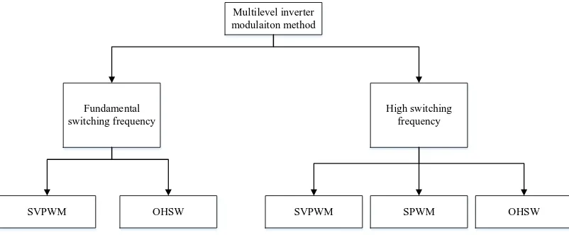
and high switching frequency type. Figure 2.8 shown the classification of multilevel
inverter modulation method. For fundamental switching frequency categories included
SVPWM and OHSW which mean the switches switch for on off per cycle. While for
high switching frequency categories, SPWM, SVPWM and OHSW is included.
SPWM method found to be only applicable in high switching frequency modulation
21
Multilevel inverter modulaiton method
Fundamental switching frequency
High switching frequency
[image:41.595.117.518.74.240.2]SVPWM OHSW SVPWM SPWM OHSW
Figure 2.8: Classification of multilevel inverter modulation method
2.6.1 Carrier based pulse width modulation
Carrier based pulse width modulation method is referring to the sinusoidal pulse width
modulation in cooperating with multiple type of barrier parameter. SPWM operational
theory is that the desired pulse width is obtained by comparison of triangular wave
which acts as a carrier and sinusoidal wave of desired fundamental frequency [56].
SPWM modulation have several branches, which are phase disposition, phase
opposition disposition and phase shift modulation method. Characteristic of each
method is shown as below where 𝑚𝑚 is referring to be voltage levels.
Phase disposition modulation (PD)
• PD method is part of the multi carrier PWM method where the number of
carries depend on the multilevel inverter. The method applied (𝑚𝑚 −1) carrier
where m refers number of sources.
Phase opposition disposition modulation (POD)
• POD method is similar to the PD method. Both are applying (𝑚𝑚 −1) carrier
but the difference is the 180 degree phase out of bottom carrier by referring the
zero reference.
22
• PS method is each (𝑚𝑚 −1) carrier is phase shifted by 90 degree.
The carrier based pulse had advantages over high order harmonics can be done due
to operate in high switching frequency. The high order harmonics are more ease to
be filter and removed as compared to low order harmonics. The advantages also
lead to disadvantages where switching frequency need to be very high where
life-span of the switches is no preserved.
2.6.3 Third harmonics injection pulse width modulation method
Third harmonic injection is an upgrade method to be apply onto SPWM to utilize the
available DC bus supply voltage. A 3rd harmonics with peak magnitude of 1 6 to modulation waves is added into the general SPWM system which resultant reduction
of peak voltage output but increase the fundamental component voltage [58]. Third
harmonic injection pulse width modulation technique capable to overcome the existing
problem of SPWM that is lower output voltage than the supplied input voltage.
However, this method still facing high switching loss problem as SPWM.
2.6.3 Space vector pulse width modulation
Space vector pulse width modulation method is an algorithm to control the switching
pulse in order to create AC waveform. Each combination of switching stage is
converted into a space vector diagram. This method assigns each possible switching
configuration into a space vector diagram. Then applying a mathematical calculation
on the vector to get the switching timing. The proses start from sector identification.
Once the sector has been identified, switching time for each switch is calculated. Lastly,
identifying the switching state of the switch, whether is on or off [55, 57]. This
modulation method is very systematic and operate both fundamental and high
switching frequency. However, it is limited to three voltage level if facing unbalance
23
2.6.4 Harmonics Based Optimized harmonics stepped waveform modulation
Optimized harmonics stepped waveform (OHSW) modulation is a modulation
technique to operate an inverter in low switching frequency [20]. The modulation
method operate with fundamental frequency which generally increase life span of
switching device and reduce the power losses through reduces harmonics. The
possibility to generate filterless output is possible by adapting this technique.
2.7 Selective harmonics elimination
The characterises of this modulation method are capable to remove low order
harmonics and apply on equal or unequal DC source multilevel inverter [20]. Several
methods were found in the study of literature to solve the non-linear SHE equation.
The newton-raphson method is one of the methods found in [21].
Newton-raphson is an iterative method which begins with an initial value and converges at a
zero for the nonlinear equation calculation. Hence, it was applied into the switching
angles determination. The result obtained are in multiple sets which require of testing
and simulation to obtain the best. The method gives clear switching angle and highly
accurate result with very small increment step. However, the method is time
consuming since it computes all the possible angles set, then refine to find the best one.
Bee algorithm is an optimization algorithm which mimics the bees natural
behaviour in searching food. The optimization algorithm is capable to resolve the
nonlinear equation of switching angles as shown as the result in [22]. Bee algorithm is
a high approaching global solution method where it has a good convergence rate. The
high approaching global solution shows a high viable solution set also. Hence, bee
algorithm also takes a longer time to optimize the best result.
Bat algorithm is lately introduced by several researchers [18, 19]. It utilizes the
24
selective harmonics elimination as compared to bee algorithm and a genetic algorithm
is shown. Hence the method is still currently under developing stage to optimize and
enhance the performance.
Particle swarm algorithm is also one of the method to be applied in the
multilevel switching angle. The algorithm also show capability in resolving switching
angle function where the low harmonics are clearly optimized [23].
2.8 Previous Research Work on multilevel inverter
Chiasson et. al.[59-61], optimize switching angle had been shown to be helpful in
reducing harmonics. The result show for certain amount order of harmonics has been
successfully reduced or eliminated by Resultant Theory method. The resultant show
highly complex where the expression polynomials reaching 22th degree. Hence,
obvious increasing of complexity shown in the result as the number of voltage level
increase.
Engin Ozdemir et al.[62], standalone photovoltaic system applying diode
clamped multilevel inverter with fundamental frequency modulation. The switching
angle is calculated by applying transcendental equations calculation method. The
result show success of harmonics elimination. According to other literature [76, 77], it
was found that the transcendental equation is useful in single source application. When
apply this method in unbalance DC sources, the equation became complex and hardly
capable to be solve by contemporary computer algebra software tools if the number of
voltage level exceeding three.
Several studies on different multilevel inverter using various method of
optimization to reduce harmonics distortion have ensued. N. Farokhnia et al. (2010)
[35], shown a calculation method by using calculation of the line to line THD with
equal DC sources for five level cascaded H-bridge multilevel inverter. The
118
REFERENCES
[1] Mattick, C.S., E. Williams, and B.R. Allenby, “Historical trends in global energy consumption,” Technology and Society Magazine, IEEE, vol. 29, pp. 22-30, 2010.
[2] Daher, S., Schmid, J., & Antunes, F. L., “Multilevel inverter topologies for stand-alone PV systems,” IEEE transactions on industrial electronics, pp. 2703-2712, 2008.
[3] Azmi, S., “Comparative analysis between voltage and current source inverters in grid-connected application,” Renewable Power Generation on IET Conference, pp. 1-6, 2011.
[4] Yunus, H.I. and R.M. Bass, “Comparison of VSI and CSI topologies for single-phase active power filters,” Power Electronics Specialists Conference IEEE, vol. 2, pp. 1892-1898, 1996.
[5] Lakwal, J., Deshpande, D. M., Suresh, A., & Mittal, A., “Cascaded Multilevel Inverter Topologies for Photovoltaic Power Generation Systems,” International Journal of ChemTech Research CODEN (USA): IJCRGG ISSN, pp. 0974-4290, 2013.
[6] Ozdemir, E., S. Ozdemir, and L.M. Tolbert, “Fundamental-frequency-modulated six-level diode-clamped multilevel inverter for three-phase stand-alone photovoltaic system,” Industrial Electronics on IEEE Transactions, vol. 56, pp. 4407-4415, 2009.
119
[8] Kim, T. J., Kang, D. W., Lee, Y. H., & Hyun, D. S. , “The analysis of conduction and switching losses in multi-level inverter system,” Power Electronics Specialists Conference, vol. 3, pp. 1363-1368, 2001.
[9] Baker, R. and L. Bannister, “Electric Power Converter,” Electric Power Converter. US Patent 3 867 643, 1975.
[10] Nabae, A., I. Takahashi, and H. Akagi, “A new neutral-point-clamped PWM inverter,” Industry Applications on IEEE Transactions, vol. 5, pp. 518-523, 1981.
[11] Meynard, T. and H. Foch, “Multi-level conversion: high voltage choppers and voltage-source inverters,” Power Electronics Specialists Conference IEEE, pp. 397-403, 1992.
[12] Peng, F.Z, “A generalized multilevel inverter topology with self voltage balancing,” IEEE Transactions on industry applications, vol. 37, pp. 611-618, 2001.
.
[13] Hill, W. and C. Harbourt, “Performance of medium voltage multi-level inverters,” Industry Applications Conference, Thirty-Fourth IAS Annual Meeting, vol. 2, pp. 1186-1192, 1999.
[14] Manjrekar, M.D., P.K. Steimer, and T.A. Lipo, “Hybrid multilevel power conversion system: a competitive solution for high-power applications,” IEEE Transactions on Industry Applications, vol. 36, pp. 834-841, 2000.
[15] Lai, Y.-S. and F.-S. Shyu, “Topology for hybrid multilevel inverter,”. IEE Proceedings-Electric Power Applications, vol. 149, pp. 449-458, 2002.
[16] Song, Byeong-Mun, Juhyung Kim, Jih-Sheng Lai, Ki-Chul Seong, Hae-Jong Kim, and Sun-Soon Park, “A multilevel soft-switching inverter with inductor coupling,” IEEE Transactions on Industry Applications, vol. 37, pp. 628-636, 2001.
[17] Kanimozhi, M. and P. Geetha, “A new boost switched capacitor multilevel inverter using different multi carrier PWM techniques,” Circuit, Power and Computing Technologies on International Conference, pp. 432-437, 2014.
120
[19] Ganesan, K., K. Barathi, P. Chandrasekar, and D. Balaji., “Selective Harmonic Elimination of Cascaded Multilevel Inverter Using BAT Algorithm,” Procedia Technology, 21, pp. 651-657, 2015.
[20] Aghdam, M.H., S. Fathi, and G. Gharehpetian, “Comparison of OMTHD and OHSW harmonic optimization techniques in multi-level voltage-source inverter with non-equal DC sources,” Power Electronics, pp. 587-591, 2007.
[21] Kumar, J., B. Das, and P. Agarwal, “Selective harmonic elimination technique for a multilevel inverter,” space, vol. 1, pp. 3, 2008.
[22] Kavousi, A., Vahidi, B., Salehi, R., Bakhshizadeh, M.K., Farokhnia, N. and Fathi, S.H., “Application of the bee algorithm for selective harmonic elimination strategy in multilevel inverters,” Power Electronics on IEEE Transactions, vol. 27, pp. 1689-1696, 2012.
[23] Parkash, A., S. Shimi, and S. Chatterji, “Harmonics Reduction in Cascade H-Bridge Multilevel Inverters Using GA and PSO,” International Journal of Engineering Trends and Technology, vol. 12, pp. 453-465, 2014
[24] Najafi, E., & Yatim, A. H. M., “Design and implementation of a new multilevel inverter topology,” IEEE transactions on industrial electronics, vol. 59, pp, 4148-4154, 2012.
[25] Gandomi, A. A., Saeidabadi, S., Hosseini, S. H., Babaei, E., & Sabahi, M., “Transformer-based inverter with reduced number of switches for renewable energy applications,” IET Power Electronics, vol. 8, pp. 1875-1884, 2015.
[26] Beigi, L. M. A., Azli, N. A., Khosravi, F., Najafi, E., & Kaykhosravi, A, “A new multilevel inverter topology with reduced number of power switches,” Power and Energy on IEEE International Conference, pp. 55-59, 2012.
[27] Miloudi, H., Bendaoud, A., Miloudi, M., Gourbi, A., & Slimani, H., “Common mode conducted electromagnetic interference in inverter fed-AC motor,”
Przegląd Elektrotechniczny (Electrical Review), pp. 272-275, 2010.
[28] S. Devaraj, Anitha G. S., “POD-PWM Based Capacitor Clamped Multilevel Inverter,” International Journal of Technical Research and Applications, vol. 3, pp. 80-82, 2015.
121
[30] Ozdemir, E., S. Ozdemir, and L.M. Tolbert, “Fundamental-Frequency-Modulated Six-Level Diode-Clamped Multilevel Inverter for Three-Phase Stand-Alone Photovoltaic System,” IEEE Transactions on Industrial Electronics, vol. 56, pp. 4407-4415, 2009.
[31] Raghu, M. and V. Goutham, “Control of a three-phase cascaded h-bridge multilevel inverter for stand-alone PV System,” International Journal of Modern Engineering Research, vol. 2, pp. 278-282, 2012.
[32] Chen, A., & He, X., “Research on hybrid-clamped multilevel-inverter topologies,” IEEE Transactions on Industrial Electronics, vol. 53, pp. 1898-1907, 2006.
[33] Colak, I., Kabalci, E., & Bayindir, R., “Review of multilevel voltage source inverter topologies and control schemes,” Energy Conversion and Management, vol. 52, 1114-1128, 2011.
[34] Peng, F. Z., Qian, W., & Cao, D., “Recent advances in multilevel converter/inverter topologies and applications,” Power Electronics Conference ,pp. 492-501, 2010.
[35] Farokhnia, N., Vadizadeh, H., Kadkhoda, F., & Vahabzadeh, A., “Formulation of the line voltage THD, case I: Multilevel inverter with equal DC sources,” Power Electronics Conference, pp. 1244-1251, 2010.
[36] Patel, H. S., & Hoft, R. G., “Generalized harmonic elimination and voltage control in thryristor inverters: Part II-voltage control technique,” IEEE Transactions on Industry Applications, vol. 10, pp. 666-673, 1974.
[37] Li L, Czarkowski D, Liu Y, Pillay P, “Multilevel selective harmonic elimination PWM technique in series-connected voltage inverters,” IEEE Transactions on Industry Applications, vol. 36, pp. 160-170, 2000.
[38] Fei, W., Du, X., & Wu, B., “A generalized half-wave symmetry SHE-PWM formulation for multilevel voltage inverters,” IEEE Transactions on Industrial Electronics, vol. 57, pp. 3030-3038, 2010.
[39] Enjeti PN, Ziogas PD, Lindsay JF, “Programmed PWM techniques to eliminate harmonics: A critical evaluation,” IEEE Transactions on Industry Applications, vol. 26, pp. 302-316, 1990.
122
[41] Wilson, T.G., “The evolution of power electronics,” IEEE Transactions on Power electronics, vol. 15, pp.439-446, 2000.
[42] Mariam, L., M. Basu, and M.F. Conlon, “A review of existing microgrid architectures,” Journal of Engineering, 2013.
[43] Binduhewa, P.J., M. Barnes, and A. Renfrew., “Standard microsource interface for a MicroGrid,” SmartGrids for Distribution IET-CIRED, pp. 1-4, 2008.
[44] Zhang, J. and M.C. Gursoy., “The impact of renewable energy resources on demand response management in a smart grid,” IEEE 13th International Workshop on Signal Processing Advances in Wireless Communications (SPAWC), pp. 475-479, 2012.
[45] Ross, M., Hidalgo, R., Abbey, C. and Joós, G., “Energy storage system scheduling for an isolated microgrid,” IET Renewable Power Generation, vol. 5, pp. 117-123, 2011.
[46] Lasseter, R.H., “MicroGrids,” IEEE Power Engineering Society Winter Meeting, vol. 1, pp. 305-308, 2002.
[47] Mohan, N. and T.M. Undeland., “Power electronics: converters, applications, and design,” John Wiley & Sons, 2007.
[48] Starke, M., L.M. Tolbert, and B. Ozpineci., “AC vs. DC distribution: A loss comparison,” IEEE/PES Transmission and Distribution Conference and Exposition, pp. 1-7, 2008.
[49] Owen, E.L., “History [origin of the inverter],” Industry Applications Magazine, IEEE, pp. 64-66, 1996.
[50] Poddar, G. and M.K. Sahu, “Natural harmonic elimination of square-wave inverter for medium-voltage application,” IEEE Transactions on Power Electronics, vol. 24, pp. 1182-1188, 2009.
[51] Naderi, R. and K. Smedley, “A new hybrid active neutral point clamped flying capacitor multilevel inverter,” IEEE Applied Power Electronics Conference and Exposition (APEC), pp. 794-798, 2015.
123
[53] Kouzou, A., H. Abu Rub, A. Iqbal, Sk Moin Ahmed, B. S. Khaldi, M. O. Mahmoudi, M. S. Boucherit, and R. Kennel., “Selective harmonics elimination for a three-level diode clamped five-phase inverter based on particle swarm optimization,” 37th Annual Conference on IEEE Industrial Electronics Society, pp. 3495-3500, 2011.
[54] Ozdemir, S., Ozdemir, E., Tolbert, L. M., & Khomfoi, S., “Elimination of harmonics in a five-level diode-clamped multilevel inverter using fundamental modulation,” Power Electronics and Drive Systems on 7th International Conference, pp, 850-854, 2007.
[55] Thomas, R. V., Rakesh, E., Jacob, J., & Chitra, A., “Identification of optimal SVPWM technique for diode clamped multilevel inverter based induction motor drive,” Electrical, Computer and Communication Technologies (ICECCT), pp. 1-6, 2015.
[56] Nedumgatt, Jacob James, K. B. Jayakrishnan, S. Umashankar, D. Vijayakumar, and D. P. Kothari, “Perturb and observe MPPT algorithm for solar PV systems-modeling and simulation,” India Conference (INDICON), pp. 1-6, 2011.
[57] Mirafzal, B., M. Saghaleini, and A.K. Kaviani, “An SVPWM-based switching pattern for stand-alone and grid-connected three-phase single-stage boost inverters,”. Power Electronics on IEEE Transactions, vol. 26, pp. 1102-1111, 2011.
[58] Jose, J., Goyal, G. N., & Aware, M. V., “Improved Inverter Utilisation Using Third Harmonic Injection,” Power Electronics, Drives and Energy Systems on International Conference, pp. 1-6, 2010
[59] Chiasson, J., Tolbert, L., McKenzie, K., & Du, Z., “Eliminating harmonics in a multilevel converter using resultant theory,” Power Electronics Specialists Conference, IEEE 33rd Annual, vol. 2, pp. 503-508, 2002.
[60] Chiasson, J., Tolbert, L. M., McKenzie, K., & Du, Z., “A complete solution to the harmonic elimination problem,” Applied Power Electronics Conference and Exposition, Eighteenth Annual IEEE, vol. 1, pp. 596-602, 2003.
124
[62] Ozdemir, E., Ozdemir, S., & Tolbert, L. M., “Fundamental-frequency-modulated six-level diode-clamped multilevel inverter for three-phase stand-alone photovoltaic system,” IEEE Transactions on Industrial Electronics, vol. 56, pp. 4407-4415, 2009.
[63] Cecati, C., Ciancetta, F., & Siano, P., “A multilevel inverter for photovoltaic systems with fuzzy logic control,” IEEE Transactions on Industrial Electronics, vol. 57(12), pp. 4115-4125, 2010.
[64] M.V.Vinod kumar, D.Kamala, “Comparative Analysis of Different Modulation Techniques For Five Level Diode Clamped Inverter With Boost Converter,”. Journal of Precious Engineering Research and Applications, vol. 1, pp. 05 -11, 2016.
[65] Abd-El-Wahed, W., A. Mousa, and M. El-Shorbagy, “Integrating particle swarm optimization with genetic algorithms for solving nonlinear optimization problems,” Journal of Computational and Applied Mathematics, vol. 253: p. 1446-1453, 2011.
[66] Debnath, S. and R. Narayan, “THD Optimization in 13 level photovoltaic inverter using Genetic Algorithm,” International Journal of Engineering Research and Applications, vol 2, pp. 385-389, 2012.
[67] Hosseini, S. H., Sadigh, A. K., Barakati, S. M., & Kangarlu, M. F., “Comparison of SPWM technique and selective harmonic elimination using genetic algorithm,” Electrical and Electronics Engineering, pp. 1-178, 2009.
[68] Perumal, M. and D. Nanjudapan, “Performance enhancement of embedded system based multilevel inverter using genetic algorithm,” Journal of Electrical Engineering, vol. 62, pp. 190-198, 2011.
[69] Ozpineci, B., L.M. Tolbert, and J.N. Chiasson., “Harmonic optimization of multilevel converters using genetic algorithms,” IEEE 35th Annual Power Electronics Specialists Conference, vol. 62, pp.190-198, 2011.
[70] Vas, Peter, “Artificial-intelligence-based electrical machines and drives: application of fuzzy, neural, fuzzy-neural, and genetic-algorithm-based techniques,” Oxford university press, vol. 45, 1999.
125
[72] Adedeji, A, “Genetic (evolutionary) algorithm: introduction and its use as an engineering design tool,” Olad Publication and Printing Enterprises, Nigeria, pp. 978-8115, 2007
[73] Song, M.-P. and G.-C. Gu. , “Research on particle swarm optimization: a review. in Machine Learning and Cybernetics,” Proceedings of on International Conference, vol. 4, pp. 2236-2241, 2004.
[74] Eberhart, R.C. and J. Kennedy. , “A new optimizer using particle swarm theory,” IEEE Proceedings of the sixth international symposium on micro machine and human science. vol. 43, pp. 39-43, 1995.
[75] Eberhart and S. Yuhui., “Particle swarm optimization: developments, applications and resources,” evolutionary computation, vol.1, pp. 81-86, 2001.
[76] Chiasson, J. N., Tolbert, L. M., Du, Z., & McKenzie, K. J., “The use of power sums to solve the harmonic elimination equations for multilevel converters,” EPE Journal, vol. 15, pp.19-27, 2005
[77] Tolbert, L. M., Chiasson, J., McKenzie, K., & Du, Z., “Elimination of harmonics in a multilevel converter with nonequal DC sources,” In Applied Power Electronics Conference and Exposition, vol. 1, pp. 589-595, 2003.