International Research Journal of Mathematics, Engineering and IT Vol. 3, Issue 5, May 2016 IF- 3.563 ISSN: (2349-0322)
© Associated Asia Research Foundation (AARF)
Website: www.aarf.asiaEmail : [email protected] , [email protected]
OPTIMIZATION OF DRILLING PARAMETERS FOR HFRP
COMPOSITE USING ANOVA ANALYSIS
K. V. Satyanarayana1, D. V. V. Krishna Prasad2
1
P.G. Student, 2Professor,
Department of Mechanical Engineering
R.V.R. &.J.C. College of Engineering, Guntur, Andhra Pradesh, India.
ABSTRACT
Hybrid fiber reinforced polymer (HFRP) composite is a novel methodology in fiber reinforced
polymer (FRP). A Laminate is prepared by stacking of alternative layers of carbon fiber
reinforced lamina and glass reinforced laminas making a laminate thickness of 4mm.
Experiments were conducted HFRP composite for full factorial design to evaluate torque and
thrust force at different drilling parameters, such as drill point angle, feed rate and cutting
speed. Utilizing (ANOVA) approach and (S/N) ratio analysis the drilling parameters were
optimized.
Keywords- ANOVA, Drilling parameters, Factorial design, HFRP,
1. Introduction
Hybrid fiber reinforced polymer (HFRP) composite is an advanced fiber reinforced polymer
(FRP) composite that utilized two or more different fibers are used to make a laminate.
Advantage of using this composite is that it is possible to improve the failure strain by
incorporated high elongation fiber like glass fiber into low elongation fiber such as carbon fiber
[1]. Drain grating covers and oil and gas platform are some of the applications HFRP. Holes are
drilling holes on the fiber reinforced polymer (FRP) composite utilizing traditional drilling draw
an incredible it will harm the material's structure because of the unacceptable drilling technique,
for example, the choice of consideration as erroneous drill geometry and despicable
determination of drilling parameters.
.
2. Literature Survey
.Biran Desai et.al[2]:Investigates on in drilling the quality of hole is an important
requirement for many applications. Thus the choice of optimized cutting parameters is very
important for controlling the required hole quality. The focus on the present study optimize the
parameters through work piece circularity and hole size. This paper represents a full factorial and
ANOVA for formed on thin CFRP laminates using point angles 60 and helix angle 30. By
varying the parameters spindle speeds and feed rate to determine the optimum of hole diameter
and circularity. Vijayan Krishna raj et.al[3]:This paper represents an experimental
investigation of full factorial deign on thin CFRP laminates using K20 carbide drill by varying
drilling parameters spindle speed, feed rate. To determine the optimum conditions of hole
diameter and delamination by using ANOVA and Genetic algorithm method is used in MAT lab.
Shunmughesh et.al[4]:In this study composite undergo drilling and L27 orthogonal array is
used to determine delamination and surface roughness by varying the parameters spindle speed
feed rate point angles to determine the optimum conditions of hole diameter in the Grey
relational analysis performed. Mohd Azuwan Maoinser et.al[5]:Investigates on drilling of
Hybrid Fiber Reinforced Polymer(HFRP) and this paper presents optimisation of drilling
parameters by varying parameters such as feed rate, spindle speed by using the full factorial
design experiment and combination of ANOVA and signal to noise ratios. M.Ramesh
et.al[6]:The aim of the experiment emphasize machining characteristics of HFRP by varying the
parameters cuttings speed and feed rate, point angles and tool diameter. This paper presents the
drilling induced damages is analysed with Scanning Electron Microscopy (SEM) analysis to
reduce the delamination factor. B.V.Kavad et.al[7]:This paper presents the influence of
machining parameters on the delamination damage of Glass Fiber Reinforced Polymer (GFRP)
during drilling by varying the parameters spindle feed rate and also measure the minimum thrust
force. M.Saravanan et.al[8]:This paper presents composite materials are used in air craft
hole which leads to loosening of rivets in joining various structures. For this by varying the
parameters like cutting speed feed rate to determine the optimum hole eccentricity and M.R.R.
by using Genetic Algorithm technique, numerical method and soft computing technique. J.Babu
et.al[9]:Investigates the during drilling operations is hard to carry out the induced delamination.
This paper presents the optimisation of delamination by conducting drilling experiments using
Taguchi’s L25 orthogonal array and ANOVA by varying the parameters cutting speed and feed
rate.Vinod Kumar.V et.al[10]:This paper presents during drilling carry out induced
delamination. To determine the optimization of delamination and hole quality by varying the
parameters cutting speed point angle chisel edge width. In this work L9 orthogonal array used
and ANOVA was conducted to determine significance and minimize the thrust force and torque.
Suresh.N et.al[11]:Investigates the various drilling parameters like different twist drill bits of
different point angles and deferent materials have been taken and the thrust force and torque
measure for different machining conditions by using the DEFORM 3D Software in this simulate
drilling process and measure the thrust force and torque by varying feed rate, spindle speed and
point angles to determine the optimum values of thrust force and torque.
3. MATERIAL PREPARATION
Materials Used to Prepare A Composite Laminate:
1. Carbon Fiber.
2. Glass fiber
3. Epoxy Resin.
4. Hardener.
3.1. Carbon Fiber:
Carbon fiber is a material consisting of fibers about 5–10 μm in diameter and composed
mostly of carbon atoms. To produce carbon fiber, the carbon atoms are bonded together in crystals
that are more or less aligned parallel to the long axis of the fiber as the crystal alignment gives the
fiber high strength-to-volume ratio (making it strong for its size). Several thousand carbon fibers
are bundled together to form a tow, which may be used by itself or woven into a fabric.
The properties of carbon fibers, such as high stiffness, high tensile strength, low weight,
high chemical resistance, high temperature tolerance and low thermal expansion, make them very
popular in aerospace, civil engineering, military, and motorsports, along with other competition
or plastic fibers.
[image:4.612.73.498.55.211.2]
Fig 3.1 Woven Carbon Filaments Fig3.2 Woven Glass filaments
Carbon fibers are usually combined with other materials to form a composite. When
combined with a plastic resin and wound or molded it forms carbon fiber reinforced polymer (often
referred to as carbon fiber) which has a very high strength-to-weight ratio, and is extremely rigid
although somewhat brittle. However, carbon fibers are also composed with other materials, such as
with graphite to form carbon-carbon composites, which have a very high heat tolerance. Each
carbon filament tow is a bundle of many thousand carbon filaments parallel to each other. A single
such filament is as thin as 5–8 micrometers.
3.2. Glass Fiber:
Over 95% of the fibers used in reinforced plastics are glass fibers, as they are
inexpensive, easy to manufacture and possess high strength and stiffness with respect to the
plastics with which they are reinforced. Their low density, resistance to chemicals, insulation
capacity are other bonus characteristics, although the one major disadvantage in glass is that it is
prone to break when subjected to high tensile stress for a long time
3.3 Laminate Preparation
The HFRP composite specimen of 390mm×340mm×4mm is fabricated by the hand layup
process technique at room temperature. The bi-directional plain weaves type glass fabric and
carbon fabric with 460 GSM is used as reinforcement. The resin used for the preparation of
matrix is Bisphenol A based epoxy resin L-12 and the hardener used is Amino K-6. The resin
content of the composite laminate is maintained around 60 wt %. The resin mixture is applied
onto each layer by using a brush and a roller. In this laminate 7 layers are used in this 4 layers are
3.4 Hand layup process 3.5 Mould
After 24 hours the mould could be open then the laminate of composites are removed and the
laminate are shown below
3.6 HFRP laminate
4. EXPERIMENTAL INVESTIGATION
Work piece used for the experiment is HFRP (Hybrid Fiber Reinforced
Polymer) with epoxy resin composite. The size of the specimen used was 390 x340 x4 mm. The
drilling process was carried out using radial drilling Machine and KISTLER dynamometer.
4.1 Thrust Force
The axial force required to drill a work piece is called as thrust force. Thrust force is
measured using Kistler make piezoelectric dynamometer. The higher the thrust force, the greater
is the damage of the work piece (Mellinger et al, 2003). Hence the analysis of thrust force is
required for various combinations of cutting conditions.
The cutting tool used for the machining was HSS twist drill bit. The parameters and their levels
Control factor Unit Level-1 Level-2 Level-3
Point angle Degree 100 118 135
Feed rate mm/min 18 20 26
Speed rpm 485 795 1250
4.3 Design of experiment:
The objective of this research work is to study the effect of different parameter such as point
angle feed rate and speed for this design model has been prepared by choosing three levels :
Three levels of point angle have been used
Three levels of feed rate have been used
Three levels of speed have been used
The two most important out puts are thrust force and torque for this research work has been
analysed the effect of variation in input process parameters will be studied on this two response
parameters and the experimental data will be analyzed as per full factorial method to find out
the optimum machining condition
4.3.1 Selection of orthogonal array and parameter assignment:-
In this experiment there are three parameters at three levels each in this full factorial
design for experimentation by applying (3*3) 27 by taking three levels for each factor
4.3.2 Full factorial standard design:
Full factorial design is used for simultaneous study of several factor effects on the
process. By varying levels of factors simultaneously we can find optimal solution. Responses are
measured at all combinations of the experimental factor levels. The combination of the factor
levels represent the conditions at which responses will be measured. Each experiment condition
is a run of an experiment. The response measurement is an observation. The entire set run is a
design. It is used to find out the variables which are the most influence on the response and their
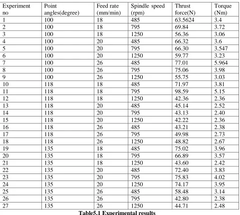
5. RESULTS AND DISCUSSION
Drilling tests were conducted to evaluate the effect of cutting parameters on
torque and thrust force and tabulated in table 5.1
Experiment no Point angles(degree) Feed rate (mm/min)
Spindle speed (rpm)
Thrust force(N)
Torque (Nm)
1 100 18 485 63.5624 3.4
2 100 18 795 69.84 3.72
3 100 18 1250 56.36 3.06
4 100 20 485 66.32 3.6
5 100 20 795 66.30 3.547
6 100 20 1250 59.77 3.23
7 100 26 485 77.01 5.964
8 100 26 795 75.06 3.98
9 100 26 1250 55.75 3.03
10 118 18 485 71.97 3.81
11 118 18 795 98.59 5.15
12 118 18 1250 42.36 2.36
13 118 20 485 45.14 2.52
14 118 20 795 43.13 2.40
15 118 20 1250 42.22 2.36
16 118 26 485 43.21 2.38
17 118 26 795 49.98 2.73
18 118 26 1250 48.82 2.67
19 135 18 485 75.02 3.96
20 135 18 795 66.89 3.57
21 135 18 1250 43.60 2.42
22 135 20 485 72.40 3.83
23 135 20 795 75.83 4.02
24 135 20 1250 74.17 3.95
25 135 26 485 58.48 3.14
26 135 26 795 42.80 2.38
27 135 26 1250 44.71 2.48
Table5.1 Experimental results
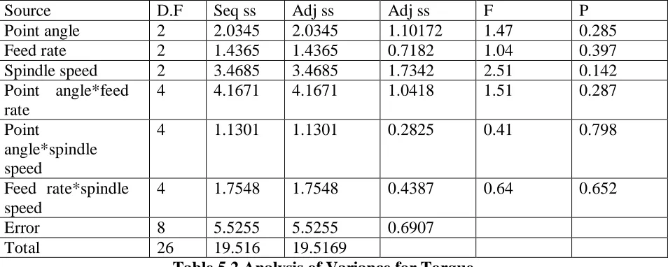
5.1 Analysis of Variance for Torque:
Table 5.2 presents the results of ANOVA for torque. It is
observed from the table the spindle speed is significant parameter for the torque. However
F-test decides whether the parameters significantly different. A larger value F shows the greater
[image:7.612.67.548.94.524.2]Source D.F Seq ss Adj ss Adj ss F P
Point angle 2 2.0345 2.0345 1.10172 1.47 0.285
Feed rate 2 1.4365 1.4365 0.7182 1.04 0.397
Spindle speed 2 3.4685 3.4685 1.7342 2.51 0.142
Point angle*feed rate
4 4.1671 4.1671 1.0418 1.51 0.287
Point
angle*spindle speed
4 1.1301 1.1301 0.2825 0.41 0.798
Feed rate*spindle speed
4 1.7548 1.7548 0.4387 0.64 0.652
Error 8 5.5255 5.5255 0.6907
Total 26 19.516 19.5169
Table 5.2 Analysis of Variance for Torque
5.2 Analysis of Variance for Thrust Force
Table 5.3 presents the results of ANOVA for torque. It is
observed from the table the spindle speed is significant parameter for the thrust force. However
F-test decides whether the parameters significantly different. A larger value F shows the
greater impact on the machining performance characteristics
Source D.F Seq ss Adj ss Adj ns F P
Point angle 2 781.6 781.6 390.8 2.69 0.128
Feed rate 2 894.7 894.7 447.3 3.08 0.102
Spindle speed 2 827.0 827.0 413.5 2.84 0.117
Point angle*feed rate
4 1234.9 1234.9 308.5 2.12 0.169
Point
angle*spindle speed
4 393.5 393.5 98.4 0.68 0.627
Feed rate*spindle speed
4 963.0 963.0 240.8 1.66 0.252
Error 8 1163.1 1163.1 145.4
Total 26 6257.8 6257.8
Table 5.3 Analysis of Variance for Thrust Force
5.3 Main effect plots analysis for torque:
The analysis is made with the help of a software package MINITAB 16. The
main effect plots are shown in fig.4. These show the variation of response with the three
[image:8.612.69.546.36.227.2]value of each parameter at three level and y- axis the response value. Horizontal line indicates
the mean value of the response. The main effects plots are used to determine the optimal design
conditions to obtain the optimum torque.
135 118 100 3.6 3.4 3.2 3.0 2.8
26 20 18
1250 795 485 3.6 3.4 3.2 3.0 2.8
point angle
M
ea
n
feed rate
spindle speed
mian effects
[image:9.612.312.530.117.256.2][image:9.612.79.526.307.457.2]
Fig 5.1 Main effects plots for torque Fig 5.2 Main effects plots for thrust force
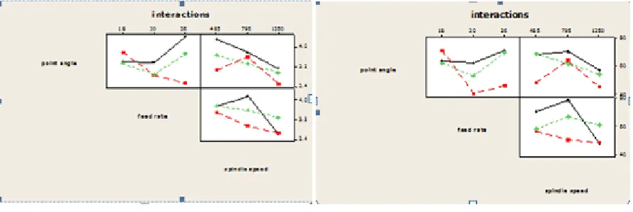
Fig 5.3 Interaction effects plots for torque Fig 5.4 Interaction effects plots for thrust force.
5.4 Main effect plots analysis for thrust force:
The analysis is made with the help of a software package MINITAB 16. The
main effect plots are shown in fig.4. These show the variation of response with the three
parameters i.e. point angle, Spindle speed and feed separately. In the plots, x axis indicate the
value of each parameter at three level and y- axis the response value. Horizontal line indicates
the mean value of the response. The main effects plots are used to determine the optimal design
conditions to obtain the optimum thrust force.
5.5 Interaction effects for torque and thrust force:
CONCLUSION
This paper presents the optimization of cutting process parameters namely, point angle, feed
rate and spindle speed in drilling of hybrid fiber reinforced polymer (HFRP) composites using
the full factorial and ANOVA analysis. The conclusions drawn from this work are as follows:
The optimum process parameters in the drilling of hybrid fiber
reinforced polymer (HFRP) composites are:
Point angle 118 , feed rate at 20 mm/min and spindle speed at
1250 rpm thrust force and torque are found to be optimum
The ANOVA results reveal that feed rate is most significant
influencing on the thrust force
The ANOVA results reveal that spindle speed is most significant
influencing on the torque
References
1. C. Dong, and I.J. Davies, Mat. & Design, 37, 450-457 (2012)
2. Desh Bandhu, Sandeepsingh Sangwan and Mukeshverma “optimization of drilling
parameter and surface roughness using different tool material by drilling of CFRP composite
material” international journal of current engineering and technology (2014)
3.Vijayan Krishnaraj, A.Prabhukarthi and Arun Ramanadhan “optimization of machining
parameters at high speed drilling of CFRP laminates” journal of home page
:www.elsevier.com/locate/compositesb
4. Shunmughesh, Paneerselvam and Jospaul Thomas “ optimization of drilling parameters of
GFRP by using Grey Relational Analysis” international journal of research in engineering and
technology
5.Mohd Azuwan Moinser, Fiaz ahmed and Safian sharif “minimizing thrust force for HFRP
composite by optimize process parameters using the combination of ANOVA approach and
signal to noise ratio”owned by authors, published by EDP sciences (2014)
6. M.Ramesh, K.Palanikumar and K.Hemachandrareddy “experimental investigation and
analysis of machining characterstics in drilling hybrid –glass –sisal-jute fiber reinforced
polymer compiosites” 5th
international and 26th all india manufacturing technology design and
7. B,V.Kavad, A,B.Pandey,M.V.Tadvi and H.C.Jakharia “a review paper effect of drilling on GFRP” 2nd
international conference on innovations in automation and mechatronics
engineering (2014)
8. M.Saravanan, D.Ramalingham and G.Mani kandan “multi objective optimization of drilling parameters”
9. J.Babu and Tom sunny “optimization of process parameters in drilling of GFRP composites by an End mill” international journal of recent development in engineering and technology
(2013)
10. Vinod kumar.V and Venkateswarlu Ganta “optimization of process parameters in drilling
of GFRP composite by Taguchi method” journal of material research and technology (2014)
11. Suresh.N, Rajesh Kumar.S, Prakash.K and Venkatesan.T “study and optimization of drilling parameters in GFRP”international journal of innovative research in technology (2015)
12. Mechanics of Composite Materials-AK KAW
13. Mechanics of Composite Materials-Robert M Jones
14. www.compositeworld.com