A Monthly Double-Blind Peer Reviewed Refereed Open Access International e-Journal - Included in the International Serial Directories.
International Research Journal of Mathematics, Engineering and IT (IRJMEIT)
1 | P a g e International Research Journal of Mathematics, Engineering and IT Vol. 2, Issue 11, Nov 2015 IF- 2.868 ISSN: (2349-0322)
© Associated Asia Research Foundation (AARF)
Website: www.aarf.asiaEmail : [email protected] , [email protected]AXIAL VIBRATION OF A CANTILEVER BEAM WITH A TIP MASS
Oktay Demirdag
Civil Engineering Department, Pamukkale University, Turkey
ABSTRACT
In this study free axial vibration of a cantilever beam with a tip mass is analyzed. The
boundary conditions are written for the fixed end and the end with the tip mass after the
differential equation of motion is solved by separation of variables method. The frequency
values for the first three vibration modes of the beam are obtained for various values of
concentrated mass and presented in the tables. The frequency values for the concentrated
mass values of zero are also compared with the ones of cantilever beam without tip mass and
nearly the exact values are obtained with negligible error percentages.
Keywords: Axial vibration, Cantilever Beam, Tip Mass, Frequency 1. Introduction
In practice, the representation of a beam by a discrete model is an idealized model;
however, in fact, beams have continuously distributed mass and elasticity. Mostly, especially
for the axially vibration, beams are modeled as continuous systems having infinite number of
degreed of freedom [1-10].
In this study, the free vibration analysis of a uniform axially vibrating cantilever beam
with a tip mass is made. The differential equation of motion of the axially vibrating beam is
solved by separation of variables method [11] and the displacement function is obtained. The
boundary conditions are written for the fixed end and the tip mass. The natural frequencies
for the first three modes are obtained for the various values of the tip mass. The results
obtained for the tip mass value of zero are compared with the frequency values of the
cantilever beam without a tip mass. The axially vibrating beam considered in the study is
A Monthly Double-Blind Peer Reviewed Refereed Open Access International e-Journal - Included in the International Serial Directories.
International Research Journal of Mathematics, Engineering and IT (IRJMEIT)
2 | P a g e
2. Solution of Equation of Motion for an Axıally Vıbratıng Beam
An axially vibrating beam, given in Figure.1, with the distributed mass m, the length
L, the modulus of elasticity E, the cross-section area A and the axial rigidity AE has a
dimensional differential equation of motion for free vibration as [12]
m, L, AE u(x,t)
x
Figure 1: An Axially Vibrating Beam
𝜕2𝑢(𝑥,𝑡)
𝜕𝑥2
−
𝑚 𝐴𝐸
𝜕2𝑢 𝑥,𝑡
𝜕𝑡2
= 0
(1)
where u(x,t) is the displacement function of the beam in terms of both displacement x and
time t. Application of the separation of variables method to Eq. (1) as in the form of Eq. (2) is
commonly used in vibration analysis of beams.
𝑢(𝑥, 𝑡) = 𝑋 𝑥 . 𝑇 𝑡 = 𝑋 𝑥 . [𝐴. sin 𝑡 + 𝐵. cos 𝑡 ]
(2)
In Eq. (2), X(x) is the eigenfunction named as shape function, T(t) is time function, is the
eigenvalue of the solution named as natural frequency and A, B are constants.
The derivatives used in Eq. (1) can, therefore, be written as
2𝑢 𝑥,𝑡
𝑥2 = 𝑢′′ 𝑥, 𝑡 = 𝑋′′ 𝑥 . 𝐴. sin 𝑡 + 𝐵. cos 𝑡 = 𝑋′′ 𝑥 . 𝑇 𝑡
(3)
2𝑢 𝑥,𝑡
𝑡2 = 𝑢 𝑥, 𝑡 = 𝑋 𝑥 . (−2) 𝐴. sin 𝑡 + 𝐵. cos 𝑡 = −2. 𝑋 𝑥 . 𝑇 𝑡
(4)
where (//) and (
¨
) denote the second order derivative due to x and t, respectively. Substitutionof Eq. (3) and Eq. (4) in Eq. (1) gives the governing equation of motion in the form as
𝑋′′ 𝑥 . 𝑇 𝑡 +𝑚2
AE 𝑋 𝑥 . 𝑇 𝑡 = 0 𝑋
′′ 𝑥 +𝑚2
AE 𝑋 𝑥 = 0 0 ≤ 𝑥 ≤ 𝐿
(5)
for
𝛼
2=
𝑚2
AE 𝑋′′ 𝑥 + 𝛼2𝑋 𝑥 = 0
A Monthly Double-Blind Peer Reviewed Refereed Open Access International e-Journal - Included in the International Serial Directories.
International Research Journal of Mathematics, Engineering and IT (IRJMEIT)
3 | P a g e
The characteristic equation and the solution of Eq. (6) is given as follows as D being d/dz:
𝐷2+ 𝛼2 = 0 → 𝐷
1,2 = ±𝑖𝛼 (7)
𝑋(𝑥) = 𝐶1. sin 𝛼𝑥 + 𝐶2. cos 𝛼𝑥 (8)
Eq. (8) gives the shape function of the axially vibrating beam due to the displacement
variable, x. Therefore, from Eq. (2), the displacement function of the axially vibrating beam
has the form of Eq. (9).
𝑢 𝑥, 𝑡 = 𝑋 𝑥 . 𝑇 𝑡 = 𝐶1. 𝑠𝑖𝑛 𝛼𝑥 + 𝐶2. 𝑐𝑜𝑠 𝛼𝑥 . 𝑇(𝑡)
(9)
3. Boundary Conditions
m, L, AE
x=0 x=L
M
Figure 2: Axially Vibrating a Cantilever Beam with a Tip Mass
Two boundary conditions have to be written for the cantilever beam with a tip mass in
Figure.2 since two integration constants (C1, C2) are obtained in the solution of second order
differential equation of motion. The boundary conditions written for the left and the right
ends of axially vibrating beam are given, respectively, as [13]
for x=0 𝑢 𝑥 = 0, 𝑡 = 0
(10)
for x=L 𝑁 𝑥 = 𝐿, 𝑡 = 𝐴𝐸𝑢′ 𝑥 = 𝐿, 𝑡 = −𝑀. 𝑢 (𝑥 = 𝐿, 𝑡)
(11)
where M is the tip mass value and N(x,t) is the axial force. If Eq. (9) and its derivative are
substituted into Eq. (10) and Eq. (11) one gets the following relation between the coefficient
matrix and the integration constants.
𝑘 . 𝐶 = 0; ∝. cos ∝ 𝐿 −∝𝑀2. sin(∝ 𝐿) . 𝐶
1 = 0
(12)
𝑘 = ∝. cos ∝ 𝐿 −∝𝑀2 . sin(∝ 𝐿) = 0
A Monthly Double-Blind Peer Reviewed Refereed Open Access International e-Journal - Included in the International Serial Directories.
International Research Journal of Mathematics, Engineering and IT (IRJMEIT)
4 | P a g e
where ∝𝑀2 =𝑀.𝜔 2
𝐴𝐸 . For non-trivial solution equating the determinant of the coefficient matrix
of Eq. (12) to zero, as in Eq. (13), will give the eigenfrequencies of the axially vibrating
cantilever beam with a tip mass. These frequencies are computed by a program written by the
author considering the secant method [14].
4. Numerical Analysis
The first three natural frequencies of the axially vibrating cantilever beam with a tip
mass are calculated for M values of 0, 10-10, 10-9, 10-8, 10-6, 10-4, 10-2, 10-1, 100, 101 and 102,
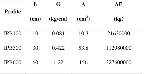
the beam length of L=1 m. and the modulus of elasticity of E=2100000 kg/cm2. IPB-100,
IPB-300 and IPB-600 profiles are used for numerical analysis with the mechanical properties
given in Table 1 where h is height, G is weight per length, A is cross-section area and AE is
axial rigidity of the corresponding profile. The distributed mass of the beam m is calculated
[image:4.595.148.452.379.536.2]from G/g as g being the acceleration of gravity with the value of 981 cm/sn2.
Table 1: The Mechanical Properties of the Profiles Used in This Study
Profile
h
(cm)
G
(kg/cm)
A
(cm2)
AE
(kg)
IPB100 10 0.081 10.3 21630000
IPB300 30 0.422 53.8 112980000
IPB600 60 1.22 156 327600000
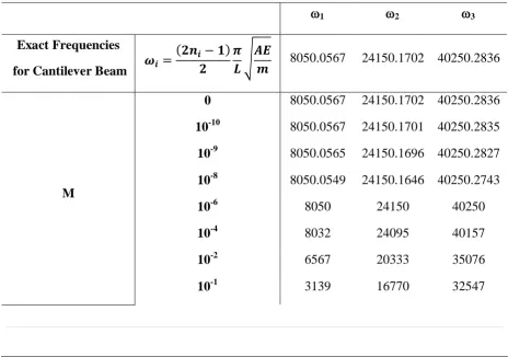
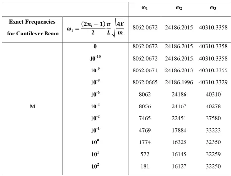
The frequency values computed due to different values of the tip mass are presented
in Table 2, Table 3 and Table 4 for, respectively, IPB-100, IPB-300 and IPB-600. The
frequency values obtained for M=0 are compared with the exact frequency values obtained
A Monthly Double-Blind Peer Reviewed Refereed Open Access International e-Journal - Included in the International Serial Directories.
International Research Journal of Mathematics, Engineering and IT (IRJMEIT)
[image:5.595.66.531.59.403.2]5 | P a g e
Table 2: Frequencies Computed for Different Values of the Tip Mass for IPB-100
1 2 3
Exact Frequencies
for Cantilever Beam 𝝎𝒊 =
𝟐𝒏𝒊− 𝟏
𝟐 𝝅 𝑳
𝑨𝑬
𝒎 8039.7053 24119.1160 40198.5266
M
0 8039.7053 24119.1160 40198.5266 10-10 8039.7052 24119.1157 40198.5261 10-9 8039.7044 24119.1131 40198.5218 10-8 8039.6956 24119.0868 40198.4779
10-6 8039 24117 40194
10-4 7944 23831 39719
10-2 4099 17306 32815
10-1 1451 16213 32226
100 465 16093 32166
101 148 16081 32160
[image:5.595.65.530.440.766.2]102 47 16080 32159
Table 3: Frequencies Computed for Different Values of the Tip Mass for IPB-300
1 2 3
Exact Frequencies
for Cantilever Beam 𝝎𝒊 =
𝟐𝒏𝒊− 𝟏
𝟐 𝝅 𝑳
𝑨𝑬
𝒎 8050.0567 24150.1702 40250.2836
M
0 8050.0567 24150.1702 40250.2836 10-10 8050.0567 24150.1701 40250.2835 10-9 8050.0565 24150.1696 40250.2827 10-8 8050.0549 24150.1646 40250.2743
10-6 8050 24150 40250
10-4 8032 24095 40157
10-2 6567 20333 35076
A Monthly Double-Blind Peer Reviewed Refereed Open Access International e-Journal - Included in the International Serial Directories.
International Research Journal of Mathematics, Engineering and IT (IRJMEIT)
6 | P a g e
100 1056 16170 32236
101 336 16108 32204
[image:6.595.62.530.140.497.2]102 107 16770 32201
Table 4: Frequencies Computed for Different Values of the Tip Mass for IPB-600
1 2 3
Exact Frequencies
for Cantilever Beam 𝝎𝒊 =
𝟐𝒏𝒊− 𝟏
𝟐 𝝅 𝑳
𝑨𝑬
𝒎 8062.0672 24186.2015 40310.3358
M
0 8062.0672 24186.2015 40310.3358 10-10 8062.0672 24186.2015 40310.3358 10-9 8062.0671 24186.2013 40310.3355 10-8 8062.0665 24186.1996 40310.3329
10-6 8062 24186 40310
10-4 8056 24167 40278
10-2 7465 22451 37580
10-1 4769 17884 33223
100 1774 16325 32350
101 572 16145 32259
102 181 16127 32250
5. Conclusions
In this study free axial vibration of a cantilever beam with a tip mass is made. The
natural frequency values are obtained for different values of the tip mass and presented in
tables. It can be seen from Tables 2, 3 and 4 that as the tip mass values increase from zero
through a value of 10-6 for all profiles considered in this study the frequency values gently
decrease, however, after the mentioned values the frequency values begin to decrease
dramatically and rapidly. Increasing the height of the beam section causes an increase in
A Monthly Double-Blind Peer Reviewed Refereed Open Access International e-Journal - Included in the International Serial Directories.
International Research Journal of Mathematics, Engineering and IT (IRJMEIT)
7 | P a g e
References
1. A.J. Wilson and P.J. Myers, The Longitudinal Vibrations of an Elastic Cylinder
Under Large Axial and Normal Tractions, International Journal of Solids and
Structures, 29(24), 1992, 3153-3168.
2. Q.S. Li, G.Q. Li and D.K. Liu, Exact Solutions for Longitudinal Vibrations of Rods
Coupled by Translational Springs, International Journal of Mechanical Scienses,
42(6), 2000, 1135-1152.
3. B.M. Kumar and R.I. Sujith, Exact Solutions for the Longitudinal Vibration of
Non-Uniform Rods, Journal of Sound and Vibration, 207(5), 1997, 721-729.
4. M. Rumerman and S. Raynor, Natural Frequencies of Finite Circular Cylinders in
Axially Symmetric Longitudinal Vibration, Journal of Sound and Vibration, 15(4),
1971, 529-543.
5. W. Surnelka, R. Zaera and J. Fernandez-Saez, A Theoretical Analysis of the Free
Axial Vibrations of Non-Local Rods with Fractional Continuum Mechanics,
Meccanica, 2015, in press.
6. O. Demirdag and B. Yildirim, Dimensionless Analysis of Axially Vibrating Beams,
Journal of Multidisciplinary Engineering Science and Technology, 2(8), 2015,
2207-2209.
7. O. Demirdag, Axial Vibration of Elastically Supported Beams, GE_International
Journal of Engineering Research, in-press, November, 2015.
8. O. Demirdag, Axial Vibration of Uniform Beams with Tip Masses, GE_International
Journal of Engineering Research, in-press, November, 2015
9. O. Demirdag, Dimensionless Free Vibration Analysis of Axially Vibrating Beams
with Tip Masses, Journal of Multidisciplinary Engineering Science Studies, in-press,
November, 2015
10.O. Demirdag, Dimensionless Analysis of Axially Vibrating Elastically Supported
Beams, Journal of Multidisciplinary Engineering Science Studies, in-press,
November, 2015
11.O. Demirdag, Free Vibration of Elastically Supported Timoshenko Columns with
Attached Masses by Transfer Matrix and Finite Element Methods, Sadhana, 31(1),
A Monthly Double-Blind Peer Reviewed Refereed Open Access International e-Journal - Included in the International Serial Directories.
International Research Journal of Mathematics, Engineering and IT (IRJMEIT)
8 | P a g e
12.J.J. Tuma and F.Y. Cheng, Theory and problems of dynamic structural analysis
(Schaum’s Outline Series, USA: McGraw-Hill, Inc., 1983).
13.V. Yerlici and H. Lus, Introduction to structural dynamics (Istanbul, Bogazici
University Publishing, Turkey, 2007 (in Turkish)).
14.K.H. Low, A Comprehensive Approach for the Eigenproblem of Beams With