Operating Instruction Manual
DTM for Hilscher PROFINET IO-Controller Devices
Configuration of Hilscher Controller Devices
Table of Contents
1
INTRODUCTION...6
1.1
About this Manual ...6
1.1.1
Descriptions of the Dialog Panes ...6
1.1.2
Online Help...6
1.1.3
List of Revisions ...7
1.1.4
Conventions in this Manual ...8
1.2
Legal Notes...9
1.2.1
Copyright ...9
1.2.2
Important Notes ...9
1.2.3
Exclusion of Liability ...10
1.2.4
Warranty ...10
1.2.5
Export Regulations ...11
1.2.6
Registered Trademarks ...11
1.3
About PROFINET IO-Controller DTM ...12
1.3.1
Requirements ...12
1.4
Dialog Structure of the PROFINET IO-Controller DTM...13
1.4.1
General Device Information...14
1.4.2
Navigation Area ...14
1.4.3
Dialog Panes ...15
1.4.4
OK, Cancel, Apply and Help...16
1.4.5
Table Lines ...16
1.4.6
Status Bar...17
2
GETTING STARTED...18
2.1
Configuration Steps ...18
3
SETTINGS ...23
3.1
Overview Settings...23
3.2
Settings for Driver and Device Assignment ...24
3.3
Driver ...26
3.3.1
Verify or adapt Driver Settings ...26
3.3.2
cifX Device Driver ...28
3.3.3
netX Driver...28
3.3.4
Configuring netX Driver ...29
3.3.5
netX Driver - USB/RS232 Connection...30
3.3.6
netX Driver - TCP/IP Connection ...32
3.7
Ethernet Devices ...47
3.7.1
Overview Ethernet Devices ...47
3.7.2
Selecting Network Devices for Scan ...48
3.7.3
Searching and selecting Devices ...49
3.7.4
Configuring Device ...52
4
CONFIGURATION ...62
4.1
Overview Configuration ...62
4.2
Configuring Device Parameters ...63
4.3
Controller Network Settings ...66
4.4
Device Table...67
4.5
IP Address Table ...68
4.5.1
Set the IP Settings of the PROFINET IO-Device Station ...69
4.6
Process Data ...70
4.7
Address Table...71
4.7.1
Auto Addressing, Display Mode, CSV Export ...72
4.7.2
Inputs / Outputs ...73
4.8
FSU/Port-Settings...75
4.9
Stations Timing ...77
4.9.1
Name of Station...77
4.10
Controller Settings ...78
4.10.1
Start of Bus Communication...79
4.10.2
Application Monitoring ...79
4.10.3
Module Alignment...80
4.10.4
Port Settings ...81
4.10.5
IO State Information ...82
5
ONLINE FUNCTIONS ...83
5.1
Connecting/Disconnecting Device ...83
5.2
‘Network Scan’ and ‘Upload’ ...85
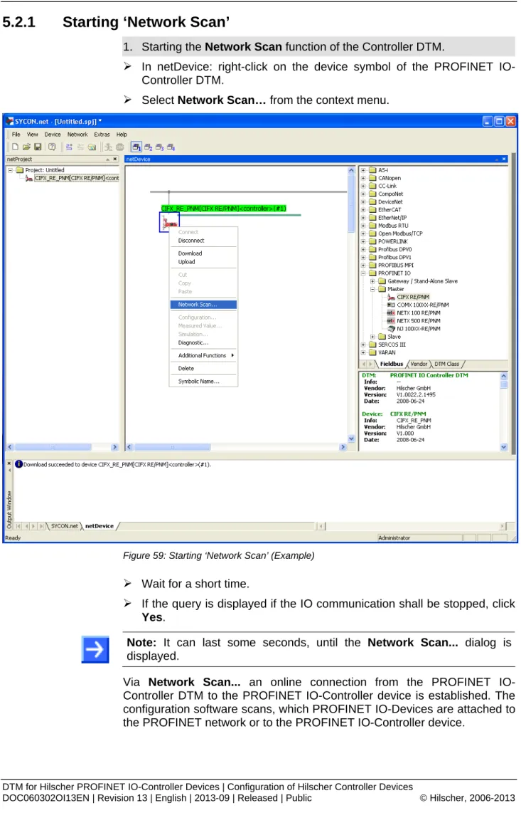
5.2.1
Starting ‘Network Scan’ ...86
5.2.2
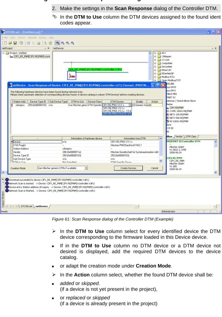
Settings in the Scan Response Dialog of the Controller DTM ...88
5.2.3
Description on the Scan Response dialog of the Controller DTM...89
5.2.4
Creating Devices ...91
5.2.5
Assigning IP Address and Networkmask of a Device ...91
5.2.6
Download to the PROFINET IO-Controller Device ...95
5.2.7
Running ‘Upload’ and generating Module Configuration...96
5.2.8
Download to the PROFINET IO-Controller Device ...99
5.5.4
How to order a License ...107
5.5.5
Selecting License(s) ...107
5.5.6
Ordering Data ...108
5.5.7
Ordering the License ...110
5.5.8
How to get the License and transfer it to the Device...115
6
DIAGNOSIS ...116
6.1
Overview Diagnosis ...116
6.2
General Diagnosis ...117
6.3
Master Diagnosis ...119
6.4
Firmware Diagnosis ...120
7
EXTENDED DIAGNOSIS ...121
7.1
Overview Extended Diagnosis ...121
7.2
Task Information ...123
7.3
IniBatch Status...124
7.4
General Diagnosis Information ...125
7.5
T_PNIO_EDD ...126
7.5.1
Extended Diagnosis Information ...126
7.5.2
XMAC Diagnosis Structure...127
7.6
T_PNIO_ACP ...128
7.6.1
Extended Diagnosis Information ...128
7.7
T_PNIO_DCP ...129
7.7.1
Extended Diagnosis Information ...129
7.8
T_PNIO_MGT ...130
7.8.1
Extended Diagnosis Information ...130
7.9
TCP_UDP ...131
7.9.1
IP Information ...131
7.9.2
IP Packet Counter ...132
7.9.3
TCP_UDP Information...132
7.10
T_RPC ...133
7.10.1
Extended Diagnosis Information ...133
7.11
T_PNIO_CMCTL ...134
7.11.1
Extended Diagnosis Information ...134
7.12
T_PNIO_APCTL ...135
7.12.1
Extended Diagnosis Information ...135
7.13
T_PNIO_APCFG ...136
8.3
IO Monitor ...141
8.4
Process Image Monitor ...142
9
ERROR CODES...144
9.1
Error Code Definition ...144
9.2
Overview Error Codes ...145
9.3
General Hardware Error Codes ...146
9.3.1
RCX General Task Errors ...146
9.3.2
RCX Common Status & Errors Codes ...147
9.3.3
RCX Status & Error Codes...148
9.4
Status /Error Codes PROFINET IO Controller...149
9.4.1
PNIO APCTL Status/Error Codes ...149
9.4.2
PNIO APCFG Status/Error Codes...151
9.4.3
PNIO CTL Status/Error Codes ...153
9.4.4
PNIO CTL Diagnosis-Codes ...163
9.4.5
RPC Task Status/Error Codes ...165
9.4.6
RPC Task Diagnostic Codes...168
9.4.7
Other relevant PNIO Status/Error Codes ...168
9.5
ODM Error Codes ...171
9.5.1
General ODM Error Codes ...171
9.5.2
General ODM Driver Error Codes ...172
9.5.3
cifX Driver Specific ODM Error Codes ...173
9.6
Error Codes cifX Device Driver and netX Driver ...176
9.6.1
Generic Error Codes...176
9.6.2
Generic Driver Error Codes...177
9.6.3
Generic Device Error Codes ...178
9.7
Error Codes netX Driver ...179
9.7.1
CIFX API Transport Error Codes...179
9.7.2
CIFX API Transport Header State Error Codes ...179
9.8
ODM Error Codes DBM V4...180
10
APPENDIX ...184
10.1
User Rights ...184
10.1.1
Settings...184
10.1.2
Configuration ...184
10.2
References ...185
10.3
List of Figures ...185
10.4
List of Tables ...187
10.5
Glossary...190
1 Introduction
1.1
About this Manual
This manual provides information on how to set and configure the device
parameters of a netX based PROFINET IO-Controller device using the
PROFINET IO-Controller DTM, and what can be read from the diagnosis
panes.
1.1.1
Descriptions of the Dialog Panes
The table below gives an overview for the individual dialog panes
descriptions:
Section Subsection Page
Settings Overview Settings 23
Driver 26
Device Assignment 35 Firmware Download 41
Licenses 103
Ethernet Devices 47 Configuration Overview Configuration 62 Controller Network Settings 66
Device Table 67 IP Address Table 68 Process Data 70 Address Table 71 FSU/Port-Settings 75 Stations Timing 77 Controller Settings 78
Diagnosis Overview Diagnosis 116
General Diagnosis 117 Master Diagnosis 119 Firmware Diagnosis 120 Extended Diagnosis Overview Extended Diagnosis 121
Tools Overview Tools 137
Packet Monitor 138
IO Monitor 141
Process Image Monitor 142 Table 1: Descriptions Dialog Pages
1.1.2 Online
Help
The PROFINET IO-Controller DTM contains an integrated online help
facility.
1.1.3
List of Revisions
In-dex
Date Version Component Chapter Revision
12 12-07-30 1.22.x.x PNIOControllerDTM.dll PNIOControllerGUI.ocx All, 1.3.1, 2.1, 4.7, 4.10.5, 5.2 Revised;
Section Requirements updated.
Sections Configuration Steps and Address Table updated.
Section IO State Information added,
Section ‘Network Scan’ and ‘Upload’revised and completed. 13 13-02-12 1.25.x.x, 1.25.x.x PNIOControllerDTM.dll PNIOControllerGUI.ocx 1.3.1, 2.1, 3.2, 3.3, 3.5, 3.6, 4.10.5 ; 8.4
Section Licensing added.
sections Configuration Steps, Settings for Driver and Device Assignment and Driver updated.
Section Firmware Download updated. Section Requirements updated. Section IO State Information updated. Section Process Image Monitor added. Table 2: List of Revisions
1.1.4
Conventions in this Manual
Notes, operation instructions and results of operation steps are marked as
follows:
Notes
Important:
<important note>
Note:
<note>
<note, where to find further information>
Operation Instructions
1. <instruction>
2. <instruction>
or
<instruction>
Results
<result>
Note:
The PROFINET IO specification defines the designations
"Controller" instead of "Master" and "Device" instead of "Slave". In this
manual "Controller" and "Device" are used with the PROFINET IO device
or the DTM. In connection with general questions about the Master or the
Slave functionality, the terms "Master" and "Slave" are used, as in the
network configuration on the Master bus line, the „Stand-Alone-Slave“, the
Master diagnosis or the Master license.
Positions in Figures
The
Positions
,
,
...
or
,
,
...
or
,
,
...
refer to the
figure used in that section. If the numbers reference to a section outside the
current section then a cross reference to that section and figure is
indicated.
1.2
Legal Notes
1.2.1 Copyright
© Hilscher, 2006-2013, Hilscher Gesellschaft für Systemautomation mbH
All rights reserved.
The images, photographs and texts in the accompanying material (user
manual, accompanying texts, documentation, etc.) are protected by
German and international copyright law as well as international trade and
protection provisions. You are not authorized to duplicate these in whole or
in part using technical or mechanical methods (printing, photocopying or
other methods), to manipulate or transfer using electronic systems without
prior written consent. You are not permitted to make changes to copyright
notices, markings, trademarks or ownership declarations. The included
diagrams do not take the patent situation into account. The company
names and product descriptions included in this document may be
trademarks or brands of the respective owners and may be trademarked or
patented. Any form of further use requires the explicit consent of the
respective rights owner.
1.2.2 Important
Notes
The user manual, accompanying texts and the documentation were created
for the use of the products by qualified experts, however, errors cannot be
ruled out. For this reason, no guarantee can be made and neither juristic
responsibility for erroneous information nor any liability can be assumed.
Descriptions, accompanying texts and documentation included in the user
manual do not present a guarantee nor any information about proper use
as stipulated in the contract or a warranted feature. It cannot be ruled out
that the user manual, the accompanying texts and the documentation do
not correspond exactly to the described features, standards or other data of
the delivered product. No warranty or guarantee regarding the correctness
or accuracy of the information is assumed.
We reserve the right to change our products and their specification as well
as related user manuals, accompanying texts and documentation at all
times and without advance notice, without obligation to report the change.
Changes will be included in future manuals and do not constitute any
obligations. There is no entitlement to revisions of delivered documents.
The manual delivered with the product applies.
Hilscher Gesellschaft für Systemautomation mbH is not liable under any
circumstances for direct, indirect, incidental or follow-on damage or loss of
earnings resulting from the use of the information contained in this
publication.
1.2.3
Exclusion of Liability
The software was produced and tested with utmost care by Hilscher
Gesellschaft für Systemautomation mbH and is made available as is. No
warranty can be assumed for the performance and flawlessness of the
software for all usage conditions and cases and for the results produced
when utilized by the user. Liability for any damages that may result from the
use of the hardware or software or related documents, is limited to cases of
intent or grossly negligent violation of significant contractual obligations.
Indemnity claims for the violation of significant contractual obligations are
limited to damages that are foreseeable and typical for this type of contract.
It is strictly prohibited to use the software in the following areas:
for military purposes or in weapon systems;
for the design, construction, maintenance or operation of nuclear
facilities;
in air traffic control systems, air traffic or air traffic communication
systems;
in life support systems;
in systems in which failures in the software could lead to personal injury
or injuries leading to death.
We inform you that the software was not developed for use in dangerous
environments requiring fail-proof control mechanisms. Use of the software
in such an environment occurs at your own risk. No liability is assumed for
damages or losses due to unauthorized use.
1.2.4 Warranty
Although the hardware and software was developed with utmost care and
tested intensively, Hilscher Gesellschaft für Systemautomation mbH does
not guarantee its suitability for any purpose not confirmed in writing. It
cannot be guaranteed that the hardware and software will meet your
requirements, that the use of the software operates without interruption and
that the software is free of errors. No guarantee is made regarding
infringements, violations of patents, rights of ownership or the freedom from
interference by third parties. No additional guarantees or assurances are
made regarding marketability, freedom of defect of title, integration or
usability for certain purposes unless they are required in accordance with
the law and cannot be limited. Warranty claims are limited to the right to
claim rectification.
1.2.5 Export
Regulations
The delivered product (including the technical data) is subject to export or
import laws as well as the associated regulations of different counters, in
particular those of Germany and the USA. The software may not be
exported to countries where this is prohibited by the United States Export
Administration Act and its additional provisions. You are obligated to
comply with the regulations at your personal responsibility. We wish to
inform you that you may require permission from state authorities to export,
re-export or import the product.
1.2.6 Registered
Trademarks
Windows
®XP, Windows
®Vista, Windows
®7 and Windows
®8 are
registered trademarks of Microsoft Corporation.
PROFINET
®is a registered trademark of PROFIBUS International,
Karlsruhe.
CODESYS
®is a registered trademark of 3S-Smart Software Solutions
GmbH, Deutschland.
All other mentioned trademarks are property of their respective legal
owners.
1.3
About PROFINET IO-Controller DTM
You can use the PROFINET IO-Controller DTM to configure the PROFINET
IO-Controller device within a FDT Framework.
1.3.1 Requirements
System Requirements
PC with 1 GHz processor or higher
Windows
®XP SP3, Windows
®Vista (32 bit) SP2, Windows
®7 (32 bit)
SP1, Windows
®7 (64 bit) SP1, Windows
®8 (32 bit) or Windows
®8 (64
bit)
Administrator privilege required for installation
Internet Explorer 5.5 or higher
RAM: min. 512 MByte, recommended 1024 MByte
Graphic resolution: min. 1024 x 768 pixel
Keyboard and Mouse
Note:
If the project file is saved and opened again or if it is used on
another PC, the system requirements must match. Particularly the DTM
must be installed on the used PC.
Restriction
Touch screen is not supported.
Requirements PROFINET IO-Controller DTM
To configure the PROFINET Controller device with the PROFINET
IO-Controller DTM the following requirements have to be accomplished:
Completed hardware installation of a netX based DTM-compatible
PROFINET IO-Controller device, inclusive loaded firmware, license and
loaded cifX configuration file
Installed FDT/DTM V 1.2 compliant frame application
Loaded DTM in the Device Catalog of the FTD Framework
Note:
If the PROFINET Controller DTM and the PROFINET
IO-Controller device are installed on the same PC, the
cifX Device Driver
must be installed on that PC, as you can connect the DTM to the device.
For more information to the hardware installation, please refer to the
corresponding
User Manual
of your device.
To get information on how to order and to download the license to the
device, please refer to section
Licenses
on page 103.
1.4
Dialog Structure of the PROFINET IO-Controller DTM
The graphical user interface of the DTM is composed of different areas and
elements listed hereafter:
1. A header area containing the
General Device Information
,
2. The
Navigation Area
(area on the left side),
3. The
Dialog Pane
(main area on the right side),
4.
OK
,
Cancel
,
Apply
,
Help
,
5. The
Status Line
containing information e. g. the online-state of the
DTM.
1.4.1
General Device Information
Parameter Meaning
IO Device Name of the device Vendor Vendor name of the device Device ID Identification number of the device Vendor ID Identification number of the vendor Table 3: General Device Information
1.4.2 Navigation
Area
The
Navigation Area
contains folders and subfolders to open the dialog
panes of the DTM.
Figure 2: Navigation Area
Select the required folder and subfolder.
The corresponding Dialog pane is displayed.
Hide / display Navigation
Hiding the navigation area (above right side). Openingthe navigation area (below left side).
1.4.3 Dialog
Panes
At the dialog pane the
Settings
,
Configuration
,
Diagnosis
/
Extended
Diagnosis
or the
Tools
panes are opened via the corresponding folder in
the navigation area.
Settings
Driver To establish a connection from the PROFINET Controller DTM to the PROFINET IO-Controller device, on the pane Driver you can verify if the default driver is checked and respectively check another driver or multiple drivers. For further information, refer to section Driver on page 26.
Device Assignment On the Device Assignment pane you select the device and assign the deviceto the driver. For further information, refer to section Device Assignment on page 35.
Firmware Download The dialog on the Firmware Download pane is used to load a new firmware into the device. A detailed description can be found in section Firmware Download on page 41.
Licensing Using the license dialog, you can order licenses for Master protocols or Utilities and download them to your device. A detailed description can be found in section Licenses on page103. Ethernet Devices The dialog on the Ethernet Devices pane is used to adjust the device name (=Name of
Station) or the IP address at Ethernet-capable devices or to use existing values therefore. A detailed description can be found in section Ethernet Devices on page 47.
Configuration
Controller Network Settings
The Controller Network Settings pane displays general PROFINET IO-Controller
information. Here you must set the name of station and the IP settings for the PROFINET IO-Controller. For further information, refer to section Controller Network Settings on page 66. Device Table The Device Table displays the list of all configured PROFINET IO-Device devices. Here you
must set the network name for the PROFINET IO-Device station. For further information, refer to section Device Table on page 67.
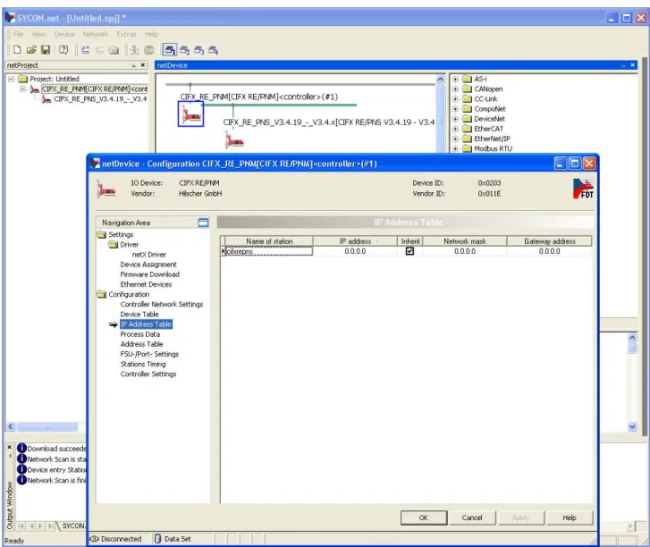
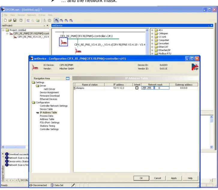
IP Address Table The IP Address Table pane displays communication data of the devices associated with the PROFINET IO-Controller. Here you must make the IP settings for the PROFINET IO-Device station. For further information, refer to section IP Address Table on page 68.
Process Data The Process Data pane serves for the PROFINET IO-Controller DTM as an external process data interface. For further information, refer to section Process Data on page 70.
Address Table The Address Table pane shows a list of all dpram addresses used in the process data image. Here you must set the address. For further information, refer to section Address Table on page 71.
FSU/Port Settings On the FSU/Port Settings pane you set in the PROFINET IO-Controller device, wether a PROFINET IO-Device must use a fast start up (FSU) connection to establish the the cyclic data exchange. For further information, refer to section FSU/Port-Settings on page 75. Stations Timing On the pane Stations Timing you can select or set station global and modularec settings. For
further information, refer to section Stations Timing on page 77.
Controller Settings At the Controller Settings pane device related settings can be made. For further information, refer to section Controller Settings on page 78 .
Diagnosis
Diagnosis/
Extended Diagnosis
At the Diagnosis panes information can be read for troubleshooting. For further information, refer to section Overview Diagnosis on page 116 or section Overview Extended Diagnosis on page 121.
Tools
Packet Monitor/ IO Monitor/ Process Image
Under Tools the Packet Monitor and the IO Monitor are provided for test and diagnosis purposes. For further information, refer to section Packet Monitor on page 138, section IO Monitor on page 141 or section Process Image Monitor on page 142.
Note:
Accessing the
Diagnosis
panes of the PROFINET IO-Controller
DTM requires an online connection from the PROFINET IO-Controller
DTM to the PROFINET IO-Controller device.
For further information, refer to section
Connecting/Disconnecting Device
on page 83.
1.4.4
OK, Cancel, Apply and Help
OK
,
Cancel
,
Apply
and
Help
you can use as described hereafter.
Meaning
OK To confirm your latest settings, click OK. All changed values will be applied on the frame application database.
The dialog then closes.
Cancel To cancel your latest changes, click Cancel.
Answer to the safety query Configuration data has been changed.Do you want to save the data?
by Yes, No or Cancel.
Yes: The changes are saved or the changed values are applied on the frame application database. The dialog then closes.
No: The changes are not saved or the changed values are not applied on the frame application database.
The dialog then closes.
Cancel: Back to the DTM.
Apply To confirm your latest settings, click Apply. All changed values will be applied on the frame application database.
The dialog remains opened.
Help To open the DTM online help, click Help. Table 5: OK, Cancel, Apply and Help
1.4.5 Table
Lines
In the DTM dialog pane table lines can be selected, inserted or deleted.
Meaning
To select the first line of a table use First Line.
To select the previous line of a table use Previous Line. To select the next line of a table use Next Line.
To select the last line of a table use Last Line.
Create a new Line inserts new lines into the table.
Delete selected Line deletes the selected line from the table. Table 6: Selecting, inserting, deleting Table Line
1.4.6 Status
Bar
The
Status Bar
displays information about the current state of the DTM.
The current activity, e.g. download, is signaled graphically via icons in the
status bar.
Figure 3: Status Bar – Status Fields 1 to 6
Status Field
Icon / Meaning
1 DTM Connection States
Connected: Icon closed = Device is online
Disconnected: Icon opened = Device is offline
2 Data Source States
Data set: The displayed data are read out from the instance data set (database).
Device: The displayed data are read out from the device.
3 States of the instance Date Set
Valid Modified: Parameter is changed (not equal to data source).
4 Changes directly made on the Device
Load/configure diagnosis parameters: Diagnosis is activated.
6 Device Diagnosis Status
Save operation succeeded: The save operation has been successful. Further messages due to successful handling of device data.
Firmware Download: Firmware Download is running
Save operation failed: The save operation has failed.
Further fail operation messages due to incorrect communication due to malfunction in the field device or its peripherals.
Table 7: Status Bar Icons [1]
Offline State
Save operation succeeded
Firmware Download
2 Getting
started
2.1
Configuration Steps
The following overview provides to you the step sequence on how to
configure a netX based PROFINET IO-Controller device with PROFINET
IO-Controller DTM as it is typical for many cases. At this time it is
presupposed that the hardware installation was done.
The overview lists all the steps in a compressed form. For detailed
descriptions of each step refer to the sections noted in the column
For
detailed information see section
.
# Step Short Description For detailed information
see section
Page
1 Add PROFINET IO-Device in the IO-Device Catalog
Add the Device in the Device Catalog by importing the device description file to the Device Catalog.
Depending of the FDT Container. For netDevice:
- Network > Import Device Descriptions.
(See Operating Instruction Manual netDevice and netProject)
-
2 Load device catalog Depending of the FDT Container: For netDevice:
- select Network > Device Catalog, - select Reload Catalog.
(See Operating Instruction Manual netDevice and netProject)
-
3 Create new project / Open existing project
Depending of the frame application. For the configuration software: - select File > New or File > Open.
(See Operating Instruction Manual of the Frame Application)
-
4 Insert Controller or Device into configuration
Depending of the FDT Container: For netDevice:
Important! In order to select the de-sired device in the device catalog, note the details about the DTM and the de-vice at the bottom of the window. When sorting by Fieldbus multiple devices with identical names by different vendors can be displayed.
- in the Device Catalog click to the Controller, - and insert the device via drag and drop
to the line in the network view,
- in the Device Catalog click to the Device, * - and insert the device via drag and drop
to the Controller bus line in the network view. (*This step won’t be necessary if the network structure is scanned automatically.
See step 17.)
(See Operating Instruction Manual netDevice and netProject)
-
5 Open the Controller DTM configuration dialog
Open the Controller DTM configuration dialog. - Double click to the device icon of the Controller.
- The Controller DTM configuration dialog is displayed.
6 Verify or adapt Driver Settings
In the Master DTM configuration dialog: - select Settings > Driver.
Note! For PC cards cifX the cifX Device Driver is preset as a default driver. For all the other Hilscher devices the netX Driver is preset as a default driver.
Use the cifX Device Driver if the PROFINET IO-Controller DTM is installed on the same PC as the PROFINET IO-Controller device. Use the netX Driver to establish a
USB, Serial (RS232) or TCP/IP connection from the PROFINET IO-Controller DTM to the PROFINET IO-Controller device.
The3SGateway Driver for netX (V3.x) is used only in relationship with CODESYS.
To search for devices you can check one or multiple drivers simultaneously. - Verify that the default driver is checked. - If necessary, check another driver or multiple drivers.
Settings for Driver and Device Assignment and
Driver
24
26
7 Configure Driver If you use the netX Driver, you respectively must configure it.
For netX Driver and communication via TCP/IP set the IP address of the device: - Select Settings > Driver > netX Driver > TCP Connection.
- Via add an IP range.
- Under IP Address enter the IP Address of the device or an IP range.
- Click Save.
Adjust the driver parameters netX Driver USB/RS232 only if they differ from the default settings.
Note!
The cifX Device Driver requires no configuration.
The configuration of the 3SGateway Driver for netX (V3.x) is carried out via the CODESYS surface.
Configuring netX Driver 29
8 Assign Controller device (with or without firmware)
Assign the deviceto this driver.
In the Controller DTM configuration dialog: - select Settings > Device Assignment, - select a Controller device (with or without firmware),
- therefore check the appropriate checkbox, - select Apply.
Selecting the Device (with or without firmware)
38
9 Select and download firmware
If not yet a firmware was loaded to the device. In the Controller DTM configuration dialog: - select Settings > Firmware Download, - select Browse..,
10 Assign Controller device once more (with firmware and system chanal) For repeated download this step is omitted.
In the Controller DTM configuration dialog: - select Settings > Device Assignment, - select Scan,
- select the Controller device (with loaded and defined system channel),
- therefore check the appropriate checkbox, - select Apply,
- close the Controller DTM configuration dialog via OK.
Selecting the Device once more (with Firmware)
39
11 Configuring Ethernet Device
In the Controller DTM configuration dialog: - select Settings > Ethernet Devices, - click Devices Online > Search devices, - under Devices Online click the line for the device to be configured.
- Respectively check Use Configuration of and select a device, the configuration of which shall be used.
- Set the device name (=Name of Station) newly or overtake it,
- click Set Name,
- set the IP address, subnet mask and gateway address newly or overtake them,
- click Set Address,
- click Search devices once more to display the newly adjusted current values,
- close the Controller DTM configuration dialog via OK.
Ethernet Devices 47
12 Configure Device* (*This step won’t be necessary if the network structure is scanned
automatically. See step 17.)
Configure the Device.
In the DTM device configuration dialog: - select Configuration > Moules,
- configure the PROFINET IO-Device modules, - select Configuration > Device Settings, - set the Device Settings.
- Close the DTM device configuration dialog via
OK.
(See Operating Instruction Manual DTM for
PROFINET IO-Devices) -
13 Configure Controller device
For Device device: Set Name of Station and
IP settings.
Configure the Controller device. - Double click to the device icon of the Controller.
In the Controller DTM configuration dialog: - select Configuration > Controller Network Settings,
- set the name of station for the Controller, - make the IP settings for the Controller, - select Configuration > Device Table, - select the PROFINET IO-Device required, - Enter the name of station of the PROFINET IO-Device station,
- select Configuration > IP Address Table, - Enter the IP settings of the PROFINET IO-Device station.
- select Configuration > Process data, - set symbolic names for the configured modules or signals.
- select Configuration > Address Table, - activate or deactivate auto addressing, - for manual addressing: enter the addresses, - select Configuration > FSU/Port-Settings, chose the FSU-Port settings. Therefore check
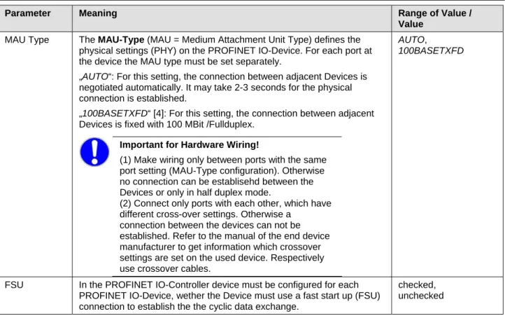
FSU for the appropriate device(s) and for each port set the MAU-Type.
Configuring Device Parameters Controller Network Settings Device Table IP Address Table Process Data Address Table FSU/Port-Settings 63 66 67 68 70 71 75
Port Settings for the Controller device and IOPS interface configuration).
- close the Controller DTM config. dialog via
OK.
-
14 Save project Depending of the frame application. For the configuration software: - select File > Save.
(See Operating Instruction Manual of the Frame Application)
-
15 Connect Controller device
Depending of the FDT Container. For netDevice:
- right click to the device icon of the Controller, - select Connect.
Connecting/Disconnecting Device
83
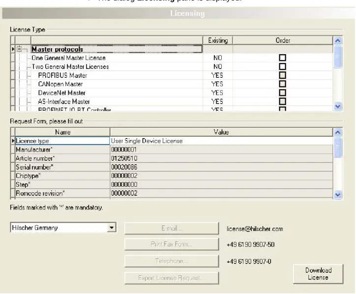
16 Licensing How to order licenses later and how to transfer them to the device.
Licenses 103
17 Download Configuration
Depending of the FDT Container. For netDevice:
- right click to the device icon of the Controller, - select Download.
Download Configuration 102
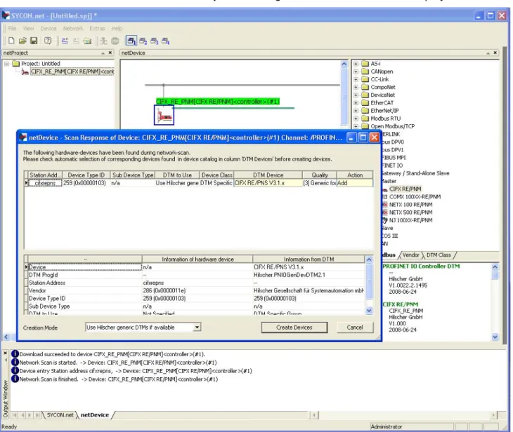
18 Network Scan / Upload
As an alternative to manually configure the Device, you can automatically scan the network structure by using the context menu Network Scan. Then confirm the query whether the module configuration of the Device shall be generated and download the configuration to the Controller device.
Important: For the generation of the module configuration, you first must manually assign the IP settings to the Device in the PROFINET IO Controller DTM.
Proceed the steps as follows: 1. Start the Network Scan function. 2. Make the settings in the Scan Response
dialog of the Master DTM. 3. Click Create devices.
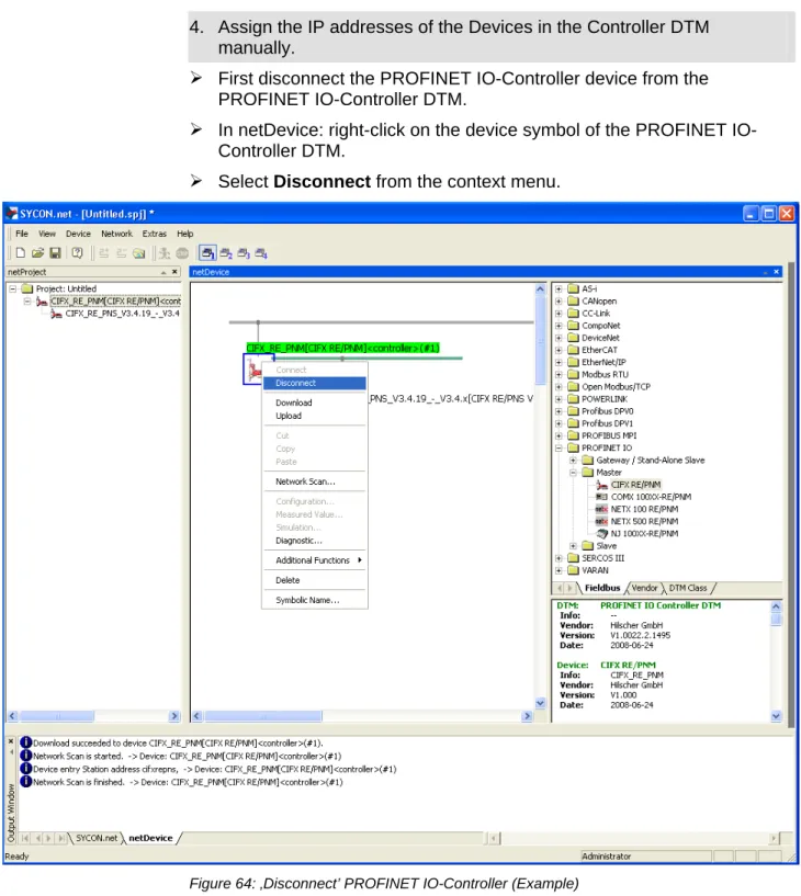
4. Assingn the IP address of the Device in the Controller DTM manually
5. Download of the configuration to the Controller device (Download).
6. Upload of the Device configuration and genere the module configuration.
7. Download the Device configuration to the Controller device (Download).
‘Network Scan’ and ‘Upload’
85
19 Diagnosis Depending of the FDT Container. For netDevice:
- right click to the device icon of the Controller, - select Diagnosis.
- The Controller DTM diagnosis dialog is displayed.
(1) Check whether the communication is OK:
Diagnosis > General Diagnosis > Device status"Communication" must be green! (2) "Communication" is green: Open thel IO Monitor and test the input or output data. (3) "Communication" is not green: Use Diagnosis and Extended diagnosis for
20 IO Monitor Depending of the FDT Container: For netDevice:
- right click to the device icon of the Controller, - select Diagnosis,
- select Tools > IO Monitor. - Check the input or output data, - close the IO Monitor dialog via OK.
IO Monitor 141
21 Disconnect Depending of the FDT Container. For netDevice:
- right click to the device icon of the Controller, - select Disconnect.
Connecting/Disconnecting Device
83
3 Settings
3.1
Overview Settings
Settings Dialog Panes
The table below gives an overview for the individual
Settings
dialog panes
descriptions:
PROFINET IO-Controller DTM Folder Name / Section Subsection Manual Page Driver 26Verify or adapt Driver Settings 26
cifX Device Driver 28
netX Driver 28
Configuring netX Driver 29
Device Assignment 35
Scanning for Devices 35
Scanning for all Devices or for suitable only 37 Selecting the Device (with or without firmware) 38 Selecting the Device once more (with Firmware) 39
Firmware Download 41
Navigation Area – Settings (Example) Additional drivers can be displayed.
Licenses 103
Table 9: Descriptions of the Dialog Panes Settings
Note:
To edit the
Settings
dialog panes you need
User Rights
for
“Maintenance”.
Notice the descriptions in the section
Settings for Driver and Device
Assignment on page 24.
To access to the online help with the descriptions of the drivers:
Select
Settings > Driver >
[
Name of the assigned driver
].
3.2
Settings for Driver and Device Assignment
The following steps are needed to establish a connection from the
PROFINET IO-Controller DTM to the PROFINET IO-Controller device:
Verify or adapt Driver Settings
Verify the Driver Settings and adapt them if necessary.
1. Open the DTM configuration dialog.
In the FDT container
netDevice
double click to the PROFINET
IO-Controller device icon.
2. Verify that the default driver is checked and respectively check another
or multiple drivers.
Select
Settings > Driver
.
Note!
For PC cards cifX the
cifX Device Driver
is preset as a default
driver. For all the other Hilscher devices the
netX Driver
is preset as a
default driver.
Use the
cifX Device Driver
if the PROFINET IO-Controller DTM is
installed on the same PC as the PROFINET IO-Controller device.
Use the
netX Driver
to establish a USB, Serial (RS232) or TCP/IP
connection from the PROFINET IO-Controller DTM to the PROFINET
IO-Controller device.
The
3SGateway Driver for netX (V3.x)
is used only in relationship with
CODESYS.
To search for devices on the network you can check one or multiple
drivers simultaneously.
Verify that the default driver for your device is checked.
If necessary, check another driver or multiple drivers.
Configure Driver
Note!
The
cifX Device Driver
requires no configuration.
The configuration of the
3SGateway Driver for netX (V3.x)
is carried
out via the CODESYS surface.
If you use the
netX Driver
, you respectively must configure it.
3. Configure
the
netX Driver
if necessary.
For the driver
netXDriver
an individual driver dialog window can be opened
where you can configure the driver.
Select
Settings > Driver
>
netX Driver
.
4. Scan for and select the devices (with or without firmware).
Select
Settings > Device Assignment
.
Under
Device selection
select
suitable only
or
all
and then
Scan
.
In the table check the required devices.
Select
Apply
.
Select and download the Firmware
5. If not yet a firmware was loaded to the device, select and download the
firmware.
Select
Settings > Firmware Download
.
Select and download the firmware via
Download
.
Select
Apply
.
6. Scan for and select the devices (with firmware and defined system
channel) once more.
For repeated download this step is omitted.
Select
Settings > Device Assignment
.
Select
Scan
.
In the table check the required devices.
7. Close the DTM configuration dialog via
OK
.
Connecting the Device
8. In
netDevice
put a right-click on the PROFINET IO-Controller device
icon.
9. Select
the
Connect
command from the context menu.
In the network view the device description at the device icon of the
Controller is displayed with a green colored background. The
PROFINET IO-Controller device now is connected to the PROFINET
IO-Controller DTM via an online connection.
Further Information
For descriptions about these steps refer to the sections following
here-after.
3.3
Driver
The
Driver
dialog pane displays the drivers to be used for a PROFINET
IO-Controller DTM to establish a device communication connection.
Note!
A
default driver
is set in the configuration software.
Figure 5: Default Driver ‚cifX Device Driver’ for PC cards cifX
Parameter Meaning
Driver Name of the driver (for more details see descriptions hereafter) Version ODMV3 Version of the respective driver
ID ID of the driver (driver identification)
Table 10: Driver Selection List Parameters
To establish a connection from the PROFINET IO-Controller DTM to the
PROFINET IO-Controller device, verify if the default driver is checked and
respectively check another driver or multiple drivers.
3.3.1
Verify or adapt Driver Settings
Proceed as follows:
1. Select
Settings > Driver
in the navigation area.
The
Driver
dialog pane is displayed with the available drivers and the
setting for the default driver.
Default Driver
(Pre-settings in the Configuration Software): For PC cards
cifX the
cifX Device Driver
is preset as a default driver. For all the other
Hilscher devices the
netX Driver
is preset as a default driver.
3. Respectively check another driver.
Note!
The driver used for the connection from the PROFINET
IO-Controller DTM to the PROFINET IO-IO-Controller device must be supported
by the device and must be available for the device.
Use the
cifX Device Driver
if the PROFINET IO-Controller DTM is
installed on the same PC as the PROFINET IO-Controller device.
Use the
netX Driver
to establish a USB, Serial (RS232) or TCP/IP
connection from the PROFINET IO-Controller DTM to the PROFINET
IO-Controller device.
The
3SGateway Driver for netX (V3.x)
is used only in relationship with
CODESYS. The version V3.x refers to the driver version defined by
3S-Smart Software Solutions GmbH.
Check the checkbox for the driver in the selection list.
4. Respectively check multiple drivers.
To search for devices on the network you can check multiple drivers
simultaneously.
3.3.2
cifX Device Driver
In the PROFINET IO Controller DTM for the
cifX Device Driver
no driver
dialog pane is available, since for the
cifX Device Driver
no driver settings
are required.
The
cifX Device Driver
will be used if the PROFINET IO Controller DTM is
installed in the same PC as the PROFINET IO Controller device.
Note:
To establish a connection from a DTM to a Controller device via the
cifX Device Driver
, the
cifX Device Driver
must be installed and the
driver must have access to the Controller device.
3.3.3 netX
Driver
The
netX Driver
is used to connect the DTM to the device via different
connection types. The DTM communicates with the device via an USB
connection, a serial (RS232) connection or a TCP/IP connection. The
netX
Driver
establishes
via the USB interface of the device and the USB port of the PC an USB
connection to the device,
via the RS232 interface of the device and the COM port of the PC a
serial connection (RS232) to the device
and via Ethernet a TCP/IP connection to the device.
To connect the DTM to the physical layer of the device the
netX Driver
software works in combination with the software components:
“USB/COM connector” for the USB connection and for the serial
connection (RS232) and
3.3.4 Configuring
netX
Driver
The following steps are required to configure the netX Driver:
USB/RS232 Connection
To set the driver parameters for an USB/RS232 connection note:
Note:
Adjust the driver parameters netX Driver USB/RS232 only if they
differ from the default settings. After saving the changed driver
parameters, these parameters are used for the device assignment when
scanning devices.
For setting the driver parameters for an USB connection or a serial
connection:
1. Select
Settings > Driver > netX Driver > USB/RS232 Connection
.
Set the driver netX Driver USB/RS232 parameters.
TCP/IP Connection
For setting the driver parameters for a TCP/IP connection:
1. Select
Settings > Driver > netX Driver > TCP Connection
.
2. Set IP Address of the device:
Add an IP Range via
Select IP Range
.
3. Under
IP Range Configuration
>
IP Address
enter the IP Address of
the device (
Use IP Range
is unchecked).
Or
4. Set IP Range:
Check
Use IP Range
.
Under
IP Range Configuration
>
IP Address
enter the start address
(left side) and the ending address of the IP scanning range (right side).
5. Click
Save
, to save the IP address or the IP range.
After saving the changed driver parameters, these parameters are used
for the device assignment when scanning devices.
3.3.5
netX Driver - USB/RS232 Connection
The communication from the DTM to the device via an
USB/RS232
Connection
is used when the DTM is installed on a PC and between the
PC and the device
an USB connection
or a serial connection (RS232) exists.
The DTM accesses the device via the USB interface or via the RS232
interface. This requires either to connect an USB port of the PC to the USB
interface of the device using an USB cable or to connect a physical COM
port of the PC to the RS232 interface of the device via a serial cable.
The
netX Driver
/
USB/RS232 Connection
supports all physical and
virtual COM ports available on the PC.
Via the RS232 interface or USB interface, the device is configured or
diagnosis is performed.
3.3.5.1
Driver Parameters for netX Driver - USB/RS232 Connection
The settings of the driver parameters for the USB/RS232 connection are
made via the
netX Driver / USB/RS232 Connection
configuration dialog.
Open
the
USB/RS232 Connection
dialog via navigation area
Settings
> Driver > netX Driver
.
Parameter Meaning Range of Value / Default Value Enable USB/RS232
Connector (Restart of ODM required)
checked: The netX Driver can communicate via the USB/RS232 interface.
unchecked: The netX Driver can not communicate via the USB/RS232 interface.
If the check mark for Enable USB/RS232 Connector is set or removed, then the ODM server must be restarted1, to make the new setting valid.
_______
1
Restart the ODM server via the ODMV3 Tray Application:
-In the foot line click on using the right mouse key. - In the context menu select Service > Start.
checked, unchecked; Default: unchecked
Select Port Depending on the COM ports (interfaces) available on the PC, they will be listed under Select Port.
COM 1 to COM N
Port Configuration
Disable Port checked: No connection.
unchecked: The netX Driver tries to establish a connection using the configured USB/RS232 interface.
checked,
unchecked (Default)
Baud rate Transfer rate: number of bits per second. The device must support the baud rate.
9.6, 19.2, 38.4, 57.6 or 115.2 [kBit/s];
Default (RS232): 115.2 [kBit/s]
Stop bits Number of stop bits sent after the transfer of the send data for synchronization purposes to the receiver.
Stop bit: 1, 1.5, 2; Default (RS232): 1
Send Timeout Maximum time before the transfer of the transmission data is canceled, when the send process fails, for example, because of the transfer buffer is full.
100 … 60.000 [ms]; Default (RS232 and USB): 1000 ms
Reset Timeout Maximum time for a device reset, including the re-initialization of the physical interface used for the communication.
100 … 60.000 [ms]; Default (RS232 and USB): 5000 ms
Byte size Number of bits per byte by byte specification 7 Bit, 8 Bit;
Default (RS232): 8 Bit
Parity In the error detection in data transmission using parity bits, "parity" describes the number of bits occupied with 1 in the transmitted information word.
No Parity: no parity bit
Odd Parity: The parity is "odd" if the number of bits occupied with 1 in the transmitted information word will be odd. Even parity: The parity is "even" if the number of bits occupied with 1 in the transmitted information word will be even.
Mark Parity: if the parity bit is always 1, this will be named mark-parity (the bit does not contain any information). Space Parity: if the parity bit always 0, this will be named space-parity (the bit represents an empty space).
No Parity, Odd Parity, Even Parity, Mark Parity, Space Parity; Default (RS232): No Parity
Keep Alive Timeout The "Keep Alive" mechanism is used to monitor whether the connection to the device is active. Connection errors are detected using a periodic heartbeat mechanism. The heartbeat mechanism will be initiated after the set time has elapsed if the communication has failed.
100 … 60.000 [ms]; Default (RS232 and USB): 2000 ms
3.3.6
netX Driver - TCP/IP Connection
The communication from the DTM to the device via a
TCP/IP Connection
is used in the following two typical applications:
Application 1: The device has its own Ethernet interface. The DTM is
installed on a PC and the TCP/IP connection is established from this PC to
the stand-alone device. The IP address of the device is used.
Application 2: The device is installed in a remote PC. The DTM is installed
on an additional PC and the TCP/IP connection is established from this PC
to the remote PC. The IP address of the remote PC is used. For the TCP/IP
connection is made, on the remote PC the cifX TCP/IP server must be
started. The cifX TCP/IP server allows the remote access to the device via
a TCP/IP connection.
Note:
An exe file for the cifXTCP/IP server is provided on the product CD
in the
Tools
directory.
Via the TCP/IP interface of the device or of the remote PC, the device is
configured or diagnosis is performed.
3.3.6.1
Driver Parameters for netX Driver - TCP/IP Connection
The settings of the driver parameters for the TCP/IP connection are made
via the
netX Driver / TCP Connection
configuration dialog.
Open the
TCP Connection
dialog via navigation area
Settings >
Driver > netX Driver
.
The dialog
netX Driver
is displayed:
Select
TCP Connection
.
Figure 10: netX Driver > TCP Connection
Parameter Meaning Range of Value /
Default Value Enable TCP Connector
(Restart of ODM required)
checked: The netX Driver can communicate via the TCP/IP interface.
unchecked: The netX Driver can not communicate via the TCP/IP interface.
If the check mark for Enable TCP Connector is set or removed, then the ODM server must be restarted1, to make the new setting valid.
_______
1
Restart the ODM server via the ODMV3 Tray Application:
-In the foot line click on using the right mouse key.
checked, unchecked; Default: unchecked
Parameter Meaning Range of Value / Default Value Scan Timeout [ms] With Scan Timeout can be set, how long to wait for a
response while a connection is established.
10 … 10000 [ms]; Default: 100 ms
IP Range Configuration
Disable IP Range checked: No connection.
unchecked: The netX Driver tries to establish a connection using the configured TCP/IP interface.
checked,
unchecked (Default)
IP Address (left) Enter the IP address of the device, (if Use IP Range is not checked).
Enter the start address of the IP scanning range, (if Use IP Range is checked).
valid IP address; Default: 192.168.1.1
Use IP Range checked: An IP address range is used. unchecked: Only one IP address is used.
checked, unchecked; Default: unchecked
IP Address (right) Enter the ending address of the IP scanning range, (only if
Use IP Range is checked).
valid IP address; Default: 0.0.0.0
Address Count Displays the scanning range address count, depending on the selected IP-start or IP-end address. (For this read the note given below.)
recommended: 10
TCP Port Identifies the endpoint of a logical connection or addresses a specific endpoint on the device or PC.
0 - 65535;
Default Hilscher device: 50111
Send Timeout [ms] Maximum time before the transfer of the transmission data is canceled, when the send process fails, for example, because of the transfer buffer is full.
100 … 60.000 [ms]; Default (TCP/IP): 1000 ms
Reset Timeout [ms] Maximum time for a device reset, including the re-initialization of the physical interface used for the communication.
100 … 60.000 [ms]; Default (TCP/IP): 2000 ms
Keep Alive Timeout [ms]
The "Keep Alive" mechanism is used to monitor whether the connection to the device is active. Connection errors are detected using a periodic heartbeat mechanism. The heartbeat mechanism will be initiated after the set time has elapsed if the communication has failed.
100 … 60.000 [ms]; Default (TCP/IP): 2000 ms
Restore Resets all settings in the configuration dialog to the default values.
Save Saving all settings made in the configuration dialog netX Driver > Save TCP/IP Connection, i. e. only for the selected connection type.
Save All Saving all settings made in the configuration dialog netX Driver, i. e. for all connection types.
Table 12: Parameters netX Driver > TCP Connection
Note: Do not use large IP ranges in combination with a low scan timeout. Microsoft introduced in Windows® XP SP2 a limit of concurrent half-open outbound
TCP/IPconnections (connection attempts) to slow the spread of virus and malware from system to system. This limit makes it impossible to have more than 10 concurrent half-open outbound connections. Every further connection attempt is put in a queue and forced to wait. Due to this limitation a large IP range used in combination with a low scan timeout could prevent the connection establishment to a device.
3.4
Device Assignment
Note:
In the
Device Assignment
dialog pane you first must assign the
PROFINET IO-Controller device to the PROFINET IO-Controller DTM by
checking the check box. This is essential to establish an online connection
from the PROFINET IO-Controller DTM to the PROFINET IO-Controller
device later, as described in section
Connecting/Disconnecting Device
on
page 82.
Therefore in the
Device Assignment
dialog pane you scan for the
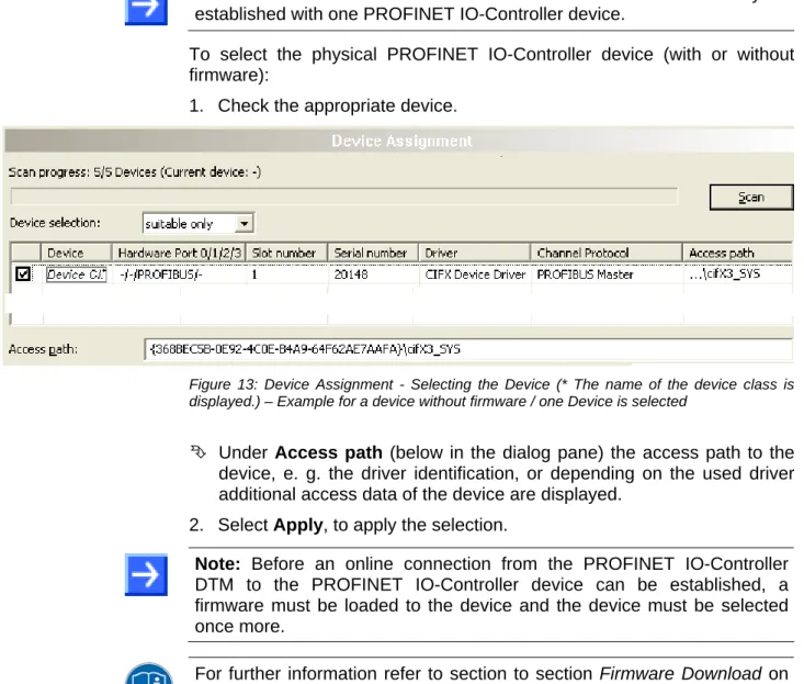
PROFINET IO-Controller device and select it.
If the device did not get a firmware or shall get a new firmware:
1. first you scan for the device (with or without firmware) and select the
device,
2. then you download a firmware to the device and
3. subsequently you scan for the device (with firmware) once more and
select the device again.
3.4.1
Scanning for Devices
1. Select
Settings > Device Assignment
in the navigation area.
The dialog pane
Device Assignment
is displayed.
Figure 11: Device Assignment - detected Devices (* The name of the device class is displayed.) – Example for a device without firmware
2. Under
Device Selection
select
suitable only
.
3. Select
Scan
, to start the scanning process.
In the table all devices are displayed, which can be connected to the
PROFINET IO-Controller DTM via the preselected driver.
Parameter Meaning Range of Value / Default Value
Device selection Selecting suitable only or all devices. suitable only, all Device Device class of the PROFINET IO-Controller Devices.
Hardware Port 0/1/2/3
Shows, which hardware is assigned to which communication interface. Slot number Shows the Slot Number (Card ID) preset at the PC card cifX via the Rotary
Switch Slot Number (Card ID).
The indication n/a means that no Slot-Nummer (Card ID) exists. This will occur if the PC card cifX is not equipped with a Rotary Switch Slot Number (Card ID) or for PC cards cifX equipped with a Rotary Switch Slot Number (Card ID) if the rotary switch is set to the value 0 (zero).
1 to 9, n/a
Serial number Serial number of the device Driver Name of the driver
Channel Protocol Shows, which firmware is loaded to which device channel.
The data for the used channel consists of the protocol class and the communication class.
a.) For devices without firmware: Undefined Undefined,
b.) For devices with firmware: Protocol name corresponding to the used Firmware
Access path (last column on the right)
Depending on the used driver in the column Access path different data to the device are displayed.
For the cifX Device Driver the following data are displayed: a.) For devices without firmware: …\cifX[0toN]_SYS, b.) For devices with firmware: …\cifX[0toN]_Ch[0to3]. cifX[0toN] = Board number 0 to N
Ch[0to3] = Channel number 0 to 3
Depending on the device and on the driver:
board or channel number, IP address or COM interface
Access path (at the lower side of the dialog pane)
If in the table a device is checked, under Access path (at the lower side of the dialog pane) the driver identification or depending on the used driver additional data to the device will be displayed.
For the cifX Device Driver the following data are displayed: a.) For devices without firmware: …\cifX[0toN]_SYS, b.) For devices with firmware: …\cifX[0toN]_Ch[0to3]. cifX[0toN] = Board number 0 to N
Ch[0to3] = Channel number 0 to 3
driver identification (ID)
depending on the device and on the driver:
board or channel number, IP address or COM interface Table 13: Parameters of the Device Assignment
3.4.1.1
Scanning for all Devices or for suitable only
all
1. Under
Device Selection
select
all
.
2. Select
Scan
.
Figure 12: Device Assignment - detected Devices (* The name of the device class is displayed.) Example for Devices without Firmware