SOA-based Integration of the Internet of Things in Enterprise Services
Patrik Spiess
1, Stamatis Karnouskos
1, Dominique Guinard
1,2, Domnic Savio
1,
Oliver Baecker
1,3, Luciana Moreira S´a de Souza
1, and Vlad Trifa
1,2 1SAP Research,
2ETH Zurich,
3University of St. Gallen
Email: [email protected]
Abstract
Advances in the areas of embedded systems, computing, and networking are leading to an infrastructure composed of millions of heterogeneous devices. These devices will not simply convey information but process it in transit, connect peer to peer, and form advanced collaborations. This “In-ternet of Things” infrastructure will be strongly integrated with the environment, and its integration with the enterprise systems will not only further blur the line between business IT systems and the real world, but will change the way we design, deploy, and use services. New opportunities can emerge for businesses, which can now closely collaborate with the real world. The work presented here proposes an architecture for an effective integration of the Internet of Things in enterprise services.
1
Motivation and Vision
Traditionally, the systems of an enterprise controlling physical processes (like manufacturing, logistics execution, energy monitoring, building automation, etc.) use differ-ent standards for data and communication than its business software systems. We see a paradigm change as the for-mer breed of systems increasingly adopt the standards of the latter. It is expected that this trend will continue, while in parallel the number of connected devices will explode.
As we are moving towards the ”Internet of Things” as depicted by [3], millions of devices will be interconnected, providing and consuming information available on the net-work and cooperate. As these devices need to interoperate, the service-oriented approach seems to be a promising so-lution, i.e. each device should offer its functionality as stan-dard services, while in parallel it is possible to discover and invoke new functionality from other services on-demand.
As depicted in Figure 1, future infrastructures will be service-oriented. As such, new functionality will be intro-duced by combining services in a cross-layer form, i.e.
ser-Service Mid dleware Service Service Service Service ? Service Business Process supported by a cross-layer service
Service Service Direct access to web service enabled
devices Indirect access to
(web service enabled) devices via middleware
ERP
WS(A)N (non-WS)Legacy Service
Mediator Gateway Service
Dynamic Discovery of Devices / Services & P2P Communication
Service
Figure 1. Vision of Web Service Mash-Ups
vices relying on the enterprise system, on the network it-self and at device level will be combined. New integration scenarios can be applied by orchestrating the services in scenario-specific ways. In addition, sophisticated services can be created at any layer (even at device layer) taking into account and based only on the provided functionality of other entities that can be provided as a service [5]. In parallel, dynamic discovery [2] and peer-to-peer communi-cation will allow to optimally exploit the functionality of a given device. It is clear that we move away from isolated stand-alone hardware and software solutions towards more cooperative models.
The convergence of solutions and products towards the SOA paradigm adopted for smart embedded devices con-tributes to the improvement of the reactivity and perfor-mance of industrial processes, such as manufacturing, logis-tics, and others. This will lead to information being avail-able in near real-time based on asynchronous events, and to business-level applications that are able to use high-level information for various purposes, such as diagnostics, per-formance indicators, traceability, etc. SOA-based vertical
integration will also help to reduce the cost and effort quired to realize a given business scenario as it will not re-quire any device drivers or third-party solutions.
2
SOCRADES Integration Architecture
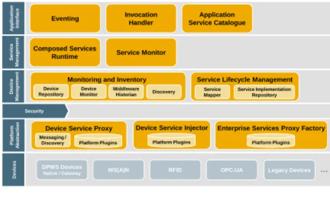
To realize an effective integration of the capabilities of-fered by the Internet of Things, we have designed an archi-tecture (depicted in Figure 2) that exposes real-world de-vices with embedded software to standard IT systems by making them accessible in a service-oriented way. The re-quirements we want to cover as well as the functionality to be realized is analyzed in [6],[1]. The architecture im-plemented hides the heterogeneity of hardware, software, data formats and communication protocols that is present in today’s embedded systems. The specifications foster open and standardized communication via web services at all lay-ers. The following layers can be distinguished: Application Interface, Service Management, Device Management, Se-curity, Platform Abstraction and Devices.
Application Interface: The SOCRADES Integration
Architecture (SIA) enables enterprise-level applications to interact with and consume data from a wide range of net-worked devices using a high-level, abstract interface that features web services standards. Those standards already constitute the standard communication method used by the components of enterprise-level applications. Web services are the technology canonically used to implement business processes, which are frequently modeled as orchestrations of available web services. This allows networked devices that are connected via the middleware presented here to di-rectly participate in business processes while neither requir-ing the process modeler nor the process execution engine to know about the details of the underlying hardware.
The integration architecture features a messaging sys-tem, because the application should be able to consume any events whenever it is ready to and not when a low-level ser-vice happens to send them. It also allows the application to interact with devices that are only intermittently connected, receiving notifications when a certain device becomes avail-able again or have the system cache the message and deliver it when the device is ready to receive it. Finally there is a service catalog that users and applications can query. It finds and delivers service descriptions and pointers to run-ning service instances. Both atomic services hosted by the devices and higher-level composed services are listed here.
Service Management: All functionality offered by
net-worked devices is abstracted by services. Either devices offer services directly or their functionality is wrapped into a service representation. On this layer of the integration architecture and on all layers above, the notion of devices is abstracted from and the only visible assets are services. An important insight into the service landscape is to have a
SOCRADES Integration Architecture
A pplic a tion In terf ace Eventing Invocation Handler Application Service Catalogue Servi ce Man ag emen t Composed Services
Runtime Service Monitor
Devi ce Man ag emen t Platform A b stract io n Devi ces
Monitoring and Inventory Service Lifecycle Management Device Repository Device Monitor Middleware Historian Discovery Service Mapper Service Implementation Repository
Enterprise Services Proxy Factory Platform Plugins Device Service Injector
Platform Plugins Device Service Proxy
Platform Plugins Messaging /
Discovery
DPWS Devices
Native / Gateway WS(A)N RFID OPC-UA Legacy Devices …
Security
© SAP 2008 / Page 2
Figure 2. SOCRADES Integration Architec-ture
repository of all currently connected service instances. This layer also provides a runtime for the execution of composed services. We support the composition of business processes primarily by offering an execution service for underspec-ified BPEL processes, meaning that service compositions can be modeled as business processes where the involved partners do not need to be explicitly specified at design time. This flexibility is needed since the set of services offered at the device level is dynamic; as (potentially mobile) devices connect and disconnect or are re-configured, the available service set changes frequently. Traditional business process execution languages like BPEL are not built to support such dynamics. With some proposed extensions to BPEL and the execution support for the extended processes, the process modeler has unprecedented flexibility.
Device Management: All devices are dynamically
dis-covered, monitored and their status is available to the en-terprise services. Furthermore, it is possible to remotely deploy new services during run-time, in order to satisfy ap-plication needs.
Security: Both devices and back-end services may only
be accessed by clients that have a certain role and provide correct credentials that authenticate themselves. This layer implements the correct handling of security towards the de-vices and the enterprise-level applications.
Platform Abstraction: As stated before, devices either
offer services directly or their functionality is wrapped into a service representation. This wrapping is actually carried out on the platform abstraction layer. In the best case, a device offers discoverable web services on an IP net-work. In this case no wrapping is needed because services are available already. If the device type however does not have the notion of a service (it might use a message-based or data-centric communication mechanism), the abstraction into services that offer operations and emit events can be a complex task. In addition to service-enabling the communi-cation with devices, this layer also provides a unified view on remotely installing or updating the software that runs on
Figure 3. Eventing
devices and enables the devices to communicate natively, i.e. in their own protocol with back-end devices.
Devices: Heterogeneous Devices are expected to
con-nect to the architecture. These include industrial devices, home devices, or IT systems such as mobile phones, PDAs, production machines, robots, building automation systems, cars, sensors and actuators, RFID readers, barcode scan-ners, or power meters. We used several of the listed types of devices during prototype implementations as shown in the Demonstration section.
3
Architecture Design
The architecture components presented in the following subsections have all have been implemented based on open WS-* standards in Java EE 5 on SAP NetWeaver platform, using EJB 3.0 and JPA.
3.1
Eventing
This component is an implementation of the WS-Brokered Notificationstandard, implementing publish and subscribe functionality, to distribute information about events of interest. Both Push or Pull type delivery are sup-ported and both involve the role of ”Consumer” and ”Pro-ducer”. Figure 3 shows a high-level view on the Eventing component.
The Eventing component acts as an intermediary be-tween a Producer and the entity that has interest in the gen-erated events. For example, a shop floor device could prop-agate sensor data through the Eventing component acting as a Producer.
The WS-Notification standard consists of 3 specifica-tions: WS-Notification, WS-Brokered Notification,and WS-Topic.
WS-Notification defines consumer and producer roles and the interfaces both have to provide. This allows for a point to point event subscription and delivery. The pro-ducer needs to provide the notification interface where the producer sends the notifications to and the producer has to provide the subscription interface so that the consumer can subscribe.
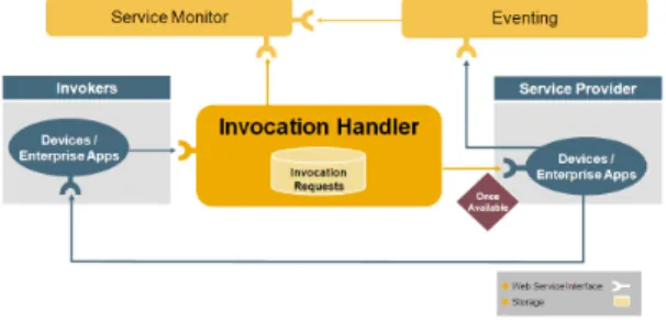
Figure 4. Invocation Handler
WS-Brokered Notification builds on top of WS-Notification and specifies an intermediary called notifica-tion broker, which is exactly what we have implemented in the Eventing component. It provides the subscription in-terface on behalf of the producer and the notification inter-face on behalf of the consumer. This drastically reduces the complexity of consumers and producers and allows flexi-ble relationships, that can involve producers/consumers un-known at design and deployment time. Additionally, the broker offerspull pointfunctionality, i.e. it can collect no-tification for a consumer until it retrieves them, further re-ducing the complexity of the consumer.
WS-Topics defines hierarchical topic trees that can be specified and used to declare event types when producing and event filters when subscribing to events. The event-ing component implements basic topic expressions, the sim-plest form of topics specified.
3.2
Invocation Handler
The Invocation Handler (Figure 4) implements function-ality to act as an intermediary for service invocations. It is capable of buffering an invocation in case an endpoint is not available. Furthermore, it supports two different types of delivery (Direct Service Response and Push) and provides interfaces for the invoker to query for an invocation request status and canceling a pending invocation.
When using the Direct Service Response delivery, the invoker has to supply an endpoint which supports retriev-ing the service invocation response directly. This endpoint can be the invoker itself or any other supporting entity. The Invocation Handler passes the given endpoint as the return endpoint when invoking the service. The delivery mecha-nism Direct Service Response is depicted in Figure 4.
When using the Push delivery, the Invocation Handler receives the service invocation response and publishes it to the Eventing component. The invoker has to supply the description of the event that should be used when the re-sponse is propagated to the Eventing component. Using the Push delivery implies that the invoker has previously regis-tered interest for the supplied event description, using one
Figure 5. Application Service Catalogue
of the Eventing subscription types (Push/Pull). Therefore the Eventing component is used as an intermediary for de-livery of the service invocation response.
The component implements functionality to retrieve the current status of a request for invocation. This is one of ”Pending” and ”Not Pending”. ”Pending” implies that the service invocation was not processed, possibly because the service was not yet available. ”Not Pending” implies that the service invocation was executed, if the given request for invocation was registered previously. This functionality is used by the invoker to know whether a service invoca-tion happened within a given time or whether there was a conflict that prevented the service to be executed properly. The component implements functionality to remove a re-quest for invocation. The invoker can decide to remove a request in case a response or the invocation of the service would result in unwanted consequences or be of no interest.
3.3
Application Service Catalogue
One of our main targets and justification for wanting WS everywhere is the fact that they enable more flexibil-ity. Once every service is exposed using the same interfaces one can really think about combining the services and creat-ing new behaviors for the application. Yet, composition and service consumption does not really make sense if services cannot be searched for. This is the goal of the Application Service Catalogue. Figure 5 depicts its subcomponents. It is the search engine of the architecture that enables the ap-plications to look for services based on queries.
The catalogue is composed of three subcomponents:
QueryEngine: The QueryEngine is the core of the search;
it consumes a simple text query and returns an ordered list of matching Service Types. In order to go beyond the sim-ple query matching of a service name or description it first uses a concrete instance of a pluggable component called QueryStrategy with the goal to define how the simple query should be extended before processing. The use of a Query-Strategy component prevents from locking the architecture
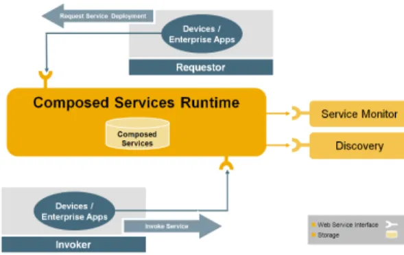
Figure 6. Composed Services Runtime (CSR)
with a search method that is not appropriate.
BestEffortComponent: This is responsible for selecting
the best possible device running the selected service. ”Best” is here meant in terms of QoS (Quality of Service). It takes into account the information held by the Device Monitor namely, status, battery life, etc.
OnDemandDiscoveryAndDeployment: This
compo-nent is responsible for initializing the dynamic search for services. When a service type corresponding to the query is found but the Best Effort component does not find a running instance, the On Demand Discovery and Deployment com-ponent will try: (i) to force a discovery for such a service, using the Discovery component, and (ii) to inject the ser-vice on a deser-vice, using the Serser-vice Mapper and the Deser-vice Service Injector.
3.4
Composed Services Runtime
Composed services are described in BPEL, which com-municates with service partners over partner links. At de-sign time, all partner links must be bound to concrete ser-vice types. Only the actual endpoints can be unknown at design time. CSR can host several composed services, de-pending on the device capacity, e.g. RAM or CPU power. Moreover, as we need a JVM to run CSR, the performance of CSR also depends on the garbage collector and the Java heap size of that JVM. CSR (depicted in Figure 6) basi-cally provides two interfaces for web service consumers: the interface for deploying/undeploying composed services and the interface for using composed services. For deploy-ing new composed services, CSR hosts a service called De-ployment Service. Deploying a composed service on CSR means that a SOAP message is sent to the Deployment Ser-vice, containing the URL location of the BPEL description of the new composed service and also the URL location of the deployment descriptor of that service. A new composed service instance is created, hosted on CSR, and represented in the Service Monitor. During the execution of a composed service runtime, CSR asks the Service Monitor for the cost
Figure 7. Service Monitor
information of each sub-service invocation, in order to cal-culate the total cost of the whole composed service execu-tion. CSR stores this total cost into the Service Monitor, indicating the performance of the composed service. CSR has also the functionality to log the response time of each individual sub-service invocation and size of the SOAP re-quest/response. From this information, CSR can update the cost information of each individual service instance in the Service Monitor.
3.5
Service Monitor
The service monitor (depicted in Figure 7 is storing fast-changing, live and up-to-date data about the currently us-able service instances. The storage is realized as a in-memory data structure rather than a database structure for fast access and to allow performing easy updates. Examples of usage include: a service detects that it is malfunctioning and self-reports that fact to the service monitor which gen-erates an alert. Similarly when a device joins the network, the Service Monitor picks up the events from the Discovery component and stores the fact that the services are there.
3.6
Monitoring and Inventory
The Monitoring and Inventory is composed of several components: Device Repository, Device Monitor, Middle-ware Historian, and Discovery.
The Device Repository component is responsible for
storing static information about the devices available in the system. To facilitate the registration of numerous devices that have common characteristics, the Device Repository supports the concept of Device Type. The Device Type contains Properties and Features which describes common characteristics of a class of devices. For example, a wireless sensor node such as a SunSPOT (www.sunspotworld. com)can be registered as a Device Type with tempera-ture and acceleration sensors as featempera-tures. Numerous sen-sor nodes can be registered using the same device type as reference.
Figure 8. Monitoring and Inventory
Figure 9. Device Discovery
The Device Monitor monitors devices and detects
events like failures. When a malfunction is detected, the component triggers a Fault Event which is propagated to interested parties. As each device has different character-istics and behavior, a set of fault detection techniques is required to monitor devices. These techniques can make use of events generated by the devices, for instance to iden-tify if unexpected value readings were generated. Another possibility is to invoke specific methods on the devices, for instance to ping the device in order to verify if it is still ac-tive. New techniques can be used by implementing another monitoring method.
TheMiddleware Historianacts as an event archive for
the architecture. Data from the devices (due to events or in-vocation), middleware system information, debugging mes-sages, etc. can be stored there and are accessible for corre-lation of events.
TheDiscoverycomponent is able to find devices present
on a network, and retrieve information about them and their hosted services to be used by other components from the ar-chitecture. Two distinct functional modes are implemented by the discovery unit. The first is referred to as ”passive discovery”, whose role is to listen to the network for an-nouncements from new, unknown devices that connect to the network, dynamically retrieve their metadata and use the eventing mechanism to notify the systems about the devices and their hosted services. The second mode, called ”active discovery”, is responsible for dynamic search of specific de-vices or serde-vices, and particularly suited for contexts where
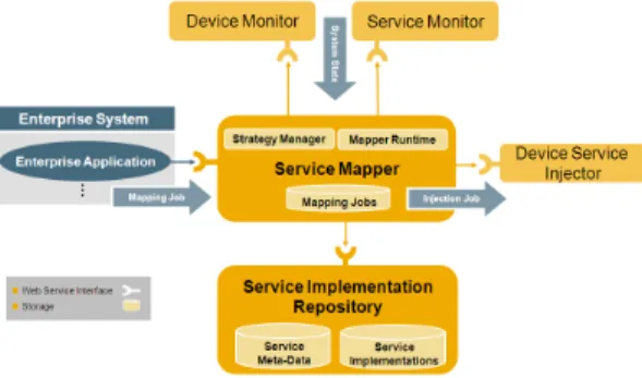
Figure 10. Service Lifecycle Management
new devices with unknown capabilities continuously con-nect to the system.
3.7
Service Lifecycle Manager
The service lifecycle management [4] (depicted in Fig-ure 10) component consists of two main sub-components: the Service Mapper and the Service Implementation Repos-itory. The Service Mapper (SM) performs deployment planning and deployment execution within the SOCRADES middleware. Whenever a business process is created it de-cides how this process can be represented by the middle-ware respectively by the services hosted on devices within the device layer of the middleware. The SM therefore gen-erates desired service mappings that describe which ser-vices on which deser-vices may be used during execution of a business process (while the actual decision about the used service instance is made by the Service Monitor at run-time). Desired mappings are then transformed into deploy-ment lists, which describe actions to be performed in order to establish a desired mapping. Actions included in a de-ployment list may be (un)dede-ployment, (de)activation, mi-gration, or configuration of services. The decisions of the SM therefore tremendously influence the reliability of the SOCRADES middleware and thus the reliability of all busi-ness processes based on it.
The Service Implementation Repository (SIR) saves all services which are available for composition of new ser-vices, orchestration of business process or deployment within the SOCRADES middleware. Saving a service means saving its metadata as wells as associated arbitrary content like service implementations. The SIR is therefore a registry repository rather than only a repository as indi-cated by its name. The SIR generally offers two kinds of operations related to services which together make up the service lifecycle management of the SIA: management and query. Management refers to the publication of new ser-vices, updating existing services (incl. versioning), creation of configurations and deprecation of services. Querying a service may be done using different query languages and
Figure 11. Device Service Injector
constructs and may search for service metadata or associ-ated implementations. All operations may be approved be-fore execution according to rules and guidelines thus en-forcing a governance process.
3.8
Device Service Proxy
The device service proxy eases the integration of several categories of heterogeneous devices. Plugins can be writ-ten that uniformly address devices based on their capabili-ties. As an example, we have implemented a Devices Pro-file for Web Services (DPWS) plug-in that can dynamically discover and integrate any DPWS device (such as the ones described in the Demonstration section). Similarly other de-vices based on OPC-UA, specific RFID or legacy protocols can be integrated provided that a platform plug-in is written for their category.
3.9
Device Service Injector
The Device Service Injector (DSI) is responsible for the execution of deployment levels and steps during the pro-cessing of a deployment list by the Service Mapper. The DSI utilizes various injectors. For each deployment plat-form supported by the SOCRADES middleware one injec-tor implementation exists of which various instances dur-ing runtime may be started. Each instance registers itself during start up with the DSI and may thus be used for the deployment execution. Injector implementations may ei-ther run locally as a subcomponent of the DSI or as remote components possibly on different subnets/locations. This allows the DSI to always choose the most suitable injec-tor currently available for each specific deployment step. Incoming deployment steps are saved within a command queue and are executed either sequentially or in parallel. Delivery of execution results to the Service Mapper may be performed asynchronously. In case errors occur during ex-ecution of deployment steps, all steps of the same job are
Figure 12. Enterprise Services Proxy Factory
either canceled if they are still in the command queue or compensated if they were already executed.
3.10
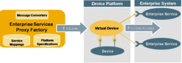
Enterprise Services Proxy Factory
The Enterprise Services Proxy Factory provides faces for the creation of virtual devices that act as inter-mediaries between the device level and enterprise services. Such proxies might contain a definable set of adapters for enterprise services and provide their respective device in-terfaces on a target platform. The component defines a set of requirements that need to be fulfilled in order to deploy such virtual devices on a target platform. This includes the installation of platform support on the one hand and one the other hand the formal description of a mapping between device level and enterprise service messages. The Enter-prise Services Proxy Factory includes subcomponents that facilitate the process of mapping a device level invocation message to a target enterprise service request and support a customizable set of rules that are applied when converting messages.
4
Demonstration
To demonstrate that the aforementioned ideas can be re-alized, we have used state of the art technologies to im-plement prototypes. Several prototypes have been imple-mented as proof of concept.
The systems described have common characteristics where we focus on smart devices like sensors, PLCs or IT devices that offer web service interfaces, either di-rectly or through the use of gateways or service mediators. Through these interfaces they offer functional services (e.g. start/stop, swap to manual/automatic mode) or status infor-mation (e.g. power consumption, mode of operation, usage statistics). In our prototypes, the business logic services are supported by a service composition engine and visualized using a visualization toolkit. An operator can use existing tools like SAP Manufacturing Integration and Intelligence (SAP MII) to create the business rules. The SIA enables sophisticated business software such as ERP or PLM sys-tems to interact with the real world. By making web service mash-ups of services running on the enterprise, middleware,
Figure 13. Heterogeneous Web-Service en-abled Devices in an Event-based Infrastruc-ture
and device layer, we can provide users with a rich visualiza-tion of the real-world status.
The integration of heterogeneous devices is clearly de-picted in our latest prototype that successfully shows how several devices supporting web services (or being wrapped by them) can be integrated via the proposed architecture. We have taken several IP devices and wrapped their func-tionality with web services. More specifically as depicted in Figure 13 we used the following devices: An RFID
reader: Appearing RFID tags are read by the reader which
raises events showing info with respect to the tag. Each tag is considered to be integrated with a product and serves as a token that links it with business information (e.g. order de-tails). A robotic arm: The functionality (grab, move, etc.) of the robotic arm controller has been wrapped. An
elec-tricity IP switch: An alarm lamp has been attached in an
electricity IP switch, which offers the on/off functionality as a web service. Wireless sensors: One sensor controls the emergency button. The emergency button has been attached to the IO pins of the SunSPOT wireless sensor. Pressing or releasing the button is captured by the SunSPOT, and an WS-event is generated. Another wireless sensor is used for vibration monitoring. The capability of SunSPOTs to mea-sure acceleration is used for vibration monitoring via the sensor mounted on the robotic arm. This sensor monitors the transportation conditions of the product to make sure it adheres to the product-specific quality guidelines.
Composing application scenarios is dynamically done by orchestrating the available services. The dynamicity also comes from the fact that the SIA is an event-based infras-tructure. A typical scenario is the following: As production parts arrive at the factory shop floor they are equipped with an RFID tag. As they reach the processing point, the tag is read by the RFID reader. An event is generated by the reader with all the necessary data like the RFID number and stored on the network. The robot gets notified by this event
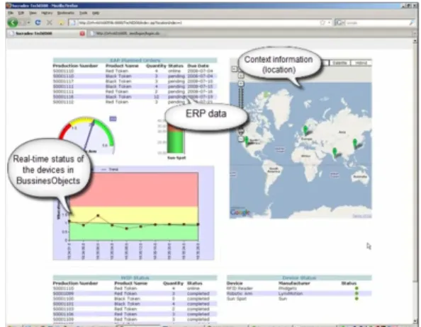
Figure 14. Real time reporting via Enterprise reporting tools
(as it has subscribed to the service) and picks up the pro-duction part. By matching data from the enterprise system and the RFID tag, it knows how to further process the part. In parallel the SunSPOT sensor mounted on the robot mon-itors the vibration and if it exceeds a specific threshold an event is raised to immediately stop the process (quality con-trol). The same holds true for the emergency switch, if an operator at the shop floor for any reason wants to immedi-ately stop the process (e.g. due to an accident) s/he presses this switch, which is controlled by a SunSPOT that again generates an event.
Once such an emergency event is propagated, devices that consume it react accordingly. The robot receives the emergency shutdown event and immediately stops its op-eration. Also the IP electricity switch, once it receives the event, turns on the emergency light. At business layer, there is an enterprise application such as shop-floor reporting re-alized by the SAP product Business Objects. There, we have a real-time monitoring of the shop-floor status as the application also subscribes to all events raised. The plant manager can immediately see the status of the ERP orders (Figure 14), the production progress, the device status, as well as a global view on all factories and the possible side-effects of a production line delay due to shop-floor device malfunctions.
All of the communication is done via web service tech-nologies and the realization of this specific scenario became possible by having a composition of the available function-ality that all devices and applications expose as a service. In legacy systems, integration of a new device or reassignment of its role would result in reconsidering how the device inte-grates with other devices and how they control it. However with the SOA approach described, the implementation of a new scenario is possible by modifying the orchestration of the services already available.
An online demo of the Integration Architecture is avail-able at http://socrades.dyndns.org:50000/SIA_
demo_web/demo-intro.html.
5
Conclusion and Future Work
We have presented the design of an architecture that can strongly couple the envisioned Internet of Things infrastructure with enterprise services. The majority of the specified functional-ity has been implemented and trialed.
The approach is event-based and its interaction with external entities as well as internal communication is based on web ser-vices. Theoretically each component could be hosted in different locations. As an example, parts of the architecture could be run-ning in the cloud offering high-performance services, while parts interacting locally with the devices could run even on embedded systems located at the device layer.
The design and implementation was done with scalability in mind. However, we plan to conduct extended scalability and per-formance tests in the future. A special focus will be on perfor-mance tests when running DPWS on resource-constrained devices. Future work will also include the extension of the architecture to support additional devices using OPC-UA and REST plug-ins. Validation trials with real-world devices are planned in the au-tomation and energy domain.
Acknowledgments
The authors would like to thank the European Commission and the partners of the European IST FP6 project Service-Oriented Cross-layer infRAstructure for Distributed smart Embedded de-vicesSOCRADES (www.socrades.eu), for their support.
References
[1] L. M. S. de Souza, P. Spiess, D. Guinard, M. Koehler, S. Karnouskos, and D. Savio. Socrades: A web service based shop floor integration infrastructure. InProc. of the Internet of Things (IOT 2008). Springer, 2008.
[2] W. K. Edwards. Discovery systems in ubiquitous computing. IEEE Pervasive Computing, 5(2):7077, 2006.
[3] E. Fleisch and F. Mattern. Das Internet der Dinge. Springer, 1 edition, July 2005.
[4] T. Frenken, P. Spiess, and J. Anke. A Flexible and Extensible Architecture for Device-Level Service Deployment, volume 5377 ofLNCS, pages 230–241. Springer, December 2008. [5] F. Jammes and H. Smit. Service-oriented paradigms in
indus-trial automation. IEEE Transactions on Industrial Informat-ics, 1(1):62–70, Feb. 2005.
[6] S. Karnouskos, O. Baecker, L. M. S. de Souza, and P. Spiess. Integration of soa-ready networked embedded devices in en-terprise systems via a cross-layered web service infrastruc-ture. InProc. of the 12th International Conference on Emerg-ing Technologies & Factory Automation (ETFA), pages 293– 300, 25–28 Sept. 2007.