MITEL BORDER GATEWAY Release 8.0
ENGINEERING GUIDELINES
The information contained in this document is believed to be accurate in all respects but is not warranted by Mitel Networks™ Corporation (MITEL®). The information is subject to change without notice and should not be construed in any way as a commitment by Mitel or any of its affiliates or subsidiaries. Mitel and its affiliates and subsidiaries assume no responsibility for any errors or omissions in this document. Revisions of this document or new editions of it may be issued to incorporate such changes.
No part of this document can be reproduced or transmitted in any form or by any means - electronic or mechanical - for any purpose without written permission from Mitel Networks Corporation.
Trademarks
Mitel is a trademark of Mitel Networks Corporation.
Other product names mentioned in this document may be trademarks of their respective companies and are hereby acknowledged.
MBG - Engineering Guidelines DK121047
Release 8.0 June 7, 2013
®,™ Trademark of Mitel Networks Corporation © Copyright 2011, Mitel Networks Corporation
C
ONTENTS
About this Document... 1
Overview ... 1
Prerequisites ... 1
About the MBG Documentation Set ... 1
Supported Configurations... 2
Services... 2
Teleworkers and Remote Offices... 2
Overview...2
Mitel Border Gateway as Internet Gateway...3
Additional Local Networks...4
Mitel Border Gateway in a DMZ...5
NAT Traversal for MICD... 6
Secure Gateway for Broadview Networks silhouette HKS...6
Secure Recording Environment... 7
MBG Deployed on the LAN for Call Recording...7
SIP Trunking... 10
Daisy-Chain Deployments... 11
Special IT Policy Deployment...11
Reduced Bandwidth for Remote Sites...12
MBG in MAS... 13
MAS on the LAN...13
MAS on the Network Edge...13
MBG in vUCC... 14
Partial Service Configurations ... 14
Common Requirements... 15
Supported ICP Versions... 15
Administrative Access... 15 Firewalls (DMZ deployment)... 15 Known Issues...16 Checkpoint “NG” Firewalls...16 Port-Forwarding Firewalls...16 SIP-Aware Firewalls...16
UDP Flood Protection...16
Firewall Configuration Common to all Services...17
Remote Phone Access... 18
Remote Site Requirements... 18
Router...18
VPN Connectivity...19
Using an Existing VPN...19
Corporate Firewall & Network Configuration for VPN Access...19
Bandwidth Requirements for the Remote Site...19
Configuring the Remote Site Firewall...21
TFTP Behavior... 22
Firewall Configuration for Remote MiNet Devices...22
Configuring MBG for Remote SIP Devices... 23
Remote SIP Device Limitations...23
Tuning Global Parameters...23
DNS Support...23
Firewall Configuration for Remote SIP Devices...23
SIP Trunking... 25
Overview... 25
Bandwidth Requirements... 25
Call Recording... 27
Call recording vs. Local streaming... 27
Indirect Call Recording... 27
Additional Application Requirements... 28
Unified Communicator Advanced (UCA) v4.0+...28
Mitel Contact Center... 28
Web Proxy... 29
Special consideration for MCA through Web Proxy...29
Remote Management Service... 29
Additional Security Considerations... 30
SIP Security... 30 Traffic Shaping... 31 Overview... 31 Technical Details... 31 Clustering... 33 Overview... 33 Cluster Zones... 33 Node Weighting... 34 Additional Considerations... 35
Firewall Configuration for Clustering... 35
Advanced Options... 36
Resiliency... 36
IP Translations... 36
Streaming Addresses... 37
DMZ Deployment Profile...37
Gateway Deployment Profile...37
RTP Frame Size... 37
TFTP Block Size... 38
Set-side Codec... 38
SRTP Port Range... 38
DSCP... 38
Sizing Your Installation... 40
Determining Line Size for Large Sites...40
Step One: Determine Call Rate...40
Step Two: Determine Service Rate...40
Step Three: Determine Grade of Service...40
Step Four: Erlang-B Calculator...41
Determine Call Equivalents... 41
Determine Bandwidth Requirements... 41
G.711 Calculation...42
G.729a Calculation...42
Video Calculation...43
Fax Calculation...44
Call Recording Calculation...44
Example Bandwidth Calculation...44
Hardware Selection... 45
Performance Characteristics and Limits...45
Physical Hardware...45
VMWare Virtual Hardware...46
Web Proxy and Remote Management Service Requirements...46
UCA and MCA Requirements... 46
Mitel Contact Center Softphone Requirements...47
Host Server Requirements... 49
Hardware...49
Software...50
High-Availability... 50
Solutions To Common Problems... 51
Changing a Cluster Node's IP Address...51
T.38 Faxing Does Not Work With NAT... 51
1 About this Document
1.1 Overview
The purpose of this document is to describe configuration rules, provisioning, and performance information for the Mitel Border Gateway, and associated products in order to assist in sales and support of this product. This information is intended for Training, Sales and Product support staff and complements other sales material and product documentation.
Note: The Secure Recording Connector (SRC) has been consolidated into MBG. Accordingly, although this document discusses the SRC control interface and its protocol, it does not treat the SRC as a separate feature.
1.2 Prerequisites
The Mitel Border Gateway application runs on the Mitel Standard Linux (MSL) Server. The reader should first become familiar with the MSL Installation and Administration Guide and the MSL Qualified Hardware document. These are available from http://edocs.mitel.com.
1.3 About the MBG Documentation Set
Mitel documentation is available from http://edocs.mitel.com. (Note: a Mitel On-Line account is required to access eDocs.) The following guides provide complete information about MBG:
• The MBG Engineering Guidelines (this document).
• The Mitel Border Gateway Blade Installation and Maintenance Guide provides information about system requirements, installation of MBG, and configuration of MBG options and firewalls.
• The Mitel Border Gateway Online Help provides information about MBG configuration and maintenance. • The Remote IP Phones Configuration Guide provides information about configuring remote phones.
2 Supported Configurations
2.1 Services
MBG provides the following services:
• Remote MiNet IP Phones The classic use of MBG, formerly known as the Teleworker Solution, permits remote MiNet phones to securely access the corporate phone network over the Internet.
• Remote SIP IP Phones Permits Teleworker functionality for SIP hard or soft phones over the Internet. • SIP Trunking Allows a corporate phone switch to connect SIP trunks to a SIP trunk provider, protecting
the switch from malformed messages, unauthorized use, and various attacks, and providing an anchor point for media streams.
• Call Recording Formerly the Secure Recording Connector, this service allows secure recording of phone calls by a third-party application
In addition, the MBG server can host the Remote Proxy Services blade to provide the following services: • Web Proxy: end-user access from the WAN to applications hosted inside the firewall
• Remote Management Service: administrative access from the WAN to applications hosted inside the firewall
Please refer to the Remote Proxy Services documentation for details.
MBG can be deployed in several ways depending on the services required.
2.2 Teleworkers and Remote Offices
Overview
The original design intent of MBG is to provide a Teleworker solution. Once an MBG server is installed,
extensions from the office PBX can be extended across the Internet to permit MiNet phones to work from homes, remote offices, hotels, etc.
In this use-case, either the server-gateway profile or DMZ profile could be used depending where on the network MBG is to be deployed. If deploying behind an existing firewall on a DMZ, then a single network interface and DMZ profile is appropriate. If deploying beside an existing firewall, or if there is no existing firewall, then server-gateway profile is appropriate.
Failure to follow these guidelines will result in one-way or no-way audio.
Warning: Some firewalls which use port-forwarding to simulate a DMZ are Port-forwarding Firewalls. See the Common Requirements chapter for full details.
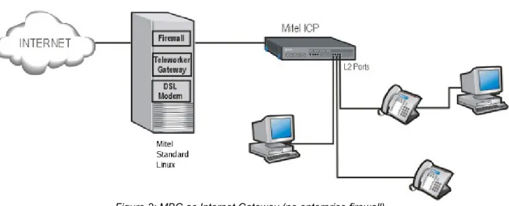
Mitel Border Gateway as Internet Gateway
Mitel recommends deploying the Mitel Standard Linux server with Mitel Border Gateway as the Internet gateway and firewall for any enterprise without an existing firewall. Figure 2 shows a example of this configuration using the Mitel Border Gateway and a Mitel Communications Director (3300 ICP).
MBG requires two network interfaces and two addresses for this configuration. The external address must: 1. Be a static address that does not change
2. Be directly attached to a NIC on the MSL server 3. Be reachable from the public network/Internet 4. Be reachable from the internal network/LAN 5. Not be subject to NAT or behind another firewall
The interface may be configured via DHCP, PPPoA, PPPoE or similar technology, but the address it receives must always be the same.
Warning: If the external address changes, all teleworker phones must be reprogrammed with the new address.
An enterprise can take advantage of the DSL, authenticated DHCP and PPPoE/PPPoA1 capabilities of the MSL
server. MSL additionally provides NAT for all devices at the enterprise, a stateful packet filter firewall, and optional port-forwarding.
Note: If desired and if hardware is available, a third interface may be configured in MSL. This interface might be useful as a dedicated interface for clustering if a network between the MBG servers can be set aside for this purpose.
Alternatively, the third interface could be put into bridged mode on MSL 9.2+ to permit an MBG server in parallel with an existing firewall to transparently handle all traffic from that firewall and accomplish traffic shaping. See
Traffic Shapingfor full details.
Additional Local Networks
Additional internal networks or subnets that require access to the Mitel Border Gateway can be added via the
Local Networks panel of the server manager. This access can be limited to individual hosts, or large network blocks can be used. In all cases, the Router property should be set to the address of the router on the subnet attached to the MSL server's internal interface.
For example, to allow access from the single subnet 192.168.12.0/24, you would enter a network of
192.168.12.0 and a mask of 255.255.255.0 in the Local Networks panel, plus the address of the router on the local subnet through which this network can be reached.
If the customer’s network has multiple subnets with a common prefix, access can be allowed from the prefix. For example, if the customer uses various subnets within the 192.168.0.0/16 network, enter a network of
192.168.0.0 and mask of 255.255.0.0 in the Local Networks panel, and allow the local router to determine the routing to the individual subnets.
1 Limited support is provided for PPoA. Mitel recommends the use of a D-Link DSL 300T modem at the enterprise site if PPPoA connectivity is required in gateway mode. Configure the modem to provide DHCP on the internal interface, and use DHCP on the MSL server to configure the public interface. The modem acts as a bridge. Note that PPPoA routers that provide NAT will not work here.
Warning: The local networks configuration serves as both application access control and as static routing configuration.
Note: Local Networks is a feature of MSL. Refer to the MSL documentation for a full description of its capabilities.
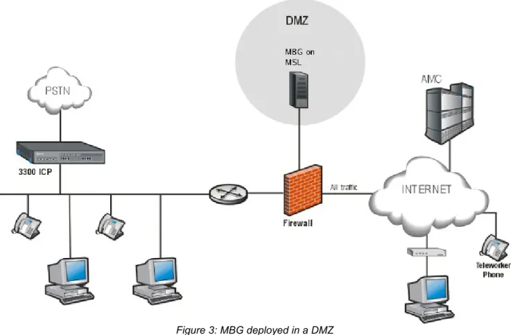
Mitel Border Gateway in a DMZ
The Mitel Border Gateway can also be deployed behind a customer-provided or customer-managed firewall as shown in Figure 3. This firewall must have 3 network interfaces (ports): WAN, LAN, and DMZ. Two-port firewalls are not supported. It should also be noted that some “DSL routers” with “DMZ” port forwarding are simply two-port NAT devices and should be treated as any other two-two-port firewall. Deployment of the Mitel Border Gateway behind such devices is not supported.
MBG requires one network interface and two addresses for this configuration. The interface must be configured with a static address allocated from the DMZ network range. This is typically an RFC 1918 “private” address. The enterprise firewall must be configured with an address allocated from the public/Internet range. This address must be:
1. reachable from the public network/Internet 2. reachable from the internal network/LAN
3. able to reach the internal network/LAN
4. preferably dedicated solely to MBG, but also see Port-forwarding firewalls
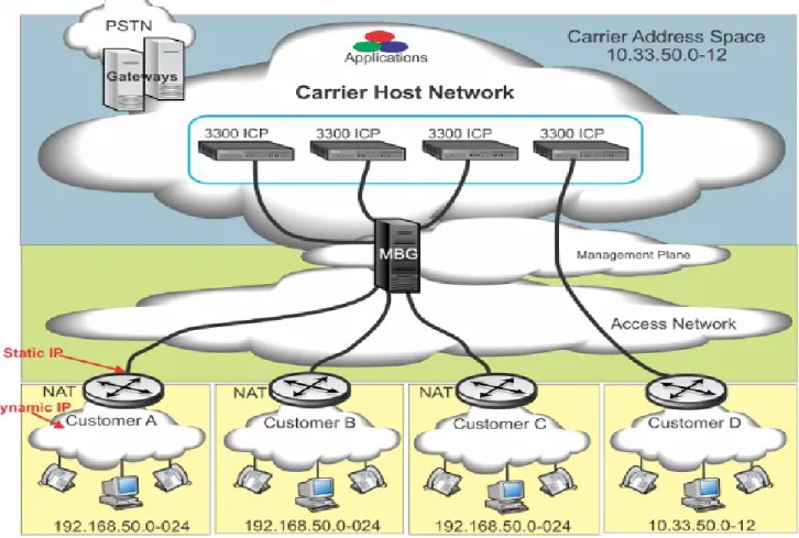
2.3 NAT Traversal for MICD
In a multi-tenant MICD install, it is possible to find tenant sites with overlapped network ranges, and without NAT at the customer edge network. In this case, MBG can be used to perform NAT traversal between the tenant sets and the MICD solution.
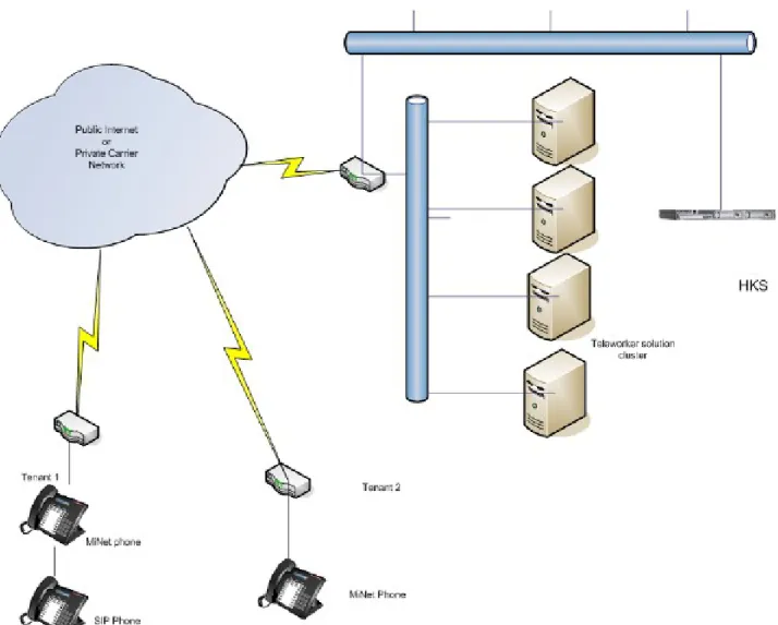
2.4 Secure Gateway for Broadview Networks silhouette HKS
The Broadview Networks hosted key system provides service to various tenants across leased lines, MPLS circuits, or the Internet from a common carrier. Customers are provided with either MiNet or SIP sets, and the MBG acts as a Session Border Controller for both protocols. DNs are unique within each tenant but may overlap between tenants.
Note: Please contact Broadview Networks to determine which MBG versions are compatible with silhouette, and for all support inquiries.
2.5 Secure Recording Environment
When MBG is provisioned with call recording licenses, it can provide a secure man-in-the-middle for call recording. This mode is supported only in a LAN environment.
It is advisable to disable MiNet restrictions on the MBG server providing call recording service, as having all LAN sets authenticate through MBG is likely not required.
Teleworker sets connected through an MBG at the network edge can be recorded as well, by configuring the edge MBG such that the desired sets point to the LAN MBG as if it was an ICP.
MBG Deployed on the LAN for Call Recording
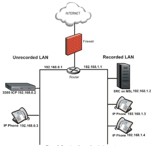
When possible, Mitel recommends deploying the MBG call recording server on the same LAN segment as the ICP(s) with which it will be working. However, it is often practical to use a separate segment if not all devices should be recordable.
Figure 6 shows one sample configuration that could be used. IP phones that are to be recorded are on the same LAN segment as the MBG server. DHCP is enabled in MSL, and MBG provides DHCP configuration such that the sets use the MBG server as their TFTP server and as their ICP. MBG then proxies the set registrations to the real ICP on the other segment. Sets on a different LAN segment using the MCD DHCP server connect directly to the MCD and are therefore not recordable.
As an alternative to changing the network topology, each set that should be recordable can be individually programmed to connect to the MBG. Hold down the “7” key and put each set into Teleworker mode. At the prompt, enter the IP address of the MBG.
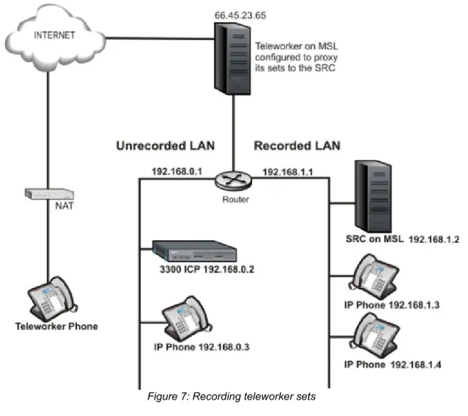
MBG servers can be chained together to allow recording of remote teleworker phones. Figure 7 below shows an example of a teleworker set connecting through the edge MBG to an MBG server for call recording (and finally to the MCD), so that it can be recorded along with the sets on the Recorded LAN. To configure this scenario, an “ICP” entry is added to the edge MBG containing the IP address of the LAN MBG used for recording. All remote sets that should be recordable must be configured with that “ICP”. The recording MBG will then proxy the remote sets to their real ICP.
Note: CIS softphone (Contact Center) can function properly in this configuration. However, only the signaling and voice should be proxied through the call recording MBG. Additional applications protocols should be proxied directly from the edge MBG to the CIS server.
Warning: This is the only supported way to have both teleworker sets and call recording of LAN sets. Combining teleworker service and call recording of LAN sets on a single server is not supported.
2.6 SIP Trunking
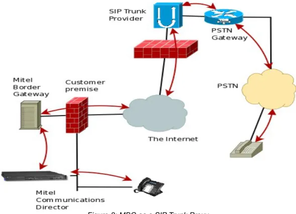
MBG introduced support for SIP trunks in release 5.1. The SIP trunk is established from the MCD to the SIP trunk provider, using MBG as a SIP-aware firewall and proxy, as shown in Figure 8 below. MBG's SIP trunk service provides:
• NAT traversal of media and signaling
• Media anchoring for the remote provider, regardless of the internal device
• SIP adaptation and normalization to improve interoperability
• Protection from malformed & malicious requests, various types of attack, and request flooding
When providing SIP trunk service, MBG can be deployed either in the DMZ of, in parallel with, or in place of an existing firewall.
Some of the key benefits of using SIP trunks are:
• consolidation of capacity; all trunks come to one location, calls routed to branch offices over MPLS or VPN links already in place
• increased simplicity for bandwidth management
• local phone numbers from anywhere in the world to permit customers to reach the company in question easily
• cheaper toll-free service in most cases • cost savings over PRI/T1/POTS lines
• increased resiliency with the potential for disaster recovery configuration
2.7 Daisy-Chain Deployments
“Daisy-chaining” is a technique of pointing one MBG at another that can work around certain bandwidth and routing restrictions. The servers are configured such that all traffic between the sets and ICPs traverses all MBG servers in series, like following links in a chain.
A “daisy-chained” MBG is one that is configured to accept all incoming requests (authentication is disabled) and pass them “upstream” to another MBG, where the standard authentication is performed.
Note: In this context, “upstream” refers to the direction approaching the ICP on the LAN.
Warning: Daisy-chaining is only supported for MiNet and SIP phones. SIP trunking and remote applications have not been formally tested with MBG daisy-chain deployments.
The two main applications of daisy-chaining are to comply with certain IT deployment policies and to reduce bandwidth for remote sites.
Special IT Policy Deployment
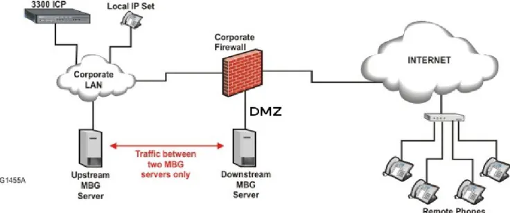
Daisy-chaining the DMZ MBG server to a LAN MBG server minimizes the scope of the firewall rules required to facilitate communications between them. The firewall administrator can permit traffic only between those two servers instead of across the entire LAN where sets may be located.
This configuration places the downstream server in the DMZ and the upstream server on the LAN. The servers should use the network profiles of DMZ mode and LAN mode, respectively.
Note: Authentication should be disabled on the downstream (DMZ) server, and adds/changes should be made only on the upstream (LAN) server.
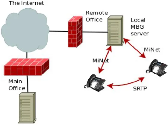
Reduced Bandwidth for Remote Sites
If MBG is providing access for a remote office environment where the users often call one another, an MBG server can be provided on site and daisy-chained to the MBG server at the main office. This is not needed for MiNet to MiNet calls behind the same remote NAT because the MBG local streaming feature will handle that case. However, this deployment can be used to keep MiNet to SIP calls in the remote office. This configuration, illustrated in Figure 10, can save bandwidth on the link between the remote and main offices.
The upstream server can be deployed in either a Gateway or a DMZ configuration.
Warning: Management of all remote office sets must be done on the upstream (main office) server only. When the downstream server is put into daisy-chain mode, it will automatically disable all MiNet and SIP connection restrictions, and pass all connection attempts up to the upstream server for authentication. The remote office (downstream) MBG can also be configured for either a Gateway or DMZ deployment. Note that there is no restriction on the location of the remote office sets; they do not have to be on the LAN. It may be desirable to configure certain teleworker sets to connect to remote office MBGs (rather than the main office MBG) in order to cause direct streaming of those teleworkers' calls to sets in the remote office. This case requires Local streaming to be enabled on the upstream (main office) server.
It is even possible to deploy multiple downstream MBG servers at different remote offices. If upstream (main office) server has Local Streaming enabled, calls within each remote office remain local to that office: signaling
still flows back to the main office, but voice streams for calls between offices will only traverse the path between the two MBGs. This minimizes bandwidth use on the main office's connection.
Caveat: All MBG servers in the daisy chain must be at the same release.
Refer to the MBG Installation and Maintenance Guide for a full description of setting up daisy-chaining.
2.8 MBG in MAS
There are two supported deployments of MBG in MAS: on the LAN and on the network edge (Gateway mode). Deployment in the DMZ is not supported.
MAS on the LAN
The safest way to deploy MBG is to leave MAS and its applications on the LAN, and deploy a second server running MBG (either standalone or single-app MAS) in the DMZ or in Gateway mode at the network edge. Remote access to the LAN MAS can be provided via Web Proxy on Internet-facing MBG. If centralized
management is desired, the two MBG applications can be clustered. All changes made on the LAN server will be reflected on the edge MBG. Refer to the MAS documentation set for details on clustering MBG with MAS.
MAS on the Network Edge
Although Mitel recommends the dual server approach for maximum security, a single MAS server with all applications can be deployed in Gateway mode at the network edge. In this configuration, all administrative and end-user web interfaces and all services are directly reachable from the public network; Web Proxy is not required to reach them.
2.9 MBG in vUCC
The vUCC product combines MAS and MCD on one virtual machine. Refer to the vUCC Deployment Guide for a description of supported vUCC configurations.
Support for an additional MBG deployment configuration is introduced for vUCC environments only because of specific IT constraints imposed by some cloud providers. For vUCC deployments only, MBG in server-gateway behind an existing firewall is supported with the constraint that phones must not connect to the MBG from the LAN side of the firewall. That is, this configuration is only supported for phones connecting to the MBG WAN interface via the existing firewall WAN interface.
2.10 Partial Service Configurations
All MBG services are not available in all supported configurations. This section identifies for each MBG service configurations where the service is not supported at the time of writing. In some cases the service may be technically possible but not currently supported pending further testing or to reduce complexity.
MBG provides the following services: • Remote MiNet IP Phones
◦ Connecting to MBG in vUCC is not supported for LAN phones.
◦ Connecting to MBG in MAS on the LAN is not supported for Internet phones. • Remote SIP IP Phones
◦ Connecting to MBG in vUCC is not supported for LAN phones.
◦ Connecting to MBG in MAS on the LAN is not supported for Internet phones.
◦ The SIP Teleworker service is not available with MBG for the following ICP type: 5000 • SIP Trunking
◦ Connecting to a SIP trunk service provider from MBG in MAS on the LAN is not supported. • Call Recording
◦ Connecting to MBG in vUCC is not supported for LAN phones.
◦ Recording calls with MBG in MAS on the network edge is not supported for LAN phones. ◦ Recording calls with standalone MBG on the network edge is not supported for LAN phones. ◦ Call recording is not available with MBG for the following ICP types: 5000, silhouette
• Remote Proxy Services
◦ Remote Proxy Services are not available with MBG in MAS. ◦ Remote Proxy Services are not available with MBG in vUCC.
3 Common Requirements
This section provides general guidance common to all types of deployments and all services. Please read it carefully.
3.1 Supported ICP Versions
At least one of the following compatible ICP products is required to use Mitel Border Gateway:
• Mitel Communications Director (MCD) release 4.0 or later. (Includes vMCD, MICD, 3300 platforms.) • Broadview Networks silhouette release 4.0.0.3 or later. (Contact Broadview for the required MBG
version.)
• Mitel 5000 CP. (SIP Trunking only for release 5, add MiNet Teleworker with release 6)
3.2 Administrative Access
MBG provides a web-based management GUI for normal administration, log access, etc. This service can be accessed with any of the following supported web browsers:
• Mozilla Firefox 3.0 or higher
• Microsoft Internet Explorer 6.0 or higher
Although not officially supported, the following browsers are tested occasionally and should also work: • Google Chrome
• Apple Safari
• any browser using the Mozilla Gecko engine or the Apple WebKit engine
Note: the MBG GUI requires a browser that supports JavaScript. The built-in MSL text-mode browser does not support JavaScript and cannot be used to manage MBG.
Some troubleshooting or advanced configuration requires command-line access. SSH is the only supported mechanism to reach the MSL command line remotely. On Microsoft Windows, Mitel recommends the use of
PuTTY (a small, free SSH client). OpenSSH is included with Apple Mac OS X (open Terminal and type “ssh”), and is included with or available for most flavors of Unix.
3.3 Firewalls (DMZ deployment)
MBG can be deployed into the DMZ of most third-party firewalls. However, a compatible firewall must have certain characteristics.
1. The firewall must provide at least three interfaces: external network, internal network, and DMZ.
2. The firewall must provide static 1:1 NAT between an externally-visible address and the DMZ address of the MBG server.
3. The public address used for MBG must be a static IP address visible from the external network
(Internet). This should be a separate address from the external IP address of the firewall, although some firewalls that support port forwarding may allow sharing the address. It is vital that this address actually be static as any change of the address will cause remote sets to lose connectivity.
4. The firewall must preserve the TCP and UDP port numbers in packets exchanged between the MBG and the external network. In other words, only the address field may be changed.
NIC should be given an address on the DMZ network. The firewall will map between this address and the external address used for MBG.
Details of the protocols that must be configured in the firewall are provided in Firewall Configuration. Particular attention should be paid to the requirement that all UDP ports >= 1024 on the LAN be permitted to reach the public IP of the MBG server.
Warning: Failure to configure the firewall properly will result in audio problems (typically one-way audio).
Known Issues
Checkpoint “NG” Firewalls
Checkpoint “NG” firewalls (e.g. FireWall-1 NG) have a feature called “Smart Connection Re-use” that may interfere with older MiNet sets and some SIP sets that use a fixed source port for their outgoing connection. The feature should be disabled with older sets or if set connections to the MBG server cannot be maintained.
It is not a problem with newer sets that randomize the source port used for each new connection.
Port-Forwarding Firewalls
Use of MBG server with a port-forwarding firewall (where the external address of the firewall is shared between the Mitel Border Gateway and other applications) is supported by MBG version 3.0 and higher. The firewall device must have at least 3 interfaces (external, internal, DMZ). This allows for a single external IP address to be assigned to the firewall. It does not eliminate the need for a separate DMZ network.
This special configuration is identical to a normal DMZ deployment with the exception that the MBG’s publicly-visible IP address will be the same as the firewall’s publicly-publicly-visible address (that is, the single public IP address is shared).
Warning: Two-port firewall devices that simulate a DMZ through port forwarding are not supported, even if the device allows multiple external IP addresses.
SIP-Aware Firewalls
Many firewall devices today understand the SIP protocol and include some type of NAT traversal or rewriting of SIP packets. When MBG is used for connecting SIP clients (sets) and trunks, Mitel recommends turning off any SIP features of the main firewall. At best, it is redundant to have two devices performing the same job. In worse cases, they interfere with each other.
UDP Flood Protection
UDP flooding protection and VoIP applications utilizing RTP do not work well together. It is recommended that UDP flooding protection in firewalls in the voice path be disabled.
Firewall Configuration Common to all Services
In a DMZ deployment, it is recommended that the administrator configure their firewall in the following way, regardless of the MBG feature set in use:
• Allow return traffic from established TCP connections • From the server to the Internet allow traffic with
◦ protocol TCP, destination port 22 (communications with Mitel AMC)
◦ protocol UDP, destination port 53 (and return traffic) (DNS)
• From anywhere to the server allow traffic with
◦ protocol UDP, destination port range 20000 to the configured upper bound (31000 by default) (RTP)
• From the server to anywhere allow traffic with ◦ protocol UDP, destination port >= 1024 (RTP)
Note: This list is not exhaustive. Refer to the sections on individual services for the required ports and protocols of each. A more comprehensive set of firewall rules is given in Appendix A: Firewall Configuration Reference.
4 Remote Phone Access
A major purpose of the MBG is to allow remote MiNet IP and/or SIP phones to connect to the office PBX over an insecure wide-area network such as the Internet, as if they were physically in the office. Most current (and many older) models of IP sets are supported by MBG. However, please refer to the Remote IP Phones Configuration Guide for guidance on specific models. Most SIP devices, including all Mitel-branded SIP devices, can also be configured to work with MBG.
This section provides general guidelines for the Teleworker service. Please refer to Sizing Your Installation to determine detailed requirements and performance limits.
4.1 Remote Site Requirements
Router
A set in a remote site (such as a home or branch office) is assumed to be part of a wired or wireless LAN behind a simple NAT router that provides access to the Internet, typically through a DSL or cable modem.
Mitel IP and SIP phones generally require a 10/100/1000 Mbps Ethernet connection, although some models can be configured for WiFi. (Refer to the device's documentation for configuration details.) All devices expect a TCP/IP network regardless of the link-layer technology.
The remote site router must provide, at minimum:
• 10/100/1000 Mbps Ethernet with RJ45 connectors, for Mitel sets and connection to cable/DSL modem • NAT from the internal network to the external network
• passthrough of UDP and TCP protocols, including TFTP
The router should provide DHCP service, offering at least an IP address and default gateway. However, devices can be programmed with static IP addresses and settings in the absence of DHCP.
The router may need to support PPPoE/PPPoA when used with a DSL modem, and must be configured with the user name and password provided by the ISP.
The router may need to support Authenticated DHCP (client) when used with a cable modem, and must be configured with the user name and password provided by the ISP.
If WiFi sets are to be used, the router or a separate WiFi access point must also provide 802.11 b/g/n.
The router must control the Internet connection in order for multiple devices to share the connection. When using desktop phones, the use of USB PPPoE/PPPoA modems, USB 3G/4G modems, etc are not supported as they do not provide a port to plug in the phone. However, such devices can be used with softphones running on the PC if no other devices need to share the internet connection of the PC. A similar caveat applies to any service that requires software to be loaded on the PC, such as AOL Broadband. It cannot be used with a desktop device, but can possibly be used with a softphone application such as Mitel Unified Communicator Advanced.
Note: the remote site may have a dynamic IP address. However, if the address changes during a call, the call will drop and all devices at the site must re-register with MBG to restore service.
VPN Connectivity
Connecting a PC to the second Ethernet port on the back of a Mitel IP phone does not provide the PC with a VPN connection to the office network. That connection must still be made by use of the organization's supported VPN client software. This ensures that security of the corporate network is maintained when using Mitel Border Gateway.
A gateway-to-gateway VPN can be constructed between branch offices (or homes) and the main office, if desired, such that all the PCs in the remote office have full access to the corporate LAN. However, Mitel advises that only non-voice traffic be routed across the VPN; voice traffic between sets and the MBG should traverse the Internet whenever possible. Routing real-time voice protocols across a VPN can result in degraded service. Mitel Standard Linux, upon which MBG runs, does provide a PPTP VPN service. If desired, the MBG server can be used as a VPN concentrator for access to the corporate network. However, a VPN is not required to use the features of MBG itself. For more details, please see the Mitel Standard Linux Installation & Administration Guide (available from http://edocs.mitel.com/).
Using an Existing VPN
Using the Mitel Border Gateway does not affect any existing VPN client software (e.g. IPSEC road warrior connection) installed on the remote PC. The PC should be connected to either the second Ethernet port of the IP phone or directly to the router and the existing software should be used as before.
Note: VPN (e.g.IPSEC) pass-through must be supported by the router at the remote site.
Corporate Firewall & Network Configuration for VPN Access
The corporate office firewall may need to be reconfigured to allow other traffic from the MSL server to the internal network if the MSL server is used as a VPN server. The ports and protocols required will depend on the
applications used by the client PCs and this configuration is outside the scope of this document.
More information on firewall configuration can be found in 3.3 Firewalls (DMZ deployment) and Appendix A: Firewall Configuration Reference.
Bandwidth Requirements for the Remote Site
This section analyzes bandwidth requirements of the remote site using the Mitel Border Gateway. Typically, there will be other requirements for Internet access, and these requirements (such as mail, web browsing,
e-commerce) must be provisioned as well. Failure to provide sufficient bandwidth for all Internet activities may compromise the quality of service provided by the Mitel Border Gateway.
The table below shows examples of bandwidth required for various types of remote media streams. Voice If compression (G.729a) enabled: 24 Kbps (bi-directional)
If compression not enabled (G.711): 80 Kbps (bi-directional) MCA Collaboration 192 Kbps (bi-directional)
UCA Video 256 Kbps – 1600 Kbps (bi-directional) UC360 Video 512 Kbps – 1500 Kbps (bi-directional)
Table 1: Bandwidth requirements of a single remote teleworker device
This table does not consider bandwidth requirements for PCs or other devices, which must be provisioned in addition to the IP Phone. If there is insufficient bandwidth, symptoms experienced by the IP phone user may include degraded voice quality, slow response, service interruption or loss of service. It also does not consider bandwidth requirements for additional applications. Please see the section Additional Application Requirements
for more information.
Note: A video call requires 10 to 20 times more bandwidth than a compressed audio call even when configured with the lowest bandwidth settings.
A remote UC360 connecting to MBG over the Internet should be configured to disable the H.264 High Profile codec and to disable the Dynamic Bandwidth Allocation option. A video conference should not be initiated from a UC360 on the Internet because it would serve as a bridge and dramatically increase bandwidth requirements for the call.
Video calls between UCA 6.0 and UC360 2.0 are supported through MBG but they do not negotiate bandwidth at the time of writing. For example, a UCA client on the Internet will receive video at the rate configured on a
UC360 on the LAN even if the UCA is configured to use low bandwidth. This will be rectified in a future release of UCA and/or UC 360.
MCA voice and video conferencing between MCA clients via the MCA server is also supported through MBG. The bandwidth usage per video stream is configurable on the MCA client. An additional consideration is that an MCA client can receive multiple video streams, one for each video participant in the conference. That number can be reduced at the MCA client by minimizing or closing video windows.
For details and current values, please see the engineering guidelines for the devices/applications referenced as examples here (available from http://edocs.mitel.com/).
Bandwidth Usage and ISP Quotas
Many Internet Service Providers set quotas on the amount of IP bandwidth per month. As an aid in predicting whether a specific quota will be exceeded, this section provides the necessary data and a sample calculation. Assumptions:
• Signaling channel requires 1 KByte per minute (average), based on 6 calls per hour, business usage, 15 minutes per hour
Bandwidth Required Hourly Usage (100%) Monthly Usage (100%)
Signaling (MiNet) 1 KB/minute 60 KB 43.2 MB
Signaling (SIP) 1.75 KB/minute 105 KB 75.6 MB
G.711 voice stream (IP),
20ms 80 kbps 36 MB 25.92 GB
G.729a voice stream (IP),
20ms 24 kbps 10.8 MB 7.78 GB
Table 2: Bandwidth usage vs time for an IP or SIP phone
Note: 20ms is the default RTP frame size, but the value is configurable in the Mitel Border Gateway administration panel.
The data in the above table can be used to:
1. estimate the available call time given a quota
2. estimate the monthly bandwidth requirement for a given call volume Example 1: Estimating Available Call Time
Given an ISP quota of 2 GB/month and continuous use:
Call hours of G.729a = (2000 MB - 43.2 MB) / 10.8 MB per hour = 181 hours Call hours of G.711 = (2000 MB - 43.2 MB) / 36 MB per hour = 54 hours
Given the same 2 GB/month quota, and usage of 15 min/hr, 12 hours per day, 7 days per week: Call hours of G.729a = (1448 hours or more than 1 month)
Call hours of G.711 = (432 hours or roughly 18 days) Example 2: Estimating Monthly Bandwidth Requirements
Given a user that averages 4 hours of phone calls per day, for 22 workdays in a month:
Bandwidth Usage for G.729a = 43.2 MB + (10.8 MB x 4 hr per day x 22 days) = 994 MB
Bandwidth Usage for G.711 = 43.2 MB + (36 MB x 4 hr per day x 22 days) = 3200 MB or 3.2 GB
Configuring the Remote Site Firewall
If the remote office has a firewall, it must be configured to allow the IP or SIP phone to connect through it to the Mitel Border Gateway. The simplest approach is to permit all connections to or from the MBG's IP address. A second very simple approach is to permit all outgoing connections and any responses to them. By default, most
small office and home NAT routers allow outgoing connections and responses to those outgoing connections. Sites with more restrictive security policies may wish to use the following rules:
• Allow a bi-directional TCP connection to destination ports 6801 and 6802 on Mitel Border Gateway IP address
• Allow bi-directional TCP connections to destination ports 3998 and 6880 on the Mitel Border Gateway IP address (for 5235, 5330, 5340 and Navigator set features)
• Allow incoming UDP from source ports 20000 to 31000 on Mitel Border Gateway IP address • Allow outgoing UDP to destination ports 20000 to 31000 on Mitel Border Gateway IP address
• Allow bi-directional TCP connections to destination ports 36005, 36006, 36007, 36008 and 37000 on the Mitel Border Gateway IP address, if using UCA.
• Allow incoming and outgoing UDP to port 5060 on the Mitel Border Gateway IP address, if SIP support is desired
4.2 TFTP Behavior
Mitel IP phones require a TFTP server that holds their set firmware and HTML applications. For remote phones, this TFTP service is provided by MBG.
Previous versions of MBG bundled a version of the HTML Applications and served them directly. This caused some trouble with keeping versions in sync, especially with multiple ICPs. Since release 7.0, MBG does a proxy request to the appropriate ICP instead.
When an IP phone connects to its ICP, the ICP (MCD) may issue a File Download directive over the SAC protocol connection. MBG intercepts these directives and downloads the file on behalf of the remote set. It then sends a modified directive to the set instructing it to download the cached file from MBG. This ensures that the set receives the same file that it would if it were directly connected to MCD. MBG will check periodically for updated HTML application files at the ICP. The frequency of checks depends on the feature set supported by the ICP. It could be as often as 10 minutes, and as infrequent as 24 hours.
Note: MBG's file downloader does not know about any ICPs until sets connect to MBG and thus get connected to an ICP. This step happens after a set has already retrieved its firmware load via TFTP. Due to that, set firmware loads are still bundled with MBG and are not fetched from the ICPs.
4.3 Firewall Configuration for Remote MiNet Devices
When MBG is deployed in the DMZ, the corporate firewall protecting the DMZ requires the following rules (in addition to the common rules found in Firewalls (DMZ deployment)):
From the Internet to the MBG server:
• allow protocol TCP, destination ports 6801, 68022, 3998 and 6881
• allow protocol UDP, destination port 20001 (and return traffic) From the MBG server to the LAN (or just ICPs):
• allow protocol TCP, destination ports 6800, 6801, 6802, 3998, 3999 and 6880 • allow protocol UDP, destination port 20001 (and return traffic)
Note: This is a minimal configuration. Refer to Appendix A: Firewall Configuration Reference for the full set of rules and optional settings.
4.4 Configuring MBG for Remote SIP Devices
Remote SIP Device Limitations
MBG cannot yet load-balance SIP devices. In general, resiliency for a SIP device can be achieved through external DNS by configuring multiple “A” records for the FQDN of the MBG, or by configuring SRV records. Refer to the documentation of the remote SIP devices for guidance on configuring resiliency.
Tuning Global Parameters
The default values for all parameters assume a Teleworking installation, with SIP devices being used over the Internet. In a LAN context, these parameters will work correctly but may be slightly aggressive.
By default, MBG sends a SIP “Options” request to every connected device at an interval of 20s (“Options
keepalives”). The responses from these requests reset the idle timer for each connection. Each connection has a 300s (5 minutes) idle timeout, so the most important thing to remember is that the MBG server must see valid SIP traffic from each device within the 300s interval. A device that times out due to inactivity is disconnected and becomes out of service.
On a “quiet” network it is sufficient to disable gapped registration and raise the options interval to its maximum value (180s at this time). If all remote SIP devices send their own keepalives or re-register at an interval less than 300s, MBG's Options Keepalives can be turned off.
DNS Support
While SIP clients can address MBG by its IP address, Mitel recommends the use of a fully-qualified domain name (FQDN) in the public Domain Name System (DNS) that resolves to the public IP of the MBG server. Advantages:
• The IP address of the MBG server can be changed, and the clients will not need to be reconfigured. • DNS can provide a certain level of resiliency in case an MBG server experiences any kind of service
outage. Simply configure the FQDN to resolve to multiple MBG servers. Please note that MBG cannot control how a SIP device behaves when it receives multiple IP addresses in a DNS response.
Note: A remote SIP message will be recognized as being addressed to MBG if the IP in the URI is one that MBG owns, or the FQDN in the URI either resolves to an IP that MBG owns, or is one of the configured “Allowed URIs” in the “SIP options” section of the Configuration tab.
Warning: A SIP server requires functional DNS even if all devices are configured to use IP addresses instead of FQDNs. MBG is no exception. Failure to provide MBG with a working DNS resolver or preventing MBG from reaching the Internet DNS root servers can cause delays or failures in call setup.
4.5 Firewall Configuration for Remote SIP Devices
When MBG is deployed in the DMZ, the corporate firewall protecting the DMZ requires the following rules (in addition to the common rules found in Firewalls (DMZ deployment)):
From the Internet to the MBG server:
From the MBG server to the LAN (or just ICPs):
• allow protocol UDP, destination port 5060 (and return traffic)
Note: This is a minimal configuration. Refer to Appendix A: Firewall Configuration Reference for the full set of rules and optional settings.
5 SIP Trunking
5.1 Overview
A “SIP trunk” in the context of MBG is simply a pair of endpoints, defined by their IP addresses and signaling ports. One of the endpoints is usually your ICP (MCD (3300 ICP) or 5000 CP), and the other is your SIP provider’s firewall or SBC.
A trunk can have any number of “channels,” each of which corresponds to an active media stream. A channel license is required for each active channel, so you will need enough channel licenses to cover the maximum number of active calls. As an analogy, an ISDN PRI link contains 23 B channels for audio and one D channel for signaling, and can carry a maximum of 23 simultaneous calls. This would be equivalent to a SIP trunk with 23 channel licenses.
Note: On the MCD (3300 ICP), the MBG is configured as an outbound proxy in the Network Element form. Warning: In the 5.X releases, the SIP trunk connector listened on UDP port 5064 by default. As of MBG 6.0 the SIP connector can handle device endpoints and sip trunks, so UDP port 5060 is used for both devices and SIP trunks. The Legacy Connector can no longer be re enabled as of MBG 8.0. If UDP port 5064 is in use then you will need to contact your SIP Trunk provider to have their equipment changed to use MBG's UDP port 5060 before upgrading MBG to 8.0.
Warning: A SIP server requires functional DNS even if all devices are configured to use IP addresses instead of FQDNs. MBG is no exception. Failure to provide MBG with a working DNS resolver or preventing MBG from reaching the Internet DNS root servers can cause delays or failures in call setup.
5.2 Bandwidth Requirements
Please see the section Sizing Your Installation on page 40.
5.3 Resilient Trunk Configuration
This section describes a sample resilient SIP trunk configuration using two ICPs and two MBGs. First, configure resiliency between the ICPs.
On ICP “A”:
• Create a Network Element Assignment for MBG “A” (as type Outbound Proxy) and another for the SIP provider’s SBC (as type Other). Create a SIP Peer Profile for the SBC using MBG “A” as the Outbound Proxy.
• Add a Network Element Assignment for MBG “B” (as type Outbound Proxy) and create another SIP Peer Profile for the SBC using MBG “B” as the Outbound Proxy.
• Program a Route List in ARS with SIP peer “A” and SIP peer “B”. Then program ARS Digits Dialed such that outgoing calls use the new route list.
Repeat the above configuration on ICP “B”, except reverse the order of trunks in the route list so that “B” comes before “A”.
Configure MBG clustering. On the master MBG, go to the “ICPs” tab and add both ICP “A” and ICP “B”. On the “SIP Trunking” tab, configure a trunk profile for the remote SBC. Add a single routing rule of “*” with ICP “A” and ICP “B” as the targets of the rule. This configuration will propagate to the secondary MBG.
Incoming calls from the SBC will arrive at either MBG A or MBG B. From there, the MBG will route them to ICP A if it is up, or to ICP B if ICP A is down. Outgoing calls from either ICP can be routed through either MBG.
5.4 DNS Support
While the ICP can address MBG by its IP address, Mitel recommends the use of a fully-qualified domain name (FQDN) in the public Domain Name System (DNS) that resolves to the public IP of the MBG server.
Advantage:
• The IP address of the MBG server can be changed, and the ICPs will not need to be reconfigured. Note: An ICP SIP message will be recognized as being addressed to MBG if the IP in the URI is one that MBG owns, or the FQDN in the URI either resolves to an IP that MBG owns, or is one of the configured “Allowed URIs” in the “SIP options” section of the Configuration tab. Typically, the hostnames youadd to the “Allowed URIs” list will be for the SIP service provider's session border controller or service domain.
Warning: A SIP server requires functional DNS even if ICPs are configured to use IP addresses instead of FQDNs. MBG is no exception. Failure to provide MBG with a working DNS resolver or preventing MBG from reaching the Internet DNS root servers can cause delays or failures in call setup.
5.5 Firewall Configuration for SIP Trunking
When MBG is deployed in the DMZ, the corporate firewall protecting the DMZ requires the following rules (in addition to the common rules found in Firewalls (DMZ deployment)):
Note: Please remember to turn off any UDP flooding protection and any SIP features of the DMZ firewall. From the Internet to the MBG server:
• allow protocol UDP, destination port 5060 (and return traffic) From the MBG server to the LAN (or just ICPs):
• allow protocol UDP, destination port 5060 (and return traffic)
Note: This is a minimal configuration. Refer to Appendix A: Firewall Configuration Reference for the full set of rules and optional settings.
6 Call Recording
MBG includes the ability to act as a secure man-in-the-middle for SRTP voice streams, enabling a third-party call recording solution to tap calls by using MBG’s SRC interface.
Please see the section on Sizing Your Installation to determine performance limits and resource requirements.
6.1 Call recording vs. Local streaming
Mitel Border Gateway supports both Local Streaming and Call Recording, both of which can be enabled or disabled for individual users. These options are not compatible.
Local Streaming is a generally desirable feature that reduces bandwidth needed for voice/video calls by allowing the RTP stream(s) to bypass the MBG when two devices are able to communicate directly. However, this means such calls cannot be recorded. If both Local Streaming and Call Recording are enabled on a device, Call Recording wins. All streams to and from that device will go through MBG so they can be recorded.
6.2 Indirect Call Recording
Indirect Call Recording (ICR), introduced in MBG 7.1, is a feature supported by Mitel's 53XX series IP sets and MCD software release 5.0 SP1 and up. It also has only limited support from CRE vendors.
With ICR in place, SRC can support recording of any supported sets that are connected to any supported MCD without having to reconfigure the sets to connect through SRC, as is the case with “direct” call recording. SRC can be configured with a mix of both ICR and "direct" call recording. This would be required if non-supported sets or MCDs are deployed.
Using ICR allows for some cost reductions and more network flexibility in certain call recording deployments. It is especially applicable for network deployments where centralized call recording is desired in a network situation where remote, WAN-connected sets are connected to remote office MCD's.
When MBG is deployed in the DMZ, the corporate firewall protecting the DMZ requires the following rules (in addition to the common rules found in Firewalls (DMZ deployment)) to support Indirect Call Recording:
From the MBG server to the ICPs:
7 Additional Application Requirements
MBG allows the use of several supported applications from remote sites, just as it allows use of IP phones. When MBG is deployed in the DMZ of a third-party firewall, that firewall must be configured to allow connections from these applications.
This section, plus the common rules in Firewalls (DMZ deployment) on page 15, gives a minimum configuration for each supported application. Refer to Appendix A: Firewall Configuration Reference for the full set of firewall rules.
7.1 Unified Communicator Advanced (UCA) v4.0+
Warning: MBG 7.0 required a port-forwarding rule for port 36008 that directed traffic to the UCA server. After upgrading to MBG 7.1 or higher, this rule must be removed from the MSL Port Forwarding panel. The following additional rules are required, excluding the UCA softphones:
From the Internet to the MBG server:
• allow protocol TCP, destination ports 5269, 36005 – 36008 (inclusive) From the MBG server to the LAN:
• allow protocol TCP, destination ports 80, 443, 5060, 5269, 36008
Note: When UCA server is behind MBG, remote UCA clients require access via Web Proxy for UCA 5.1 and above. See 7.3Web Proxy for additional firewall rules.
UCA clients also include MiNet and SIP softphones. For additional firewall rules covering the UCA softphones see 4.3 Firewall Configuration for Remote MiNet Devices and 4.4 Configuring MBG for Remote SIP Devices. MBG 8.0 includes two additional connectors to help with specific kinds of UCA SIP softphone connectivity issues that may be experienced in some deployments due to improper handling of SIP UDP by some NAT firewalls. These MBG connectors allow the configuration on selected UCA SIP softphones to be changed from SIP UDP signaling to use SIP TCP or SIP TLS signaling (TLS preferred). When the selected UCA SIP softphone connects to MBG on TCP or TLS from the Internet, the MBG bridges it internally to the SIP UDP connector used by default for the unmodified UCA SIP softphones.
The following additional rules are required for UCA SIP softphone signaling over TCP or TLS: From the Internet to the MBG server:
• allow protocol TCP, destination ports 5060, 5061
7.2 Mitel Contact Center
The following additional rules are required: From the Internet to the MBG server:
• allow protocol TCP, destination ports 35001 – 35008 (inclusive), 36000 – 36004 (inclusive) From the MBG server to the LAN:
• allow protocol TCP, destination ports 80, 443, 1443, 5024 – 5026 (inclusive), 5030, 7001, 7003, 8083, 8084, 8188, 42440
7.3 Web Proxy
The following additional rules are required, at minimum: From the Internet to the MBG server:
• allow protocol TCP, destination port 443 From the MBG server to the LAN:
• allow protocol TCP, destination port 443
Special consideration for MCA through Web Proxy
In addition to https traffic, MCA requires passthrough of its ConnectionPoint connection. It will arrive at the firewall on TCP port 443, on a dedicated IP address for MCA (see the MAS documentation for full details), and the firewall must forward the traffic to the Web Proxy server (MBG) at whatever listen port is configured in Web Proxy.
From there, the traffic will be forwarded to the MCA server on the LAN on TCP port 4443. The required rules are: From the Internet to the Firewall:
• allow protocol TCP, destination port 443 on the MCA IP address From the Firewall to the Web Proxy (MBG):
• allow protocol TCP, destination port A, where A is the listen port for MCA configured by the Web Proxy administrator
From the Web Proxy (MBG) to the MCA server on the LAN: • allow protocol TCP, destination port 4443
7.4 Remote Management Service
MBG Remote Proxy Services includes Web Proxy for end users and Remote Management Service for system administrators. The Remote Management Service introduced a new capability in MBG 8.0 to support remote upgrade, backup and restore of MCDs on the LAN. This feature requires enabling an FTP server on the MBG. Remote FTP clients on the external network upload MCD software to the FTP server on MBG. An MCD FTP client on the internal network downloads MCD software from the FTP server on MBG. An MCD FTP client on the internal network uploads MCD backup files to the FTP server on MBG.
Note: Remote FTP clients must use passive FTP. Active FTP will not work through remote NAT firewalls. The following additional rules are required, at minimum:
From the Internet to the MBG server:
• allow protocol TCP, source ports >1023, destination port 21, destination ports >1023 From the MCD on the LAN to the MBG server:
8 Additional Security Considerations
Due to the broad range of application types that can be deployed on the Mitel Standard Linux operating system (formerly Managed Application Server), Mitel suggests that you read the Security section of the Mitel Standard Linux Installation and Administration Guide before installing this application on the same server with other applications,
8.1 SIP Security
While the majority of traffic in MBG is encrypted, the SIP implementation is UDP-based, and unencrypted at this time. Additionally the RTP streams for SIP voice & video calls are also plain RTP, and thus unencrypted. As our SIP implementation cannot make use of SRTP at this time, calls between SIP and MiNet sets are also “in the clear”.
9 Traffic Shaping
9.1 Overview
For small businesses with a simple setup to the Internet, sharing that upstream link between voice and data can be problematic. Users in the middle of calls to the PSTN via SIP trunks, for example, will find the voice quality of their calls greatly reduced if a member of the office were to suddenly start a large download from the Internet. To mitigate these issues, MBG has the capability to prioritize the IP traffic that it is handling. This technique is commonly known as traffic shaping.
To shape traffic, MBG must be in a position to handle all traffic to the organization’s upstream link; specifically, it must be in gateway mode with a minimum of two network interfaces. In this mode, it can act as the
organization’s firewall. More commonly, however, the organization already has a firewall product of some kind, and would like to deploy MBG and use traffic shaping with a minimum of disruption. This “transparent”
deployment is possible on servers with three network interfaces.
Using MSL 9.2+ the third interface can be put into bridged mode. The bridged interface can then be connected to the WAN interface on the existing firewall. This configuration transparently places MBG between the existing firewall and the WAN, and allows MBG to prioritize the organization’s traffic, without requiring changes to the existing firewall.
9.2 Technical Details
Figure 13 below illustrates the queuing discipline that MBG uses for traffic shaping. The hierarchical nature of the algorithm allows lower priority queues to use tokens available in higher priority queues, which means that when little VoIP traffic is available, lower priority data will not be unnecessarily constrained. Thus, the customer can make full use of their available bandwidth to the Internet.
The categorization of high priority vs. low priority traffic is performed based on two criteria:
1. Source IP Address If the source IP address of the traffic belongs to any of the network interfaces on the MBG server, then it matches the first criteria. In other words, MBG must originate the traffic.
2. DSCP value The second criteria of high priority traffic is a DSCP value of 46 decimal, 0x2E hex (Expedited Forwarding). This value must be set on packets that are considered high priority. MBG will set the value for its own VoIP-related traffic.
If both of these criteria are satisfied, then the traffic ends up in the high priority queue. Otherwise, it is considered low priority and will only be permitted through the HTB queue if the high priority queue has unused tokens. This does mean that excessive high priority traffic can starve low priority data traffic. However, 10% of available bandwidth is reserved for low priority traffic (if it is present), so it should not starve completely. This reservation does not waste bandwidth: it can be “borrowed” by the high priority queue if no low priority traffic is present.
Figure 13: The Hierarchical Token Bucket Queue
10 Clustering
10.1 Overview
Clustering in this context refers to the ability of multiple MBG servers to communicate with one another via TCP, sharing data and providing the capability to manage multiple nodes thus joined as if they were a single unit. Clustering also provides load balancing for supported MiNet devices, making the job of distributing devices across servers to share workload simple and effective. Set resiliency is also used within clustering, so that supported MiNet sets which can persistently store up to four IP addresses will have their resiliency list populated based on the cluster members.
Clustering relies on a mesh of TCP connections between the nodes in the cluster. TCP port 6809 must be reachable between all nodes for cluster comms to be established. SSL/TLS is used to encrypt communications, so it is safe to use over the Internet.
Administrative access to each server in the cluster is required to establish a trust relationship between the nodes. The trust model is based on the IP addresses used to establish cluster comms. Each node is configured via the clustering tab to trust a connection coming in from a particular IP address. These addresses are shared across the cluster, so they must be reachable by all nodes involved, and any use of NAT will break the trust model. A summary of the steps to create a three-node cluster are shown below. Refer to the Mitel Border Gateway Blade Installation and Maintenance Guide for full instructions on creating a cluster.
• Create the cluster from the master node, entering the IP address of the first slave node. • Join the cluster from the first slave node, entering the IP address of the master node.
• Assuming no networking issues, the clustering tab will show established connections, and the slave node will show a backlog of events from the master (or it will finish too quickly to be seen).
• Add a node on the master, entering the IP address of the second slave node
• At this time, the first slave will receive the same data regarding the second slave via cluster comms. • Join the cluster on the second slave, entering the IP address of the master node.
• Assuming no networking issues, the clustering tab on all nodes should show the peer nodes for that node.
• The three node cluster is now established.
Once cluster communications are established, the master node will “push” data to the slaves until they are in sync with the master. Conflicting data is overwritten. Data that the master node does not have a copy of is not modified, and is not pushed to the master. Merging data is accomplished by taking ownership from each slave node (i.e. making that node the master) in turn, causing the new master to push its data to all other nodes, until all data is in sync across the cluster. Unwanted records can then be deleted from the master node.
10.2
Cluster Zones
A cluster zone is a non-overlapping subset of nodes within an existing cluster. All nodes start out in the “Default” zone. The “Default” zone can be renamed but it cannot be deleted. It is easily identified because it appears first in the zone list, and has no “delete” link. Nodes can be left in the default zone if additional zoning is not required. Additional zones can be created, and nodes can be moved to any zone. Zones can be created based on
geographic location, the intended purpose for the nodes, or whatever reason the admin chooses. The purpose of zones is to provide device affinity.
By default all MiNet sets will be associated with the default zone. By editing the set, the set may have its affinity changed to a different zone. The implications of this are as follows:
• A set’s load-balancing list of nodes will always favor nodes in its zone • The last entry in the load-balancing list will be a node from the default zone
This feature was introduced to support geographically dispersed clusters. For example, if there are three servers in North America and three in Asia, it makes little sense for Asian sets to be load balanced to North America unless all of the Asian servers are unreachable. Using cluster zones, a “North America” zone and an “Asia” zone could be created, and sets in Asia could be placed into the Asian zone. The sets in each region would then prefer the nodes in their region, reducing network latency and bandwidth use.
Similarly, zones can be created to segregate devices by function, such as keeping trials users on a separate node from regular users, or to split users by organizational group.
10.3 Node Weighting
Not all servers are created equal. If the hardware in the cluster is all equivalent, it is safe to leave the weight of each node in the cluster at its default value of 100. This ensures evenly-distributed load balancing.
To inform the cluster that a given node should handle more than an equal share of the load, increase its weight. If the server should handle less, lower the weight. For instance, assume there is a cluster of three nodes with weights of 50, 50, and 100. The two smaller servers (lower weights) will each handle roughly one quarter of the total load, while the third server handles the remaining half of the load.
Weights are not percentages3; they are simply a ratio of relative server power. Weights of 100,100,100 are
equivalent to weights of 1,1,1. However, if the sum of all weights is 100 (or close to it), they can be treated as percentages of the total load and the system will behave as expected.
A weight of zero prevents any devices from connecting and will cause MBG to move all connected devices to other nodes.
Expressed mathematically, the above is simply:
sets_on_a_node = total_sets x ( node_weight / sum( node_weights ) )
Note: the distribution of devices will not be mathematically perfect. Some hysteresis is built in to the load- balancing algorithm to prevent devices from being redirected too often in a vain attempt to perfectly balance the cluster.
Note that weighting applies to zones, not to clusters. The “total load” is the load from devices configured with the same zone as the node. (In a cluster with only the Default zone, this distinction can be ignored.)
As an example, consider a cluster with five nodes and two zones. Two servers are in the “North America” zone and two servers are in the “Asia Pacific” zone. The remaining server is left in the Default zone.
The two North America servers are identical and have weights of 10. Each one will handle roughly one half of the total load of devices configured for the North America zone. One of the Asia Pacific servers is new and has more capacity; it has a weight of 20 and the other server has a weight of 10. The newer server will handle twice as much load (roughly two thirds) as the other server (one third). The fifth server handles 100% of the load in the Default zone, regardless of its weight.
Warning: not all devices can be load-balanced. See Additional Considerations for details.