Data-Over-Cable Interface Specifications
C-DOCSIS
C-DOCSIS System Specification
CM-SP-CDOCSIS-I02-150305
ISSUED
Notice
This DOCSIS® specification is the result of a cooperative effort undertaken at the direction of Cable Television Laboratories, Inc. for the benefit of the cable industry and its customers. You may download, copy, distribute, and reference the documents herein only for the purpose of developing products or services in accordance with such documents, and educational use. Except as granted by CableLabs in a separate written license agreement, no license is granted to modify the documents herein (except via the Engineering Change process), or to use, copy, modify or distribute the documents for any other purpose. This document may contain references to other documents not owned or controlled by CableLabs. Use and understanding of this document may require access to such other documents. Designing, manufacturing, distributing, using, selling, or servicing products, or providing services, based on this document may require intellectual property licenses from third parties for technology referenced in this document. To the extent this document contains or refers to documents of third parties, you agree to abide by the terms of any licenses associated with such third party documents, including open source licenses, if any.
DISCLAIMER
This document is furnished on an "AS IS" basis and neither CableLabs nor its members provides any representation or warranty, express or implied, regarding the accuracy, completeness, noninfringement, or fitness for a particular purpose of this document, or any document referenced herein. Any use or reliance on the information or opinion in this document is at the risk of the user, and CableLabs and its members shall not be liable for any damage or injury incurred by any person arising out of the completeness, accuracy, or utility of any information or opinion contained in the document.
CableLabs reserves the right to revise this document for any reason including, but not limited to, changes in laws, regulations, or standards promulgated by various entities, technology advances, or changes in equipment design, manufacturing techniques, or operating procedures described, or referred to, herein.
This document is not to be construed to suggest that any company modify or change any of its products or procedures, nor does this document represent a commitment by CableLabs or any of its members to purchase any product whether or not it meets the characteristics described in the document. Unless granted in a separate written agreement from CableLabs, nothing contained herein shall be construed to confer any license or right to any intellectual property. This document is not to be construed as an endorsement of any product or company or as the adoption or promulgation of any guidelines, standards, or recommendations.
Document Status Sheet
Document Control Number: CM-SP-CDOCSIS-I02-150305Document Title: C-DOCSIS System Specification
Revision History: I01 – Released 8/29/14 I02 – Released 3/5/15
Date: March 5, 2015
Status: Work in Progress
Draft Issued Closed
Distribution Restrictions: Author Only CL/Member CL/ Member/ Vendor
Public
Key to Document Status Codes
Work in Progress An incomplete document, designed to guide discussion and generate feedback that may include several alternative requirements for consideration.
Draft A document in specification format considered largely complete, but lacking review by Members and vendors. Drafts are susceptible to substantial change during the review process.
Issued A generally public document that has undergone Member and Technology Supplier review, cross-vendor interoperability, and is for Certification testing if applicable. Issued Specifications are subject to the Engineering Change Process.
Closed A static document, reviewed, tested, validated, and closed to further engineering change requests to the specification through CableLabs.
Trademarks
CableLabs® is a registered trademark of Cable Television Laboratories, Inc. Other CableLabs marks are listed at
Contents
1 SCOPE ... 9
1.1 Introduction and Purpose ... 9
1.2 Organization of Document ... 9 1.3 Requirements ... 9 2 REFERENCES ... 10 2.1 Normative References... 10 2.2 Informative References ... 11 2.3 Reference Acquisition... 11
3 TERMS AND DEFINITIONS ... 12
4 ABBREVIATIONS AND ACRONYMS ... 14
5 OVERVIEW... 16
6 SYSTEM DEFINITION AND CHARACTERISTICS ... 18
6.1 System Definition and Description ... 18
6.2 Characteristics... 18
7 MODULES AND INTERFACES ... 20
7.1 Functional Modules ... 20
7.2 Interfaces on Functional Modules ... 21
7.2.1 Radio Frequency Interface (RFI) ... 21
7.2.2 Network Side Interface (NSI) ... 21
7.2.3 Operation and Management Interface (OMI) ... 21
7.2.4 C-DOCSIS Data Tag (CDT) ... 22
7.2.5 C-DOCSIS Management Message (CDMM) ... 22
7.2.6 Control and Classifier Interface (CCI) ... 22
7.2.7 Main Path Interface (MPI) ... 22
7.3 Data Packet Processing ... 23
8 SYSTEM REQUIREMENTS AND DEVICES ... 24
8.1 System Requirements ... 24
8.1.1 Data Forwarding Requirements ... 24
8.1.2 QoS Requirements ... 25
8.1.3 Security Requirements ... 25
8.1.4 Operations Support Requirements ... 25
8.2 C-DOCSIS I System and Devices... 25
8.3 C-DOCSIS II System and Devices ... 26
8.4 C-DOCSIS III System and Devices ... 27
ANNEX A SERVICE FLOW MAPPING TO VLAN ... 29
ANNEX B CDMM AND CDT ... 30
B.1 C-DOCSIS Tagging (CDT) ... 30
B.2 C-DOCSIS Management Messaging (CDMM) ... 31
B.2.1 CDMM Overview ... 31
B.2.2 CDMM encapsulation ... 31
B.2.3 CDMM Message Contents ... 35
B.2.4 CDMM Message Functional Flow ... 80
I.1 Dynamic Service Operations Overview ... 83
I.2 Session Setup ... 83
I.3 Session Maintenance ... 85
I.4 Session Termination ... 87
I.5 Control Point Discovery Mechanism ... 88
APPENDIX II ACKNOWLEDGEMENTS ... 90
APPENDIX III REVISION HISTORY (INFORMATIVE) ... 91
III.1 Engineering Change for CM-SP-CDOCSIS-I02-150305. ... 91
Figures
Figure 5-1 - C-DOCSIS CMTS Network Diagram ... 16Figure 6-1 - C-DOCSIS System ... 18
Figure 7-1 - Functional modules of the distributed CMTS architecture ... 20
Figure 7-2 - Processing downstream data packets in the distributed CMTS architecture ... 23
Figure 7-3 - Processing upstream data packets in the distributed CMTS architecture ... 23
Figure 8-1 - C-DOCSIS I system ... 26
Figure 8-2 - C-DOCSIS II system ... 27
Figure 8-3 - C-DOCSIS III system ... 28
Figure B–1 - CDT VLAN Tag Format ... 30
Figure B–2 - Organization Specific OAM Frame ... 32
Figure B–3- CM Initialization and Registration ... 82
Figure I–1 - CM-Initiated DSA and DSC for Session Setup ... 85
Figure I–2 - Headend-Initiated DSC for Session Maintenance ... 86
Figure I–3 - CM-Initiated DSC for Session Maintenance ... 87
Figure I–4 - Headend-Initiated DSD for Session Termination ... 88
Figure I–5 - CM-Initiated DSD for Session Termination ... 88
Figure I–6 - CPD and Other Dynamic Service Interfaces ... 89
Tables
Table 8–1 - Values of DHCP option 60 ... 25Table B–1 - OAM Frame Structure ... 32
Table B–2 - Format of the First PDU ... 33
Table B–3 - Format of Subsequent PDU's ... 33
Table B–4 - Transport Layer Acknowledgement Format ... 34
Table B–5 - Transport Layer Response Code ... 34
Table B–6 - TCP/IP Encapsulation ... 35
Table B–7 - Downstream Configurations ... 35
Table B–8 - Upstream Configuration ... 35
Table B–9 - Move CM Downstream ... 36
Table B–13 - CM Arrival, Departure, and Deletion ... 38
Table B–14 - QoS and Dynamic Services ... 38
Table B–15 - CM and RFI module Statistics ... 39
Table B–16 - Vendor-Specific Messaging ... 40
Table B–17 - RFI module Autonomous Events ... 40
Table B–18 - CDMM Message Result Codes... 40
Table B–19 - SET DOWNSTREAM CONFIG REQUEST (0x01) ... 40
Table B–20 - SET DOWNSTREAM CONFIG RESPONSE (0x02) ... 41
Table B–21 - GET DOWNSTREAM CONFIG REQUEST (0x03) ... 41
Table B–22 - GET DOWNSTREAM CONFIG RESPONSE (0x04) ... 42
Table B–23 - SET UPSTREAM CONFIG REQUEST (0x05) ... 42
Table B–24 - SET UPSTREAM CONFIG RESPONSE (0x06) ... 43
Table B–25 - GET UPSTREAM CONFIG REQUEST (0x07) ... 43
Table B–26 - GET UPSTREAM CONFIG RESPONSE (0x08) ... 44
Table B–27 - SET MOVE CM DOWNSTREAM REQUEST (0x09) ... 45
Table B–28 - SET MOVE CM DOWNSTREAM RESPONSE (0x0a)... 45
Table B–29 - GET MOVE CM DOWNSTREAM REQUEST (0x0b) ... 45
Table B–30 - GET MOVE CM DOWNSTREAM RESPONSE (0x0c) ... 46
Table B–31 - SET DOWNSTREAM CONFIG RESPONSE (0x0d) ... 46
Table B–32 - SET MOVE CM UPSTREAM RESPONSE (0x0e) ... 46
Table B–33 - GET MOVE CM UPSTREAM REQUEST (0x0f)... 47
Table B–34 - GET MOVE CM UPSTREAM RESPONSE (0x10) ... 47
Table B–35 - SET CREATE/DESTROY LOAD BALANCING GROUP REQUEST (0x15) ... 47
Table B–36 - SET CREATE/DESTROY LOAD BALANCING GROUP RESPONSE (0x16) ... 47
Table B–37 - GET LOAD BALANCING GROUPS REQUEST (0x17) ... 48
Table B–38 - GET LOAD BALANCING GROUPS RESPONSE (0x18) ... 48
Table B–39 - SET ADD/REMOVE DOWNSTREAMS TO/FROM LOAD BALANCING GROUP REQUEST (0x19) ... 48
Table B–40 - SET ADD/REMOVE DOWNSTREAMS TO/FROM LOAD BALANCING GROUP RESPONSE (0x1a) ... 49
Table B–41 - GET LOAD BALANCING GROUP DOWNSTREAMS REQUEST (0x1b) ... 49
Table B–42 - GET LOAD BALANCING GROUP DOWNSTREAMS RESPONSE (0x1c) ... 49
Table B–43 - SET ADD/REMOVE UPSTREAMS TO/FROM LOAD BALANCING GROUP REQUEST (0x1d) 50 Table B–44 - SET ADD/REMOVE UPSTREAMS TO/FROM LOAD BALANCING GROUP RESPONSE (0x1e) ... 50
Table B–45 - GET LOAD BALANCING GROUP UPSTREAMS REQUEST (0x1f) ... 51
Table B–46 - SET DOWNSTREAM CONFIG RESPONSE (0x02) ... 51
Table B–47 - SET ADD/REMOVE CM TO/FROM LOAD BALANCING GROUP REQUEST (0x21) ... 51
Table B–48 - SET ADD/REMOVE CM TO/FROM LOAD BALANCING GROUP RESPONSE (0x22) ... 52
Table B–49 - GET LOAD BALANCING GROUP CM CONFIGURATION REQUEST (0x23) ... 52
Table B–50 - GET LOAD BALANCING GROUP CM CONFIGURATION RESPONSE (0x24) ... 52
Table B–51 - GET LOAD BALANCING GROUP ACTIVE CM REQUEST (0x25) ... 52
Table B–52 - GET LOAD BALANCING GROUP ACTIVE CM RESPONSE (0x26) ... 53
Table B–53 - SET EXCLUDE CM FROM LOAD BALANCING REQUEST (0x27) ... 53
Table B–55 - GET EXCLUDED CM CONFIGURATION REQUEST (0x29) ... 53
Table B–56 - GET EXCLUDED CM CONFIGURATION RESPONSE (0x2a) ... 54
Table B–57 - GET EXCLUDED ACTIVE CM REQUEST (0x2b) ... 54
Table B–58 - GET EXCLUDED ACTIVE CM'S RESPONSE (0x2c) ... 54
Table B–59 - SET FULL LOAD BALANCING GROUP REQUEST (0x2d) ... 54
Table B–60 - SET FULL LOAD BALANCING GROUP RESPONSE (0x2e) ... 55
Table B–61 - GET FULL LOAD BALANCING GROUP REQUEST (0x2f) ... 55
Table B–62 - GET FULL LOAD BALANCING GROUP RESPONSE (0x30) ... 56
Table B–63 - SET UPSTREAM INPUT POWER REQUEST (0x31) ... 56
Table B–64 - SET UPSTREAM INPUT POWER RESPONSE (0x32) ... 57
Table B–65 - GET UPSTREAM INPUT POWER REQUEST (0x33) ... 57
Table B–66 - GET UPSTREAM INPUT POWER RESPONSE (0x34) ... 57
Table B–67 - CM ARRIVAL REQUEST (0x300) ... 58
Table B–68 - CM ARRIVAL RESPONSE (0x301) ... 58
Table B–69 - CM DEPARTURE EVENT (0x302) ... 59
Table B–70 - SET CM DELETE REQUEST (0x303) ... 59
Table B–71 - SET CM DELETE RESPONSE (0x304) ... 59
Table B–72 - SET SERVICE CLASS NAME REQUEST (0x350) ... 60
Table B–73 - SET SERVICE CLASS NAME RESPONSE (0x351) ... 60
Table B–74 - SERVICE FLOW RESERVATION REQUEST (0x352) ... 61
Table B–75 - SERVICE FLOW RESERVATION RESPONSE (0x353) ... 61
Table B–76 - CDMM REGISTRATION REQUEST (0x354) ... 62
Table B–77 - CDMM REGISTRATION RESPONSE (0x355) ... 62
Table B–78 - CDMM REGISTRATION ACKNOWLEDGE (0x356) ... 63
Table B–79 - MULTICAST JOIN AUTHORIZATION REQUEST (0x357) ... 64
Table B–80 - MULTICAST JOIN AUTHORIZATION RESPONSE (0x358) ... 64
Table B–81 - SECURITY ASSOCIATION AUTH REQUEST (0x359) ... 65
Table B–82 - SECURITY ASSOCIATION AUTH RESPONSE (0x35A) ... 65
Table B–83 - CDMM DSA-REQ CM-INITIATED (0x360), CDMM DSC-REQ CM-INITIATED (0x361) ... 66
Table B–84 - CDMM DSD-REQ CM-INITIATED (0x362) ... 66
Table B–85 - CDMM DSA-RSP CM-INITIATED (0x363) ... 67
Table B–86 - CDMM DSC-RSP CM-INITIATED (0x364), CDMM DSD-RSP CM-INITIATED (0x365) ... 67
Table B–87 - CDMM DSA-ACK CM-INITIATED (0x366), CDMM DSC-ACK CM-INITIATED (0x367) ... 68
Table B–88 - CDMM DSA-REQ CMTS-INITIATED (0x368), CDMM DSC-REQ CMTS-INITIATED (0x369), CDMM-DSD-REQ CMTS-INITIATED (0x36A) ... 69
Table B–89 - CDMM DSA-RSP CMTS-INITIATED (0x36B) ... 69
Table B–90 - CDMM DSC-RSP CMTS-INITIATED (0x36C), CDMM DSD-RSP CMTS-INITIATED (0x36D) ... 70
Table B–91 - CDMM DSA-ACK CMTS-INITIATED (0x36E), CDMM DSC-ACK CMTS-INITIATED (0x36F) . 71 Table B–92 - GET CM STATUS REQUEST (0x701) ... 71
Table B–93 - GET CM STATUS RESPONSE (0x702) ... 71
Table B–94 - GET RF INTERFACES REQUEST (0x703) ... 73
Table B–95 - GET RF INTERFACES RESPONSE (0x704) ... 73
Table B–99 - GET SERVICES STATISTICS RESPONSE (0x708) ... 75
Table B–100 - GET SIGNAL QUALITY REQUEST (0x709) ... 75
Table B–101 - GET SIGNAL QUALITY RESPONSE (0x70a) ... 76
Table B–102 - GET RF INTERFACE STATISTICS REQUEST (0x70b) ... 76
Table B–103 - GET RF INTERFACE STATISTICS RESPONSE (0x70c) ... 76
Table B–104 - GET DOWNSTREAM BONDING GROUPS REQUEST (0x70d)... 78
Table B–105 - GET DOWNSTREAM BONDING GROUPS RESPONSE (0x70e) ... 78
Table B–106 - GET UPSTREAM BONDING GROUPS REQUEST (0x70f)... 78
Table B–107 - GET UPSTREAM BONDING GROUPS RESPONSE (0x710) ... 79
Table B–108 - VENDOR-SPECIFIC MESSAGE (0x0F01) ... 79
Table B–109 - RFI SYSTEM EVENT MESSAGE (0x1001) ... 79
1 SCOPE
1.1
Introduction and Purpose
This specification describes a method for distributed deployment and centralized control of a DOCSIS cable broadband access system, referred to as "C-DOCSIS". It has been developed to meet the operability and manageability requirements for cable networks that offer a variety of high-bandwidth services and provide QoS guarantees for these services in a distributed architecture. This architecture applies to the operations, administration and management (OAM) of cable broadband access networks.
This specification defines the functional modules within the CMTS, three different system architectures utilizing the functional modules, and the data and control interfaces between these modules for each of those architectures. It also defines general device requirements for the different distributed CMTS architectures.
1.2
Organization of Document
Section 1 provides an introduction to this specification.
Sections 2, 3, and 4 include the references, terms, and acronyms used throughout this specification. Section 5 provides an informative technical overview of this specification.
Section 6 provides the definition and characteristics of a C-DOCSIS system.
Section 7 defines the C-DOCSIS functional modules and interfaces on different functional modules, and provides the data packet processing in a C-DOCSIS system.
Section 8 provides C-DOCSIS system requirements, and defines three typical implementation ways of a C-DOCSIS system.
Annex A provides the mapping from service flows to VLANs. Annex B provides the format of CDMM and CDT.
Appendix I describes the process of dynamic service operations.
1.3 Requirements
Throughout this document, the words that are used to define the significance of particular requirements are capitalized. These words are:
"MUST" This word means that the item is an absolute requirement of this specification.
"MUST NOT" This phrase means that the item is an absolute prohibition of this specification.
"SHOULD" This word means that there may exist valid reasons in particular circumstances to ignore this item, but the full implications should be understood and the case carefully weighed before choosing a different course.
"SHOULD NOT" This phrase means that there may exist valid reasons in particular circumstances when the listed behavior is acceptable or even useful, but the full implications should be understood and the case carefully weighed before implementing any behavior described with this label.
"MAY" This word means that this item is truly optional. One vendor may choose to include the item because a particular marketplace requires it or because it enhances the product, for example; another vendor may omit the same item.
2 REFERENCES
2.1 Normative References
1In order to claim compliance with this specification, it is necessary to conform to the following standards and other works as indicated, in addition to the other requirements of this specification. Notwithstanding, intellectual property rights may be required to use or implement such normative references.
All references are subject to revision, and parties to agreement based on this specification are encouraged to investigate the possibility of applying the most recent editions of the documents listed below.
1
Added 6 normative references per CDOCSIS-N-14.1216-2 on 2/6/15 by KR.
[802.1Q] IEEE Std 802.1Q-2011, IEEE Standard for Local and Metropolitan Area Networks - Media
Access Control (MAC) Bridges and Virtual Bridge Local Area Networks, August 2011. [CANN DHCP] CableLabs DHCP Options Registry, CL-SP-CANN-DHCP-Reg-I10-130808, August 8,
2013, Cable Television Laboratories, Inc.
[CPD] Control Point Discovery Interface Specification, PKT-SP-CPD-C01-140314, March 13,
2014, Cable Television Laboratories, Inc.
[DOCSIS 3.0] The suite of DOCSIS 3.0 specifications consisting of [PHYv3.0], [SECv3.0], [DRFI], and [OSSIv3.0].
[DQoS] PacketCable™ Dynamic Quality-of-Service Specification, PKT-SP-DQOS-C01-071129,
November 29, 2007, Cable Television Laboratories, Inc.
[DRFI] DOCSIS 3.0 Downstream RF Interface Specification, CM-SP-DRFI-I14-131120,
November 20, 2013, Cable Television Laboratories, Inc.
[GCP] DOCSIS Remote Generic Control Plane, CM-SP-GCP-D01-140829, August 29, 2014,
Cable Television Laboratories, Inc.
[MHAv2] References the DOCSIS suite of Remote PHY specifications, PHY], DEPI],
[R-DTI], [R-UEPI], [GCP], and [R-OOB].
[MM] PacketCable Multimedia Specification, PKT-SP-MM-I06-110629, June 29, 2011, Cable
Television Laboratories, Inc.
[MULPIv3.0] Media Access Control and Upper Layer Protocols Interface (MULPI) Specification, CM-SP-MULPIv3.0-I26-150305, March 5, 2015, Cable Television Laboratories, Inc. [OSSIv3.0] DOCSIS 3.0 Operations Support System Interface Specification,
CM-SP-OSSIv3.0-I25-150305, Cable Television Laboratories, Inc.
[PHYv3.0] DOCSIS 3.0 Physical Layer Specification, CableLabs,CM-SP-PHYv3.0-I12-150305,
March 5, 2015, Cable Television Laboratories, Inc.
[R-DEPI] DOCSIS Remote Downstream External PHY Interface Specification,
CM-SP-R-DEPI-D02-141216, December 16, 2014, Cable Television Laboratories, Inc.
[R-DTI] Remote DOCSIS Timing Interface Specification, CM-SP-R-DEPI-D02-141216, December
16, 2014, Cable Television Laboratories, Inc.
[RFC 2236] IETF RFC 2236, Internet Group Management Protocol, Version 2, November 1997.
[RFC 2710] IETF RFC 2710, Multicast Listener Discovery (MLD) for IPv6, MLD v1, October 1999.
2.2 Informative References
2.3 Reference Acquisition
• Cable Television Laboratories, Inc., 858 Coal Creek Circle, Louisville, CO 80027; USA Phone +1-303-661-9100; Fax +1-303-661-9199; http://www.cablelabs.com
• Internet Engineering Task Force (IETF) Secretariat, 48377 Fremont Blvd., Suite 117, Fremont, CA 94538; USA, Phone: +1-510-492-4080, Fax: +1-510-492-4001; http://www.ietf.org
• Institute of Electrical and Electronics Engineers (IEEE), http://www.ieee.org/web/standards/home/index.html
[RFC 2748] IETF RFC 2748, The COPS (Common Open Policy Service) protocol.
[RFC 3376] IETF RFC 3376, Internet Group Management Protocol, Version 3.
[RFC 3810] IETF RFC 3810, Multicast Listener Discovery Version 2 (MLDv2) for IPv6, June 2004.
[R-OOB] DOCSIS Remote Out of Band Specification, CM-SP-R-OOB-D02-141216, December 16
2014, Cable Television Laboratories, Inc.
[R-PHY] DOCSIS Remote PHY Specification, CM-SP-R-PHY-D02-141216, December 16, 2014,
Cable Television Laboratories, Inc.
[R-UEPI] DOCSIS Remote Upstream External PHY Interface Specification,
CM-SP-R-UEPI-D01-140829, August 29, 2014, Cable Television Laboratories, Inc.
[SECv3.0] DOCSIS 3.0 Security Specification, CM-SP-SECv3.0-I15-130808, August 8, 2013, Cable
Television Laboratories, Inc.
[802.3] IEEE Std 802.3-2012, IEEE Standard for Ethernet, Section Five.
[GY/T266] GY/T 266:2012, NGB Broadband Access System C-DOCSIS Technical Specification.
[RFC 791] IETF RFC 791/STD0005, Internet Protocol. J. Postel. September 1981.
3 TERMS AND DEFINITIONS
This specification uses the following terms.Access Control Used to control the CMs defined in this document to access networks. It is a process for connecting CMCs and controlling data communication.
Aggregation and Forwarding
An aggregation network device, such as a PON optical line terminal (OLT), a router, or a switch, receives data from CMCs and forwards the data to different uplinks for transmission based on the preset QoS priorities.
Cable Media Converter (CMC)
Converts data from a coaxial cable network to a digital optical packet network (such as PON or Ethernet). The CMC connects to a cable modem (CM) through the coaxial cable network in the downstream direction and to the CMC Controller through the digital optical packet network in the upstream direction.
CDMM Used for exchanging configurations, status, and management information
between the system control module and the radio frequency interface (RFI) module.
C-DOCSIS CM A CM that complies with the CM requirements of the Annexes titled "Additions and Modifications for Chinese Specification" in [DOCSIS 3.0].
C-DOCSIS CMTS A CMTS that complies with the CMTS requirements of the Annexes titled "Additions and Modifications for Chinese Specification" in [DOCSIS 3.0]. In the context of this specification, it consists of a CMC Controller and a CMC or multiple CMCs operating together.
C-DOCSIS Data Tags (CDTs)
Used to identify a service flow to which each data packet belongs.
C-DOCSIS System A method for distributed deployment and centralized control of a DOCSIS cable broadband access system. The C-DOCSIS system consists of the CMC Controller, CMC, and CMs. It implements broadband data access and forwarding, service configuration, as well as management and maintenance of coaxial cable networks. It is synonymous with the term "distributed system architecture" which separates and distributes the components of a CMTS in the various parts of the HFC network.
Classified Mapping Classified mapping is a mapping process, during which data packets are classified according to preset rules, CDTs are added to the Ethernet frame header of the data packets to identify the service flows to which they belong, and the classified forwarding module maps the CDTs to the service flags, such as service VLAN (S-VLAN), IP ToS, and EPON Logical Link ID (LLID), supported by the aggregation network.
CMC Controller Forwards upstream and downstream service data and manages the configuration of the CMC.
Data Encapsulation and Decapsulation
A data processing method for converting data from one format to another. The conversion is implemented by adding or deleting data for identification in the header or tail of the original data packets.
Dynamic QoS Quality of Service mechanism which dynamically creates, modifies, and deletes DOCSIS service flows based on call signaling to ensure the QoS for multimedia sessions, such as voice sessions. With this mechanism, the system provides guaranteed bandwidth resources during a session and releases the resources when the session ends.
Management Control A process for CMC Controllers and CMCs to manage the access, data, status, and configurations of CMCs and CMs. The management control is based on the network architecture in distributed deployment mode defined in this document.
Physical Framing Physical framing is a process of collating data according to the fixed data encapsulation format to meet the requirements of data transmission on the physical layer.
Service Flow Transmits services at the MAC layer. The system shapes and polices traffic, and classifies traffic priorities based on QoS parameters defined in the service flow.
4 ABBREVIATIONS AND ACRONYMS
This specification uses the following abbreviations.BPI+ Baseline Privacy Interface Plus
CCI Control and Classifier Interface
CDMM C-DOCSIS Management Message
C-DOCSIS China DOCSIS
CDP Control Point Discovery
CDT C-DOCSIS Data Tag
CLI Command Line Interface
CM Cable Modem
CMC Coax Media Converter
CMTS Cable Modem Termination System
COPS Common Open Policy Service
CoS Class of Service
CPD Control Point Discovery
DCID Downstream Channel Identifier
DEPI Downstream External PHY Interface
DHCP Dynamic Host Configuration Protocol
DOCSIS Data over Cable Service Interface Specification
DQoS Dynamic QoS
DSC Dynamic Service Change
DSx Dynamic Service Operations
EAE Early Authentication and Encryption
eDVA Embedded Digital Voice Adapter
eMTA Embedded Medial Terminal Adapter
EPON Ethernet Passive Optical Network
FTTx Fiber To The "x"
NOTE: "x" includes node (FTTN), premise (FTTP), cabinet (FTTC), home (FTTH)
GCP Generic Control Plane
GPON Gigabit-capable Passive Optical Network
HFC Hybrid Fiber-Coaxial
IEEE Institute of Electrical and Electronics Engineers
IGMP Internet Group Management Protocol
IMS IP Multimedia Subsystem
IP Internet Protocol
LLC Logical Link Control
LLID Logical Link IDentifier
MAC Media Access Control
MAN Metropolitan Area Network
MAP Bandwidth Allocation Map
MPI Main Path Interface
NAT Network Address Translation
NLS Network Layer Signaling protocol
NMS Network Management System
NSI Network Side Interface
OAM Operations, Administration and Maintenance
OLT Optical Line Terminal
OMCI ONT Management and Control Interface
OMI Operation and Management Interface
ONU Optical Network Unit
OSSI Operations Support System Interface
OUI Organizationally Unique Identifier
PCMM PacketCable Multimedia
PCP Priority Code Point
PDU Protocol Data Unit
PHY Physical Layer
PON Passive Optical Network
QAM Quadrature Amplitude Modulation
QoS Quality of Service
RCS Receive Channel Set
RF Radio Frequency
RFI Radio Frequency Interface
SF Service Flow
SFID Service Flow Identifier
SID Service Identifier
SNMP Simple Network Management Protocol
STB Set-top Box
S-VLAN Service VLAN
TCP Transmission Control Protocol
TCS Transmit Channel Set
TFTP Trivial File Transfer Protocol
TLV Type Length Value
ToS Type of Service
TPID Tag Protocol ID
UCID Upstream Channel ID
UDP User Datagram Protocol
UEPI Upstream External PHY Interface
VID VLAN ID
5 OVERVIEW
C-DOCSIS is based on proven DOCSIS3.0 technology and with objectives of carrying high bandwidth services and enabling cost effective system operation. C-DOCSIS presents a logical architecture of distributed deployment and centralized management for the cable broadband access system. It defines the logical functional modules of the system as well as related interfaces and protocols that support the architecture, through different combinations of the logical functional modules; it specifies three different system implementations and the corresponding systems devices.
As the key to implementing the architecture of distributed deployment and centralized management, C-DOCSIS defines the CMTS with a Coax Media Converter (CMC) and the CMC Controller to achieve the DOCSIS CMTS functionality, as shown in Figure 5-1. The CMC Controller implements the Metropolitan Area Network (MAN) interfaces, and the CMC implements the RF interfaces specified by the Annexes titled "Additions and Modifications for Chinese Specification" in [DOCSIS 3.0], which is a part of C-DOCSIS. The CMC Controller and CMC can be interconnected via a layer-2 or layer-3 network, such as digital optical packet network.
CMC Controller CMC CMC CMC Upstream RFI Downstream RFI C-DOCSIS CMTS Upstream RFI Digital Optical Packet Network
Upstream RFI Downstream RFI Downstream RFI Figure 5-1 - C-DOCSIS CMTS Network Diagram
The CMC Controller is deployed in the central office or headend to realize the centralized system management, configuration, and scheduling, thus enabling the distributed CMTS to inherit the advantages of a centralized DOCSIS CMTS system. The CMC itself is distributed; it is deployed in the optical node, enabling the CMTS to introduce the space-division multiplexing on top of the time-division multiplexing and frequency-division multiplexing utilized by the centralized DOCSIS CMTS to achieve higher access bandwidth per user, which is highly desirable for the applications with large upstream bandwidth consumption. With the distributed deployment of CMC and coupled with the technical advantages of the digital optical packet network, the system can fully utilize the resources of the HFC network and existing CMs to realize a cost-effective system deployment and operation, it reduces the return noise and enhances the CMTS downlink channel SNR, and is thus able to implement a higher order modulation scheme to obtain higher bandwidth.
This specification describes three different types of CMC controllers and CMCs to implement the distributed CMTS.
• Type I CMC implements all the DOCSIS CMTS functions, and Type I CMC controller implements high-level and partial-system management and configuration functions.
• Type II CMC implements the data forwarding and CM access functions, and Type II CMC controller implements the system management, configuration, and scheduling functions.
• Type III CMC only implements the CMTS PHY function, and the Type III CMC controller implements the rest of the functions of the CMTS.
The distributed CMTS architecture is an open architecture, which nicely aligns with the traditional DOCSIS architectures and with the HFC migration toward the FTTx network. The implementation of the various system components is flexible. The CMC controller and CMC can be realized as stand-alone devices in accordance with the provisions of the specification, or they can be integrated with other existing devices to meet the needs of future development, such as the combination of CMC Controller with OLT, router and switches, and the combination of CMC with ONU, light stations, and IP QAMs.
6 SYSTEM DEFINITION AND CHARACTERISTICS
6.1 System Definition and Description
2The C-DOCSIS system defined in this specification consists of CMTSs and CMs. CMTSs consist of CMC Controllers and CMCs as shown in Figure 6-1. This specification defines the functional modules, interface, and requirements of CMTSs in detail, which are implemented by the CMC Controllers and CMCs.
A C-DOCSIS CMTS MUST comply with the Annexes titled "Additions and Modifications for Chinese
Specification" in [PHYv3.0], [DRFI], [MULPIv3.0], [OSSIv3.0], and [SECv3.0]. C-DOCSIS CMs are compliant with the requirements for EuroDOCSIS CMs, with the addition of some optional functionality as described in the Annexes titled "Additions and Modifications for Chinese Specification" in [DOCSIS 3.0]. As such, EuroDOCSIS-compliant CMs can be used in a C-DOCSIS system without modification.
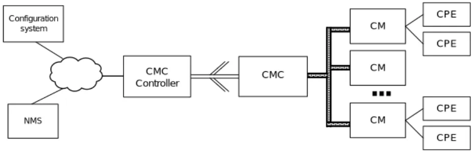
In this distributed system architecture, the CMC Controller manages the configuration of the CMC and/or forwards upstream and downstream service data. The CMC converts and forwards the upstream and downstream service data and the management and configuration data of the CMs. The CM terminates the upstream and downstream service data, as well as receiving and responding to management and configuration data. The CMC Controller connects to the CMC through a digital optical packet network. The CMC connects to the CMs through a coax RF network. The configuration system configures services and devices on the distributed system architecture. It generates and issues configuration files and upgrades the software of the CMs. The configuration system consists of the DHCP server, configuration file server, software downloading server, and time protocol server. The NMS consists of the SNMP management system and the Syslog server.
CM
...
Configuration system NMS CMC CMC Controller CM CM CPE CPE CPE CPEFigure 6-1 - C-DOCSIS System
6.2 Characteristics
This specification introduces several features based on a traditional DOCSIS system, as listed below:
• Distributed architecture for deep-fiber network: This specification introduces a three-level distributed
architecture including the CMC Controller, the CMC, and the CM. In a typical deployment, a CMC Controller bridges the digital optical distribution network and the convergence network, a CMC bridges the digital optical network and the coax network, CM bridges the terminal and CPE devices.
• Centralized network administration: This specification introduces a centralized network administration approach, defines the corresponding interfaces and protocols, and supports the end-to-end administration, provisioning, and monitoring of equipment and services.
• Modular equipment and system: This specification defines a series of new system modules. It supports different equipment modules, systems equipment, service requirements and features.
2
Added the name of another required spec per CDOCSIS-N-14.1216-2 on 2/9/15 by KR.
• CDT data plane interfaces: This specification defines a C-DOCSIS Data Tag (CDT) interface for service flow tagging among different modules, and provides a QoS guarantees for the system.
• CDMM interface: This specification defines a C-DOCSIS Management Message (CDMM) interface to support centralized administration requirement.
• Service flow convergence mapping: This specification defines a mapping protocol between DOCSIS service flows and VLAN tags to support QoS requirements and seamless connection with different type of networks.
• This specification applies to HFC networks featuring high-density residents, large number of users, various service types, and high QoS requirements.
• This specification has the advantages of simple networking operations, low product costs, and high management efficiency.
7 MODULES AND INTERFACES
7.1 Functional Modules
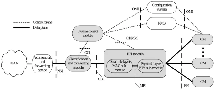
Figure 7-1 shows the functional modules of the distributed CMTS architecture.
CDMM CM
...
System control module Control plane Data plane CDT Aggregation and forwarding device CM CM MAN Classification and forwarding module RFI OMI NSI CCI NMS Configuration system OMI RFI module Data link-layer MAC sub-module Physical-layer PHY sub-module MPIFigure 7-1 - Functional modules of the distributed CMTS architecture
The C-DOCSIS system consists of a distributed CMTS and CMs. All references to a CMTS within this specification generally refer to a Distributed CMTS architecture. While the distributed CMTS consists of two physical devices – the CMC and CMC Controller – it can contains several logical modules. These distributed CMTS logical modules are: the system control module; the classification and forwarding module; and the RFI module (including the data link-layer MAC sub-module and the physical-layer PHY sub-module).
The distributed CMTS logical modules are defined as follows:
• System control module: This logical module is responsible for Configuration and management of the RFI module and the classification and forwarding module. For example, during CM registration, the system control module parses service flows and classification information reported by the CM and configures the classification and forwarding module accordingly. In addition, the system control module works with the NMS and the configuration system for service configuration and management.
• Classification and forwarding module: For downstream data flows, the classification and forwarding module matches data packets based on fields, such as those in the TCP, UDP, IP, as well as LLC headers (for example, MAC address, IP address, and TCP or UDP port number) of the data packets, and inserts into the data packet header the C-DOCSIS Data Tag of the service flow to which the data packet belongs. For upstream data flows, the classification and forwarding module inserts service identifiers of the aggregation network based on service mapping rules and forwards data to the network side.
• RFI module: This logical module implements the functions of the data link-layer MAC sub-module and the physical-layer PHY sub-module defined in this specification. In the downstream direction, the RFI module implements service flow-based scheduling, queuing, and shaping, creates DOCSIS MAC frames, as well as modulates and transmits RF signals. In the upstream direction, the RFI module receives RF signals, processes the DOCSIS MAC frame header, implements queuing and scheduling, and processes DOCSIS MAC
The configuration system and the NMS are the support systems in the distributed system architecture.
The configuration system configures services and devices in the distributed system architecture. It generates and issues configuration files and upgrades the software of the CMs. The configuration system consists of the DHCP server, configuration file server, software downloading server, and time protocol server. The DHCP server provides initial configurations including IP addresses for CMs and CPEs. The configuration file server provides configuration files for downloading when a CM is initialized. Configuration files are in binary format and contain the
configuration parameters of CMs. The software downloading server provides software images for downloading to upgrade CMs. The time protocol server provides correct time for time protocol clients, particularly for CMs. The NMS consists of the SNMP management system and the Syslog server. The SNMP management system configures and monitors CMC Controllers, CMCs, and CMs through SNMP. The Syslog server collects device operation messages. Other functions supported by the configuration system and the NMS are based on carriers' application requirements.
The distributed CMTS connects to a metropolitan area network (MAN) through an aggregation and forwarding device, which can be an optical line terminal (OLT), an Ethernet switch, or a router.
7.2 Interfaces on Functional Modules
7.2.1 Radio Frequency Interface (RFI)The RFI interface defines the interface specification at the data link and physical layers between the RFI module and the CMs, including:
1. Modulation modes and parameters for upstream and downstream channels 2. MAC layer characteristics
3. Electrical characteristics
For the application scenarios of the C-DOCSIS system, there are some changes compared with DOCSIS 3.0 in the requirements of RF interface, these are in the different aspects of the Physical layer, MAC layer, and electrical characteristics for downstream channels in an RFI interface.
7.2.2 Network Side Interface (NSI)
The NSI defines the physical interface and service flow mapping logic between the distributed CMTS and the aggregation network. The physical interface is not defined in this specification and can be a GE interface, a 10GE interface, an EPON interface, a GPON interface, or a 10G PON interface. The service flow mapping logic defines the mapping from service flows to Ethernet VLANs. For details, see Annex A.
When the distributed CMTS forwards data packets to the NSI and the CMTS does not implement routing, CMTS SHOULD carry the VLAN field in the data packets. If the CMTS does not implement routing, the CMTS MUST map the service flow sent to the NSI to a VLAN ID and the priority of the service flow to the VLAN priority, as defined in Annex A.
The CMTS MUST support the change of upstream IP priorities. The upper-layer aggregation device can schedule packets based on the VLAN or IP priority.
7.2.3 Operation and Management Interface (OMI)3
The operation and management interface (OMI) is used between the system control module and the NMS as well as the configuration system. It is also used between the CM and the NMS as well as the configuration system.
The NMS uses SNMP to configure, maintain, and monitor distributed CMTS components through the OMI and command line interface (CLI).
Through the OMI, the NMS configures, maintains, and monitors devices, and the configuration system provides service configuration. The policy server uses the Common Open Policy Service (COPS) protocol to communicate with the system control module through the OMI. The initial OMI requirements are defined in the [OSSIv3.0] Annex entitled "Additions and Modifications for Chinese Specification" and will be further defined in a separate OSSI specification.
7.2.4 C-DOCSIS Data Tag (CDT)
The CDT interface defines the identifier format on the data plane between the classification and forwarding module and the RFI module inside the distributed CMTS. The CDT interface uses the format of the 802.1p/q VLAN tag. The VLAN ID identifies the CM to which a data packet belongs, and the class of service (CoS) field identifies the service flow to which a data packet belongs. For details, see Section B.1 in Annex B. The CMTS distinguishes QoS properties of multiple services based on service flows.
In the downstream direction, the classification and forwarding module within the CMTS MUST classify data packets based on the classifier information defined in the configuration file or dynamic service flow signaling messages, and insert a CDT into the Ethernet frame header to identify the service flow. The RFI module within the CMTS MUST identify the service flow based on the CDT, and it shapes, schedules, and forwards traffic based on the QoS parameters defined in the configuration file or dynamic service flow signaling messages.
In the upstream direction, the CM classifies and shapes traffic. The CMTS monitors upstream traffic classification and traffic shaping. The RFI module within the CMTS MUST insert a CDT into the Ethernet frame header in the data packet to identify the service flow. The classification and forwarding module within the CMTS MUST be able to map the CDT to the service flag, such as S-VLAN, IP ToS, and Ethernet LLID, supported by the aggregation network to support the QoS policies used on the aggregation network.
7.2.5 C-DOCSIS Management Message (CDMM)
The CDMM interface defines the control messaging between the system control module and the RFI module as well as the message format. CDMMs are used to exchange configurations, status, and management information between the system control module and the RFI module. The configurations, status, and management information include channel and parameter configurations, transmit or receive status and statistics, load balancing, CM status, CM registration information, operations on dynamic service flows, as well as multicast and security information. For details, see Section B.2 in Annex B.
7.2.6 Control and Classifier Interface (CCI)
The CCI is the control interface between the system control module and the classification and forwarding module. In this specification these two modules are always built within the same device, either in a CMC device or a CMC controller. As such this specification does not define the message format for this interface. A CMC device or a CMC controller implementing the system control module is capable of configuring the classification and forwarding module based on the service flow information reported by the RFI module. In addition, a CMC device or a CMC controller is capable of obtaining protocol packets, such as DHCP packets and control point discovery (CPD) packets required for system control functions and sending these protocol packets to the system control module.
7.2.7 Main Path Interface (MPI)4
The MPI is the data communication and management interface between the data link-layer MAC sub-module and the physical-layer PHY sub-module of the RFI module. When the data link-layer MAC sub-module and the physical-layer PHY sub-module are implemented separately, the system uses the MPI protocol for their communications. The MPI protocol and format are implemented as defined in [MHAv2].
4
Modified per CDOCSIS-N-14.1216-2 on 2/9/15 by KR.
7.3 Data Packet Processing
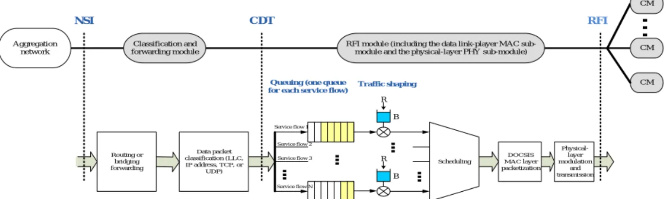
Figure 7-2 and Figure 7-3 show the data packet processing in the downstream and upstream directions, respectively, in a distributed CMTS architecture.
In the downstream direction, data packets are forwarded to the classification and forwarding module from the aggregation network side. The classification and forwarding module identifies which CM and service flow the data packet belongs to (according to provisioned or learned rules), inserts a CDT tag correspondingly, and forwards packets to the RFI module. The RFI module puts data packets into the queue associated with specific service flow, performs scheduling and rate shaping on queues, packetizes the data into DOCSIS MAC frames, and transmits the DOCSIS MAC frames via RF.
Service flow 1 Service flow 2 Data packet classification (LLC, IP address, TCP, or UDP) Service flow 3 Service flow N
...
R B Traffic shaping Queuing (one queuefor each service flow)
Scheduling
...
R B...
...
Routing or bridging forwarding DOCSIS MAC layer packetization Physical-layer modulation and transmission CM...
RFI module (including the data link-player MAC sub-module and the physical-layer PHY sub-sub-module) Aggregation network CM CM Classification and forwarding module NSI CDT RFI
Figure 7-2 - Processing downstream data packets in the distributed CMTS architecture
In the upstream direction, data packets are forwarded to the CM from the home network. The CM classifies ingress data packets according to provisioned classification rules, performs queuing and rate shaping according to
provisioned QoS parameters, then forwards packets to the RFI. The RFI module schedules upstream service flow transmissions according to the provisioned scheduling type, receives packets from the service flows, inserts a CDT tag as appropriate, and then forwards packets to the classification and forwarding module. The classification and forwarding module inserts service identifiers of the aggregation network based on provisioned service mapping rules (Section 8.1) and forwards packets to the aggregation network side.
SF 1 SF 2 Classifier (Ethernet, IP, UDP/ TCP fields) SF 3 SF N ... R B Shape Queue Schedule ... R B ... ... Home network to WAN bridging and routing DOCSIS MAC DOCSIS PHY and RF RFI module Aggregation and forwarding equipment CM Classification and forwarding module NSI CDT RFI DOCSIS MAC DOCSIS PHY and RF ToS overwrite; Service-VLAN mapping Scheduler DOCSIS Requests from CMs DOCSIS MAPs To Downstream DOCSIS MAPs from downstream Bridging and/or routing Home Network MAC
headers (one queue per Service Flow)
Transmit
8 SYSTEM REQUIREMENTS AND DEVICES
8.1 System Requirements
In the system implementation shown in Figure 7-1, the C-DOCSIS system can be the C-DOCSIS I, II, or III system according to different module combinations defined in Section 7. As previously defined, the distributed CMTS consists of a CMC and a CMC Controller. The requirements for CMCs and CMC Controllers are defined in this section.
The CMTSs (consisting of CMCs and CMC Controllers) MUST comply with the data forwarding, QoS, and security requirements defined in this section.
8.1.1 Data Forwarding Requirements 1. Basic Forwarding Requirements
The CMTS MUST support bridging or routing forwarding. The CMTS MUST support mapping from service flows to VLAN IDs if only bridging forwarding is required. For details about the mapping mode, see Annex A. 2. Multicast
The CMTS MUST support the IGMPv2 [RFC 2236] and MLDv1 [RFC 2710] multicast protocols. The CMTS MAY support the IGMPv3 [RFC 3376] and MLDv2 [RFC 3810] multicast protocols.
The CMTS MUST support IGMP or MLD snooping if it's a bridging CMTS. The CMTS MAY support IGMP or MLD proxy.
The CMTS MAY support multicast join authentication specified in [MULPIv3.0]. 3. DHCP Relay Function
On a DOCSIS access network, the CMs, CPEs, and configuration system can be on different physical network segments. In this case, the CMs and CPEs as DHCP clients cannot directly send DHCP broadcast packets to the DHCP server but they can be converted to unicast packets by the DHCP relay function and sent to the DHCP server. The CMTS MUST support DHCP relay. The specific requirements for DHCP relay are as follows: a) The devices that are supported by DHCP relay can be CMs, STBs, eMTAs, and other computational
devices.
b) Multiple DHCP servers can be configured for the CMTS.
c) The CMTS MUST be capable of identifying DHCP Option 60 and DHCP Option 43, and selecting the DHCP server and the IP address of the relay proxy based on the value of these two options.
d) The CMTS MUST support the insertion of DHCP Option 82. DHCP Option 82 is defined as follows: 1) 82.1 Circuit ID: Information about the interface that receives DHCP request messages 2) 82.2 Remote ID: MAC address of the CM sending DHCP messages
3) 82.9 DHCPv4 Vendor-Specific Information relay agent sub-option [CANN DHCP] Among the above three items, only 82.2 Remote ID is mandatory.
DHCP Option 60 contains a string that describes capabilities of the DHCPv4 client. [CANN DHCP] describes the values of DHCP Option 60. Some of the values are described below as a reference in Table 8–1.
Table 8–1 - Values of DHCP option 60
Device String in DHCP Option 60 Description
CM String beginning with "docsis" The subsequent string describes the DOCSIS version and capability supported by the CM. See [CANN DHCP] for details.
The CM can be an independent CM or an embedded CM, such as the CM embedded to an STB.
eMTA String beginning with "pktc" The subsequent string can describe the DOCSIS version and capability supported by the eMTA. See [CANN DHCP] for details.
CMC String beginning with "cmc" The subsequent string can describe the DOCSIS version and capability supported by the CMC. See [CANN DHCP] for details.
The CMC can be a CMC I device, CMC II device or CMC III device.
The definition of DHCPv4 Option 43 and Option 60 needs to comply with [CANN DHCP].
The CMTS MAY support DHCPv6. The CM complies with the DHCPv6 fields defined in [CANN DHCP]. The CMTS MAY support other DHCP relay requirements defined in [MULPIv3.0].
8.1.2 QoS Requirements
The CMTS MUST support DOCSIS 3.0-compliant service flow classification, scheduling, and QoS parameters as defined in [MULPIv3.0]. The CMTS MUST support at least 1024 upstream and downstream service flows. The CMTS MUST support overwriting of IP priorities for upstream and downstream data packets according to the TLV parameter defined in [MULPIv3.0], and support the reconfiguration of the IP priorities of the data packets received on the RFI and NSI. In addition, the CMTS MUST support the mapping of DOCSIS service priorities to [802.1Q] priorities when they forward data upstream in bridging mode. For details about the mapping of service flows on NSI, see Annex A.
The CMTS MAY support the dynamic configuration of QoS policies, which can be implemented according to either PacketCable Dynamic QoS [DQoS] or PacketCable Multimedia [MM]. The dynamic configuration of QoS policies allows the CMTS to dynamically create, modify, or delete a service flow to ensure the QoS for multimedia sessions, such as voice sessions. With this mechanism, the system provides guaranteed bandwidth resources during a session and releases the resources when the session ends. A dynamic service flow can be initiated from a CMTS or a CM. For detailed information, see Appendix I.
8.1.3 Security Requirements
The CMTS MUST support security requirements defined in the Annex titled "Additions and Modifications for Chinese Specification" in [SECv3.0].
8.1.4 Operations Support Requirements5
The CMTS MUST support operations support as defined in the Annex titled "Additions and Modifications for Chinese Specification" in [OSSIv3.0].
8.2 C-DOCSIS I System and Devices
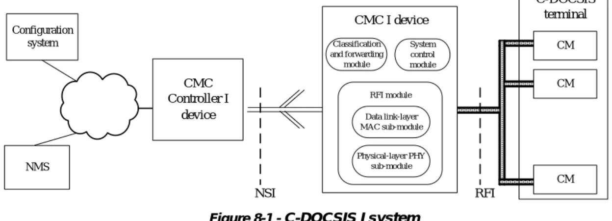
The C-DOCSIS I system consists of the CMC Controller I device, CMC I devices, and CMs. The CMC Controller I device works with the CMC I devices to implement CMTS functions.
In this architecture, the CMC I device contains the classification and forwarding module, the RFI module, which includes the data link layer MAC sub-module and the physical layer PHY sub-module, and the system control
module. The CMC I device classifies and forwards service data, implements data link layer MAC framing, as well as data modulation and demodulation on the physical layer. The CMC I device is deployed closer to the user side on the network, typically at the fiber node. CMs implement the functions of the CM module specified in Section 7.1. In the C-DOCSIS I system, the system control module of the CMC I device controls protocols, configurations, and managements of services. The CMC Controller I device implements service aggregation and routing.
The CMC I device communicates with CMs through the RFI specified in Section 7.2.1 to implement HFC network communication. The CMC I device connects to aggregation networks through the NSI specified in Section 7.2.2 to forward data flows and map services defined in this specification. The CMC I device communicates with the configuration system and the NMS through the OMI interface specified in Section 7.2.3 over IP channels provided by the aggregation network to configure services and manage the network. The CMC I device communicates with the policy server to perform operations on dynamic service flows.
CM CM CM
...
Configuration system NMS C-DOCSIS terminal CMC Controller I device CMC I device System control module Classification and forwarding module Data link-layer MAC sub-module Physical-layer PHY sub-module RFI module NSI RFIFigure 8-1 - C-DOCSIS I system
In a system implementation, the CMC Controller I device can be either a separate device or a component embedded in an aggregation and switching device, such as a router, a switch, or an OLT. Because the CMC I device contains a classification and forwarding module, a system control module, as well as an RFI module, the data forwarding and QoS functions defined in Section 8.1 SHOULD be implemented on the CMC I device.
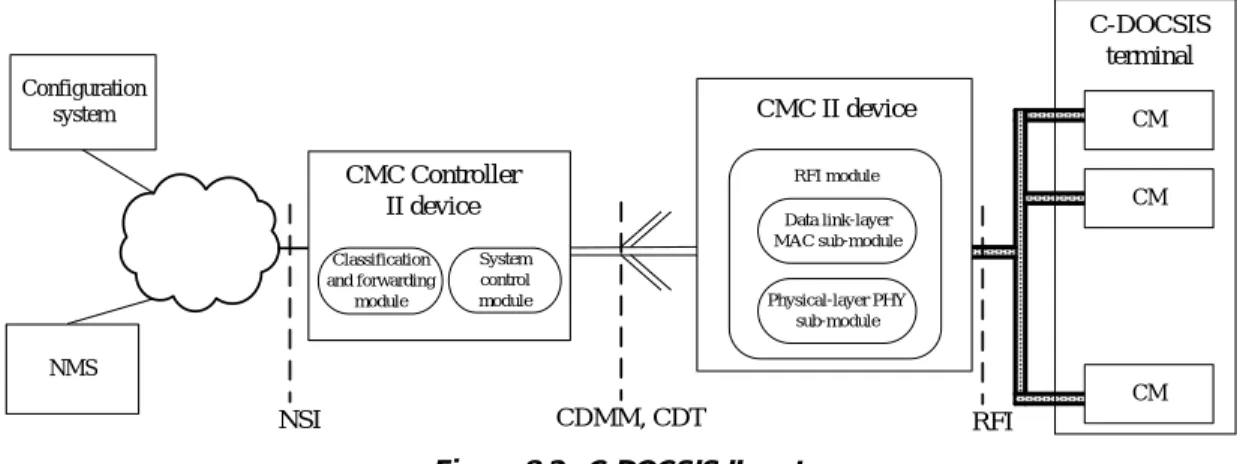
8.3 C-DOCSIS II System and Devices
6The C-DOCSIS II system consists of the CMC Controller II device, CMC II devices, and CMs. The CMC Controller II device works with the CMC II devices to implement CMTS functions.
In this architecture, the CMC Controller II device contains the classification and forwarding module and the system control module to implement the following functions: service flow classification and forwarding, configuration and management of CMC II devices, and configuration and control of services. The CMC Controller II device is deployed at the hub site. The CMC II device contains the RFI module (refer to Section 7.1), including the data link-layer MAC sub-module and the physical-link-layer PHY sub-module, to implement the data link-link-layer MAC framing as well as data modulation and demodulation on the physical layer. The device is deployed close to the user side on the network. CMs implement the functions of the CM module specified in Section 7.1.
The CMC II devices and the CMC Controller II device use the CDT specified in Section 7.2.4 and the CDMM specified in Section 7.2.5 to mark service flows and to control and manage services. The CMC II device communicates with CMs through the RFI interface specified in Section 7.2.1 to implement HFC network
communication. The CMC Controller II device connects to the aggregation networks through the NSI specified in Section 7.2.2 to forward data flows and map services defined in this specification. The CMC Controller II device communicates with the configuration system and the NMS through the OMI interface specified in Section 7.2.3 over
6
Modified per CDOCSIS-N-14.1216-2 on 2/9/15 by KR.
IP channels provided by the aggregation network to configure services and manage the network. The CMC Controller II device communicates with the policy server to perform operations on dynamic service flows.
CM CM CM
...
Configuration system NMS C-DOCSIS terminal CMC II device System control module Classification and forwarding module CMC Controller II device Data link-layer MAC sub-module Physical-layer PHY sub-module RFI module NSI CDMM, CDT RFIFigure 8-2 - C-DOCSIS II system
In a system implementation, the CMC Controller II device can be either a separate device or a component integrated in an aggregation and switching device, such as a router, a switch, or an OLT. The CMC Controller II device contains classification and forwarding modules and the system control module, and the bridging or routing forwarding function. The CMC Controller II device SHOULD implement the service-flow-to-VLAN mapping function, the multicast control function, the DHCP relay function, the service flow classification function, and the IP priority overwriting function defined in Section 8.1. The CMC II device SHOULD implement the service flow scheduling and the queuing and rate shaping functions.
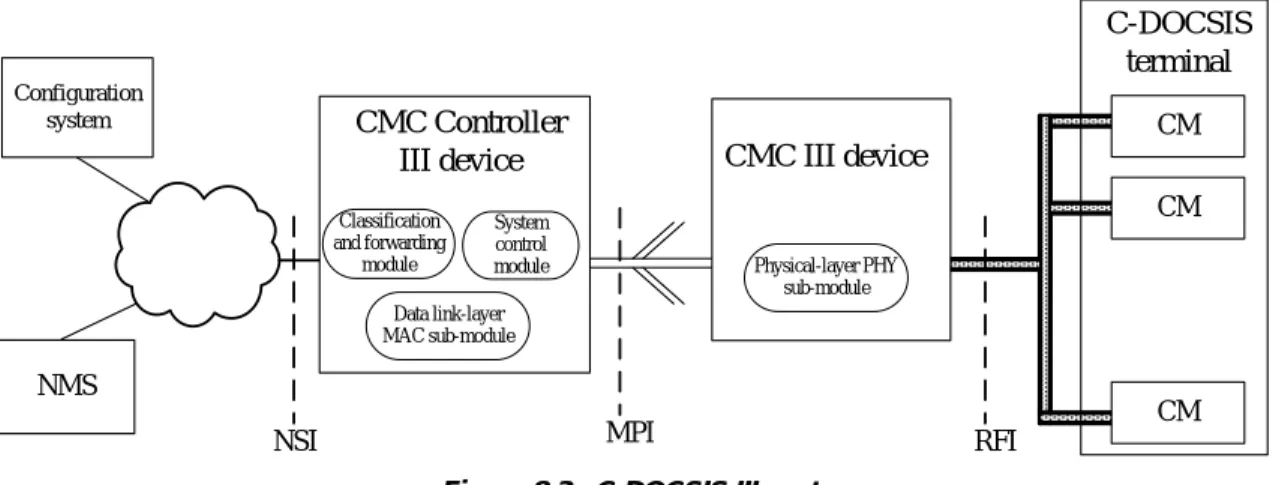
8.4 C-DOCSIS III System and Devices
7The C-DOCSIS III system consists of the CMC Controller III device, CMC III devices, and CMs. The CMC Controller III device works with the CMC III devices to implement CMTS functions.
In this architecture, the CMC Controller III device contains the classification and forwarding module, the data link-layer MAC sub-module, and the system control module to implement the following functions: classify and forward service data, implement data link-layer MAC framing, control system protocols, configure and manage services, and manage the system and devices. The CMC Controller III device is deployed at the hub site. The CMC III device contains the physical-layer PHY sub-module to modulate data and change frequencies at the physical layer for service data. The device is deployed closer to the user side on the network, typically at the fiber node.
The CMC III device communicates with CMs through the RFI interface specified in Section 7.2.1 to implement HFC network communication. The CMC Controller III device communicates with the configuration system and the NMS through the OMI interface specified in Section 7.2.3 over IP channels provided by the aggregation network to configure services and manage the network. The CMC Controller III device communicates with the policy server to perform operations on dynamic service flows. The data link-layer MAC sub-module and the physical-layer PHY sub-module of the RFI module implement data communication and management through the MPI interface specified in Section 7.2.7.
CM CM CM
...
Configuration system NMS C-DOCSIS terminal CMC III device System control module Classification and forwarding module CMC Controller III device Data link-layer MAC sub-module Physical-layer PHY sub-moduleNSI MPI RFI
Figure 8-3 - C-DOCSIS III system
In this system, the CMC Controller III device can be either a separate device or a device supporting core CMTS functions, such as a CMTS, router, or switch. Accordingly, the physical channel between the CMC Controller III device and the CMC III devices can be an optical PON network or a GE Ethernet network. The CMC Controller III device manages all CMC III devices, CMs, and CPEs in a unified manner. It supports real-time detection of and responds to events such as a CMC III device going online or offline.
The CMC III Controller uses the MPI described in Section 7.2.7, which includes a Generic Control Plane (GCP) to manage CMC III devices, an Upstream External PHY Interface (UEPI), and a Downstream External PHY Interface (DEPI) to transmit data traffic between the CMC III controller and CMC III devices. GCP is based on TCP/UDP and can take over all network management for CMC III devices. UEPI and DEPI are based on the L2TPv3 protocol; it can pass through any L2 and L3 network. The C-DOCSIS III system architecture is described in a separate set of specifications known as Modular Headend Architecture v2 [MHAv2].
Because the CMC Controller III device contains a classification and forwarding module, the system control module, as well as a data link-layer MAC sub-module, it SHOULD implement the data forwarding and QoS functions defined in Section 8.1. The VLAN mapping defined in Section 8.1 is not required for the C-DOCSIS III system.
Annex A Service Flow Mapping to VLAN
The Service flow to VLAN mapping is implemented on the NSI. If the CMTS does not implement routing, it MUST support mapping from service flows to VLANs.
The classification and forwarding module in the CMTS MUST support the mapping from upstream service flows to VLAN IDs. The mapping from upstream service flow references or service class names to VLAN IDs can be configured. This configuration is global. That is, all the service flows with the same service flow reference or service class name are mapped to the same VLAN ID.
The classification and forwarding module in the CMTS MUST support the mapping from priorities of upstream service flows to [802.1Q] priorities. The mapping from the priorities defined by the upstream traffic priority or service class to [802.1Q] priorities can be configured. This configuration is global. That is, all the upstream service flows with the same traffic priority or service class name are mapped to the same [802.1Q] priority.
The classification and forwarding module in the CMTS MUST support the mapping from all dynamically created service flows to the same VLAN ID or [802.1Q] priority, or enable users to configure the mapping from service class names to VLAN IDs and [802.1Q] priorities.
• Examples of mapping DOCSIS services to VLANs: Assume that video, Internet access, and voice services are available and their upstream service flow references are SFrA, SFrB, and SFrC respectively. These three types of services can be mapped to different VLAN IDs, for example:
− SFrA -> VLAN 1 − SFrB -> VLAN 2 − SFrC -> VLAN 3
• These three types of services can also be mapped to the same VLAN ID, for example: − SFrA -> VLAN 4
− SFrB -> VLAN 4 − SFrC -> VLAN 4
In addition, one type of service can have different upstream service flow references. For example, video services support SFrD and SFrE in addition to SFrA. These upstream service flow references are mapped to the same VLAN; that is, different users can use different upstream service flow references to identify the same service.
During priority mapping, the priority defined in the upstream traffic priority or service class is used directly as [802.1Q] priority.
In the downstream direction, the classification and forwarding module in CMTS strips off VLAN tags and adopts packet classification rules for service flows classification and QoS scheduling.
Service flow to VLAN mapping MUST be implemented on a CMC in C-DOCSIS I system, and implemented on CMC Controller in a C-DOCSIS II system and a C-DOCSIS III system.
Annex B CDMM and CDT
B.1
C-DOCSIS Tagging (CDT)
The C-DOCSIS data tag (CDT) format is a method of using VLAN tags to indicate the Service Flow to which a packet has been classified. It is used in the data plane to identify Service Flows on the link between the classification and forwarding module and the RFI module.
For downstream data traffic, the classification and forwarding module in the CMTS MUST add a CDT-formatted VLAN tag to each packet that is classified to a unicast Service Flow, indicating to which Service Flow the packet was classified. Other VLAN tags may be present, but CMTS MUST ensure that the CDT-formatted VLAN tag is in the outermost position when the packet reaches the RFI module in the CMTS.
In the upstream direction, the RFI module in the CMTS MUST add a CDT-formatted VLAN tag to each data packet that is forwarded from a cable modem, indicating on which Service Flow the packet was received. If other VLAN tags are present, the CDT tag MUST be in the outermost position at the point where the packet leaves the RFI module in the CMTS.
The format of the CDT VLAN tag is illustrated in Figure B–1.
0x88A8 Service 0 1 0 0 CM Index
0 8
11 13
15
TPID CoS VID
31
CFI
Figure B–1 - CDT VLAN Tag Format
The fields are as follows:
• TPID: The value 0x88A8 is defined by [802.1Q] as the TPID value for a Service Provider (S-VLAN) tag, which is the outer tag in a double-tagged packet.
• CoS/PCP bits: In [802.1Q], this field is defined as a Priority Code Point (PCP) and used to indicate the packet priority as specified by [802.1Q]. However, the RFI module does NOT use this field to indicate priority. The RFI module uses this field only as an identifier. In conjunction with the VID, this field identifies the Service Flow to which the packet belongs. The contents of the CoS/PCP field have no impact on the QoS treatment of the flow by the RFI module. The RFI module determines the priority and other QoS parameters of the flow based on the DOCSIS TLV encodings specified in the DOCSIS messages used to set up the flow.
• CFI bit: This bit is always set to zero for CDT.
• VID: The system control module in the CMTS MUST choose a VID value between 0x801 and 0x9D0. The lower 9 bits of this value are the "CM Index" and are always the same for Service Flows to or from the same cable modem.
The combination of VID and CoS bits identifies the Service Flow to which the packet has been classified. Each VID+CoS value corresponds to a single Service Flow in a given direction. The values of VID and CoS that
correspond to a Service Flow are selected by the system control module at the time the flow is admitted or activated. The system control module always chooses the same VID for Service Flows to or from the same CM. Different values of CoS bits identify different flows to or from the CM. A particular value of CoS bits may be used once for a downstream flow and once for an upstream flow to/from the same CM. Since there are eight possible values for the CoS bits, a single VID can be used for up to eight downstream flows and up to eight upstream flows.
At the RFI module, in the downstream direction, all packets with a given VID+CoS combination in the CDT tag will be placed in a single queue in the order received. The RFI module then schedules the queue based on the DOCSIS QoS parameters for the corresponding Service Flow. The actual value of the CoS field is not important to the RFI module, and does not affect the priority of the Service Flow. The system control module MAY choose any value for the CoS bits for any flow without affecting the priority of the flow.