Real-time long-distance pre-visualisation with live
keying using commodity hardware: compositing in
the cloud
Paul Melis1, Meindert Kok2, Harry Schreurs2, Erik Ruiter3, Paul Wielinga4, and Tijs de Kler1
1Visualization Group, SURFsara, {paul.melis,tijs.dekler}@surfsara.nl 2Netherlands Film Academy, Amsterdam School of the Arts,
{meindert.kok,harry.schreurs}@ahk.nl
3Network Innovation and Support Group, SURFsara, [email protected]
October 8, 2013
Abstract
We describe a technical demonstration shown at the Cinegrid Interna-tional Workshop 2012 in which live film footage of an actress in front a green screen and a few physical elements was combined with a virtual set in real time, using a distributed processing pipeline that connected two locations on different continents: a director located in San Diego that di-rected the filming of a few scenes being filmed in a studio in Amsterdam, with final output being shown in San Diego.
The approach described combines pre-visualisation, real-time keying and rendering, distributed processing using optical networks to enable a creative process between geographically separate locations.
1
Introduction
In the visual effects (VFX) industry a lot of 3D work is being outsourced to different companies all over the world, while the actual film shoot takes place in another country. Secondly, more and more creative tools are being used to start building the scripted story in 3D in a very early stage: pre-visualization and animatics become an important part of the pre-production process for a movie or the VFX produced for it.
Here we describe a technical demonstration performed at the Cinegrid In-ternational Workshop 2012 in December 2012 at the California Institute for
Telecommunications and Information Technology (Calit2) at the University of California, San Diego. The purpose of the demonstration was to show that doing pre-visualization is possible in a distributed manner, as well as showing the possibilities of working between geographically separated locations.
In this demonstration we wanted to give a director the possibility to work with real actors in front of a greenscreen combined with a virtual set in real-time during rehearsals, before the actual film shoot, just to give him/her a general idea how the total scene would look and, if necessary, make adjustments and/or improvements.
A second goal was to build a demonstration setup (in the form of a physical and virtual set and tracked camera) which could be reused for student exercises. By letting film students (prospective directors, camera (wo)men, etc.) work in such a setup they could experience how to work with real-time virtual environ-ments, could learn how to use these virtual environments for the interactive pre-production process of film making, and in general could prepare themselves for their future work in the global VFX industry.
A (technical) reason for wanting to create a distributed processing pipeline is that with higher image resolutions, like Ultra-HD/4K [16] or even Super Hi-Vision/8K, becoming accepted standards and being increasingly used in film production the need arises for high-performance processing in case real-time composited output (or approximation thereof) is required, as is the case here. A scalable approach using distributed processing over multiple processing/render nodes coupled by dedicated high-bandwidth low-latency optical networks makes real-time output more attainable compared to using a single central processing system. Where the processing power is located becomes therefore less impor-tant, as long as connectivity requirements are met, and fits the trend these days of moving towards cloud-based computing.
2
Overview
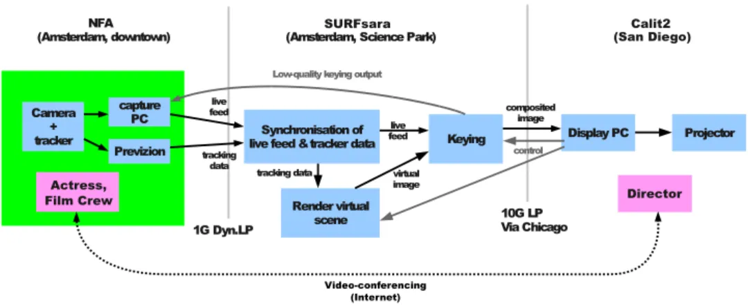
Three locations were involved in the demonstration, the first two in Amsterdam: 1) a film studio at the NFA and 2) the Collaboratorium at SURFsara were a render node performing rendering of a virtual set and image compositing was located. The third location was the VRoom at Calit2 [6] in San Diego, where the final composited footage was shown and a presenter took the role of director to direct the filming in the studio in Amsterdam.
The live images shot in front of the greenscreen in the film studio were captured and sent over a light path to a render node at SURFsara, together with associated camera tracking data. There, a virtual 3D scene was rendered based on the tracking data and composited together with the live footage to produce the final output, which was then sent out to Calit2, over a second light path. A mirror feed of the final output was sent back to the NFA studio, but used lossy image compression and a lower framerate, in order not to degrade the packet
NFA
(Amsterdam, downtown) (Amsterdam, Science Park)
Camera + tracker capture PC Previzion Synchronisation of
live feed &tracker data Keying Display PC Projector
Render virtual scene
1G Dyn.LP 10G LPVia Chicago
live feed
tracking
data tracking data
live feed virtual image composited image control Low-quality keying output
SURFsara
(San Diego)Calit2
Director Actress,
Film Crew
Video-conferencing (Internet)
Figure 1: High-level overview of demonstration setup
stream containing the live video feed being sent over the same connection. The major parts of the system involved (see Figure 1) were:
• Camera tracking and capture at the NFA studio
• Synchronisation of the incoming live video and tracking data based on timecodes
• Rendering of the virtual 3D scene based on the camera tracking data
• Performing keying, combining the live and virtual imagery and sending out the result over the network
• Displaying the final output received over the network We now discuss the elements of the setup in more detail.
2.1 Greenscreen studio at NFA
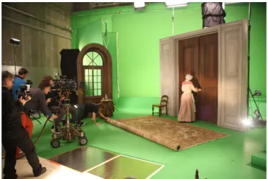
The film studio at the NFA measured 14x20 meters and was decorated with greenscreen backgrounds and a painted green floor. The set contained a few physical elements providing a context in which the actress could act. See Fig-ure 2. The physical elements in the scene were precisely lined up with cor-responding cutouts in the virtual 3D model, for a seamless blend of real and virtual elements, using a physical reference point. The virtual scene used was much bigger than the physical set to provide for some nice camera shots (see 4). A professional actress was hired to portray a housekeeper in the demonstra-tion scenes and all lighting and camera work was performed by a professional crew. A small audience was present during the demonstration.
Figure 2: Schematic of studio space and set used at the NFA, showing green-screen setup, physical elements and reference point R. Also note the three steps of (physical) staircase.
2.2 Camera tracking and capture
One of the parties involved in the demonstration described, the Dutch Film Academy (NFA), owns a PreVizionR Portable set, a product by Lightcraft
Technology [8]. This is a commercial solution for performing real-time key-ing, trackkey-ing, renderkey-ing, compositing (and more) for use in film and television production. It is limited (in the version used here) in resolution to 1920x1200 pixels and, being a commercial proprietary system, can’t easily be extended or modified for experimental purposes without voiding the warranty. Furthermore, it performs all processing on a single machine, which might become a processing bottleneck for high-resolution images.
The camera used was a Sony PMW-F3 with a RED 18-85mm zoom lens. Live footage was shot in 1080p resolution at 23.975 frames per second and video output was sent over an HD-SDI connection to a Lightcraft PreVizion unit. The PreVizion provided the real-time camera tracking. PreVizion uses a combination of optical and inertial tracking. For optical tracking the studio ceiling was decorated with 70 fiducial markers, see Figure 3.
The tracking data used was 1) camera position, 2) camera orientation and 3) lens field of view1. The real-time tracking data is made available by the PreVizion unit on a TCP network port. It sends out the necessary values each frame in an XML-based format.
Live footage was captured using a dedicated capture PC with BlackMagic DeckLink SDI capture card [1]. The capture format was 8-bit YUYV 4:2:2,
1
Figure 3: Fiducial markers on the studio ceiling
which (at 795 Mbit/s) nicely fits over a 1 Gbit/s link.
The synchronisation of live video and tracking data used a timecode-based method (described in the next section). A recent update to the PreVizion system allows embedding tracking data in the HD-SDI signal of the live video, but this feature wasn’t used, as it requires capturing at 10-bit per channel in order to extract the tracking metadata (which is stored in ancillary frame lines). At this higher channel resolution the captured video signal would no longer fit over the 1G link from the NFA to SURFsara. Instead, we opted for feeding the live video into the PreVizion system, which added a timecode and provided the augmented signal on an output HD-SDI connection. The capture PC received the augmented signal2.
2.3 Synchronisation of live video and tracking data
As mentioned in the previous section the live video was sent to the render node at SURFsara using a UDP packet stream, were complete frames were re-assembled and packet loss handled. The real-time camera tracking data was read off the PreVizion unit over a TCP connection. The full live video frames and tracking data were received independently, so a synchronisation step was needed to match up corresponding pairs of data based on (SMPTE) timecodes. The process performing this worked fairly straightforward. It waited until it had received at least one live frame and one set of camera tracking data, dropping incoming data if only a single data stream was received and its queue almost full. The oldest received data pairs were then compared on timecode value and, if they didn’t match, resulted in dropping the oldest piece of data. This process repeated until a matching live frame and tracking data pair had been received. At this point the synchronisation process sent tracking data off to the 3D renderer described in the next section, waited for completion of the rendering and then forwarded the live, virtual and garbage frame data to the
2I.e., Figure 1 is slightly incorrect, in that the live video didn’t go directly to the capture
keyer for compositing (described in section 2.5).
2.4 Rendering
The software used for rendering the virtual scene based on the camera tracking data was the open-source game engine OGRE [2]. The render node used was an 8-core Linux node with Intel Xeon E5630 processor, 24 Gbyte RAM, two NVidia Geforce GTX560 graphics card and 10 Gbit/s Intel NIC. Rendering of the virtual scene in OGRE was done on only one of the GPUs.
The OGRE engine was used as an on-demand render process, were it received camera data for the current viewpoint, orientation and field of view to render over a TCP connection. It then performed two frame renders to produce the corresponding rendered virtual scene and garbage matte images. Two offscreen render targets were used, the first an 8-bit RGBA target used for storing the rendered virtual scene. The second used 8-bit luminance (greyscale) for storing the rendered garbage matte view. The image data read back from the render targets was sent in unaltered form over the TCP connection as response, with only a small header preceding the data.
The virtual 3D scene was modeled in Modo, then exported to FBX for-mat [5], so it could be loaded in the PreVizion system. The latter provided a live view of the keyed scene on a viewfinder mounted on the camera, for the camera operator to work with. The FBX scene was converted to an OGRE model using Maya and the OgreMax converter [3], so it could be loaded in the realtime rendering process.
2.5 Compositing
An initial proof-of-concept implementation of almost the complete processing pipeline used UltraGrid [14] for capturing frames, performing real-time com-pression to DXT1 format [11] and receiving and displaying final output. Using the lossy DXT1 compression format for video results in very low bandwidth re-quirements, making it possible to send even 4K frames at 23.975 FPS over a 1 Gbit/s link. The compositing step in this pipeline operated on the level of Ultra-Grid RTP-based packets ([13], [10]): an 8x8 block of DXT1-compressed pixels was uncompressed to RGB, keyed with the corresponding block of live video, recompressed to DXT1 and finally stored back in the packet, overwriting the original image payload. The altered RTP packet was then forwarded to the final destination with its original RTP and UltraGrid headers still intact. This simple method worked quite well and was used for a first demonstration in Septem-ber 2012 at the Cinegrid Amsterdam event “De toekomst met 4k”. However, this pipeline was performing all compositing computations on the CPU (includ-ing DXT1 decompression), it neglected to handle RTP auxillary data normally transmitted using RTCP and wasn’t very modular. It also lacked handling of garbage mattes and switching between different output types.
Subsequently, the pipeline was reworked. Frame capturing still used a packet-based protocol to transmit captured frames, but the UltraGrid packet format was replaced by a simpler format that stored one or more complete image scanlines per packet, using UDP as the transport protocol. The image processing steps were changed to no longer work on invididual packets, but on full image frames. The first step in the packet receive process was changed to first reassemble a complete frame (handling any packet loss). Full frames where then processed and exchanged between processing steps using regular TCP connections (which used the Linux loopback interface, as all processing ran on the same machine3). The resulting image output was then sent out in UDP packets to the final destination in San Diego.
The keying step was implemented in a GLSL shader and used the second GPU in the render node4. Input image data was uploaded to the GPU in several OpenGL textures: one for each of live video, virtual scene and garbage matte. The garbage matte was used to mask out parts of the physical studio where no greenscreen was visible in the live footage. A second temporary garbage matte was used to obscure the actress as she walked down the stairs behind a virtual wall. This temporary matte was switched on and off by hand during the demonstration. The latter is not something that is done often in production, but served as a nice demonstration of the usage of mattes and the interactivity of the whole pipeline.
The keying algorithm used by no means produced production-quality output, such as provided by the PreVizion unit or offline production tools. However, it was felt that the keying itself wasn’t the most important part of the demonstra-tion and the quality was acceptable.
The compositing output used 8-bit RGBA format (resulting in 1.6 Gbit/s of bandwidth used). The alpha channel wasn’t strictly necessary, but the com-positing output needed to be read back from GPU memory and in general using a 4-byte pixel format allows higher pixel readback bandwidth than using a 3-byte format, due to the way the internal GPU memory is layed out, see [7].
A small GUI application was created to be able to switch between different types of ouput to be sent out from the render node. Besides the keyed results the director could request as output the raw live video filmed in Amsterdam, the rendered virtual scene, a wireframe overlay of the virtual scene over the raw live video and the grayscale garbage matte image.
2.6 Network
As this demonstration involved three different locations network connections with low latency and sufficient bandwidth were required. Two dedicated light paths were used. The first was a dynamic light path of 1 Gbit/s between the
3But allows the possibility of distributing processing steps over multiple nodes connected
using TCP
NFA and SURFsara, i.e. local within Amsterdam. The second light path was a 10 Gbit/s link between SURFsara and Calit2, utilizing NetherLight [9] and CAVEwave.
Regular H.323-based video-conferencing sets were used to communicate (over the public Internet) during the demonstration between the director in San Diego and the film studio in Amsterdam.
3
Results
The demonstration of the system described went smoothly and three small film scenes were successfully directed, acted out, filmed and the composited output shown in San Diego for an audience (see also Appendix A). Total end-to-end latency of the processing pipeline was not measured, but was at least 340ms. This is due to the fact that the synchronisation process received the captured live video around 6 frames later than the corresponding tracking data, forcing it to wait for 6*1000/23.975 = 250ms to pair up the two. One-way network latency from SURFsara to Calit2 was about 90ms (based on a 180ms “ping” round-trip time). The latency on the connection between the NFA and SURFsara was negligible at 0.1ms. Latency between changing output type in San Diego using the control GUI and subsequent change in output image was estimated to be less than a second5.
Even though the pipeline latency was obviously not negligible in this setup the perceived latency was much less than anticipated and proved no issue in the artistic process involving the director in San Diego and actress and crew in Amsterdam. The whole process was as interactive as it would normally be, except for some occasional miscommunication due to the use of video-conferencing instead of direct face-to-face contact.
A making-of style documentary and video registration of the actual demon-stration can be found in [15] and [12], respectively.
4
Conclusions
The described system performed well during the demonstration and shows what is possible with today’s commodity hardware and fast inter-continental light paths. The focus here was on pre-visualisation and interactivity between the parties involved, not producing a production-quality system. The fact that commodity hardware could be used for rendering and keying shows the process-ing power that modern CPUs and GPUs, coupled with optical networks, can provide.
Being performed within the scope of the Cinegrid Amsterdam project [4] one of the early goals for this demonstration was to film in and perform processing on
images in 4K resolution. So we initially looked for a 4K camera that provided live video output, as that was a necessity for a real-time demonstration. However, at the time of the project there was a very limited choice in 4K cameras with live output. The only available camera we could obtain (a JVC GY-HMQ10) lacked the required PL lens mount. This type of mount was required in order to track lens information for correct matching of live and virtual imagery. This forced us to lower the filming and processing resolution to 1080p instead, also due to time constraints. We still think 4K resolution is attainable with the current system, by scaling up the processes involved and parallelizing them were needed (e.g. if keying in 4K proves to be unattainable with a single GPU). Obviously, bandwidths for some of the network connections may need to be increased, but the software framework itself should be a good basis for a high-resolution version.
In retrospect, OGRE might not have been the best choice, due to the lack of usable tools to work with, convert and view scenes in the custom file format that OGRE uses. But a few considerations at the time had to be made in choosing the rendering software to use: 1) the software had to be usable on Linux (as the render node used was a Linux system), 2) there should be an exporter available for Maya and, most importantly, 3) it should provide a way to read back rendered frames with a high enough framerate. The wish to use an open-source package also limited the choice. Although OGRE satisfied 1) and 3), the maturity of available the tool set was disappointing. Were we to replace OGRE alternative choices could be OpenSceneGraph, Panda3D or Unity (the latter didn’t come in a Linux version at the start of this project).
Acknowledgements
Thanks to Laurin Herr and Natalie van Osdol of the Cinegrid International Workshop program committee and Todd Margolis and Joe Keefe of Calit2 for making the demonstration possible and providing (technical) support during preparation.
Special thanks to SURFnet for providing a last-minute upgrade to enable jumbo frames on the 1G lightpath from the NFA to SURFsara.
This work was funded by the European Fund for Regional Development (EFRO), Pieken in de Delta, The Municipalty of Amsterdam and the Province of North-Holland through the Cinegrid Amsterdam project.
References
[1] http://www.blackmagicdesign.com/products/decklink.
[2] http://www.ogre3d.org/.
[4] http://cinegrid.nl/.
[5] Autodesk fbx 3d data interchange technology. http://usa.autodesk. com/fbx/.
[6] California Institute for Telecommunications and Information Technology.
http://www.calit2.net/.
[7] Fast texture downloads and readbacks using pixel buffer objects in opengl.
http://www.nvidia.com/object/fast_texture_transfers.html.
[8] Lightcraft Technology Previzion Portable. http://lightcrafttech. com/.
[9] Netherlight. http://www.surfnet.nl/en/thema/netherlight/
Pages/Default.aspx.
[10] Rtp: A transport protocol for real-time applications. http://tools.
ietf.org/html/rfc3550.
[11] S3 texture compression. http://en.wikipedia.org/wiki/S3_
Texture_Compression.
[12] Calit2. Live actors in virtual sets - compositing in the cloud. http:
//www.youtube.com/watch?v=KWQkI7IxFJE.
[13] Petr Holub and Miloˇs Liˇska. 4k video and audio packet for-mat for ultragrid. http://www.cesnet.cz/doc/techzpravy/2010/
4k-packet-format/.
[14] Petr Holub, Jiˇr´ı Matela, Martin Pulec, and Martin ˇSrom. Ultragrid: low-latency high-quality video transmissions on commodity hardware. In Pro-ceedings of the 20th ACM international conference on Multimedia, MM ’12, pages 1457–1460, New York, NY, USA, 2012. ACM.
[15] Robin Noorda. Compositing in the cloud. http://www.youtube.com/
watch?v=_aQS7aiHaDo.
[16] Wikipedia. 4k resolution. http://en.wikipedia.org/wiki/4K_ resolution.
Figure 4: Correspondance of part of the virtual scene and the physical set
Figure 5: Filming in NFA studio in Amsterdam during the demonstration
Figure 6: Projection of composited output in San Diego in top-left, video con-ferencing stream shown in the lower middle and presenter/director