Preface, Contents
Introduction
1
Scope of Functions
2
Product Description
3
Requirements for Commissioning
4
Commissioning
ProTool/Pro Runtime
5
Operating ProTool/Pro Runtime
6
Recipes
7
System Messages
A
SIMATIC HMI Documentation
B
Glossary, Index
ProTool/Pro
Runtime
User’s Guide
Impressum
Preface
This manual
The ProTool/Pro Runtime User’s Guide is a part of the SIMATIC HMI documentation. It describes:
S commissioning the ProTool/Pro RT runtime software
S downloading the configuration
S operating the configuration
The description is applicable for the following Windows-based systems:
S OP 37/Pro
S SIMATIC Panel PC FI 25, FI 45, PC 670, PC 670T
S Standard PC
An overview of the entire SIMATIC HMI documentation is provided in Appendix B.
Organization of the manual
The user’s guide is organized into the following chapters:
Chapter Contents
1 - 2 Introduction and overview of functions
3 Area of use, short description of the objects within a configuration and an overview of connection options to the PLC
4 - 5 Conditions for commissioning and downloading the configuration 6 Operating the runtime software
7 Handling recipes and data records Appendix S System Messages
Conventions
The following conventions are used in this User’s Guide:
VAR_23 Text which appears on the screen is displayed in a typewriter font. This text includes: commands, file names, entries in dialog boxes and system messages.
Tag Dialogs, and fields and buttons in the dialogs, appear in italics. File → Edit Series of menu items are linked by arrows. The entire path to the
menu item is always specified.
F1 Key names are written in a different typeface.
History
The various editions of this User’s Guide correspond to the following versions of the ProTool configuration software:
Edition Comment ProTool Version
07/98 First edition as of V 5.0 01/99 Revised edition of the guide as of V 5.1 12/99 New devices, new screen objects, recipes as of V 5.2
Trademarks
The following names are registered trademarks of the Siemens AG:
S SIMATICR S SIMATIC HMIR S HMIR S ProToolR S ProTool/LiteR S ProTool/ProR
S SIMATIC Multi PanelR
S SIMATIC Multifunctional PlatformR
S MP 270R
Preface
Other support
In the case of technical queries, please contact the Siemens representatives in the subsidiaries and branches responsible for your area.
SIMATIC Customer Support Hotline
Available worldwide, at all times:
Johnson City
Nuernberg
Singapur
SIMATIC Basic Hotline
Nuernberg Johnson City Singapur
SIMATIC BASIC Hotline SIMATIC BASIC Hotline SIMATIC BASIC Hotline Local time Mo - Fr 7:00 to 17:00 Local time Mo - Fr 8:00 to 19:00 Local time Mo - Fr 8:30 to 17:30 Telephone: +49 (911) 895-7000 Telephone: +1 423 461-2522 Telephone: +65 740-7000 Fax: +49 (911) 895-7002 Fax: +1 423 461-2231 Fax: +65 740-7001 E-Mail: simatic.support@ nbgm.siemens.de E-Mail: simatic.hotline@ sea.siemens.com E-Mail: simatic.hotline@ sae.siemens.com
SIMATIC Premium Hotline (charged, only with SIMATIC Card) Time: Mo - Fr 0:00 to 24:00 Telephone: +49 (911) 895-7777 Fax: +49 (911) 895-7001
SIMATIC Customer Online Services
SIMATIC Customer Support offers comprehensive additional information concerning SIMATIC products through its Online services as follows:
S Up-to-date general information is provided
– in Internet under http://www.ad.siemens.de/simatic
– via the Fax-Polling under 08765–93 02 77 95 00
S Up-to-date product information and downloads for practical use can be found: – in Internet under http://www.ad.siemens.de/support/html–00/
Abbreviations
The abbreviations used in this user’s guide have the following meaning: AG (PLC) Programmable Logic Controller
AM Alarm Message
ANSI American National Standards Institute AS 511 Protocol of the PU interface to SIMATIC S5
ASCII American Standard Code for Information Interchange CF Compact Flash
CPU Central Processing Unit CSV Comma Separated Values DP Decentralized Periphery DSN Data Source Name EM Event Message
HMI Human Machine Interface LED Light Emitting Diode
MPI Multipoint Interface (SIMATIC S7) OLE Object Linking and Embedding OP Operator Panel
OPC OLE for Process Control PC Personal Computer
PLC Programmable Logic Controller PPI Point to Point Interface (SIMATIC S7) PU Programming Unit
RAM Random Access Memory
Contents
1 Introduction . . . 1-1 2 Scope of Functions . . . 2-1 3 Product Description . . . 3-1 3.1 Brief Description of Various Objects in a Configuration. . . 3-3 3.1.1 Screens. . . 3-3 3.1.2 Messages . . . 3-7 3.1.3 Tags. . . 3-8 3.1.4 Functions . . . 3-9 3.1.5 Printing . . . 3-9 3.1.6 Archiving . . . 3-10 3.1.7 Protocols. . . 3-12 3.1.8 Scripts . . . 3-13 3.2 Connecting to the PLC . . . 3-14 4 Requirements for Commissioning . . . 4-1 4.1 Scope of Delivery . . . 4-2 4.2 System Requirements for PCs . . . 4-3 4.3 Electrical Installation . . . 4-5 5 Commissioning ProTool/Pro Runtime . . . 5-1 5.1 Installing and Configuring Windows . . . 5-3 5.2 Install ProTool/Pro RT. . . 5-5 5.2.1 SIMATIC Panel PC 670 and PC 670T . . . 5-5 5.2.2 PC Without Runtime Software . . . 5-6 5.2.3 Communication . . . 5-7 5.3 Retrofitting a Communication Processor . . . 5-8 5.4 Settings for the OP 37/Pro. . . 5-9 5.5 Downloading, Testing and Commissioning the Project . . . 5-9 5.5.1 Scenarios . . . 5-9 5.5.2 Simulation of a Project . . . 5-11 5.6 Starting a Project. . . 5-16
6 Operating ProTool/Pro Runtime . . . 6-1 6.1 General Operation . . . 6-1 6.2 Settings for the Runtime Software . . . 6-5 6.3 Operating Special Screen Objects . . . 6-7 6.3.1 Button . . . 6-8 6.3.2 Status Button . . . 6-9 6.3.3 Switches . . . 6-10 6.3.4 List Box . . . 6-11 6.3.5 Message Line. . . 6-12 6.3.6 Message Window . . . 6-12 6.3.7 Message Page. . . 6-14 6.3.8 Message Buffer . . . 6-15 6.3.9 Message View . . . 6-16 6.3.10 Simple Message View . . . 6-17 6.3.11 Bar Graph . . . 6-18 6.3.12 Trend Display . . . 6-19 6.3.13 Slider Control . . . 6-21 6.3.14 Analog Display. . . 6-22 6.3.15 Date/Time . . . 6-23 6.3.16 Digital/Analog Clock . . . 6-24 6.3.17 Password List. . . 6-25 6.3.18 Status/Force. . . 6-27 7 Recipes. . . 7-1 7.1 Overview. . . 7-1 7.2 Recipe Configuration . . . 7-4 7.3 Editing Data Records . . . 7-6 7.3.1 Recipe View . . . 7-7 7.3.2 Recipe Screens . . . 7-15 7.3.3 Functions and PLC jobs . . . 7-17 7.3.4 Import/Export Data Records . . . 7-18 7.3.5 Reaction on Changing the Recipe Structure . . . 7-21 A System Messages . . . A-1 B SIMATIC HMI Documentation . . . B-1
Introduction
What is ProTool/Pro?
SIMATIC ProTool/Pro is an easy-to-use, high-performance visualization software enabling the visualization of processes and runs under WindowsR 95/98, WindowsR 2000 and WindowsR NT 4.0.
Modern automation concepts make great demands on process visualization. In particular, process control in the machine-oriented sector must be able to satisfy the demands made for high-performance and simple control of the processes. The aim is to present process data to the operator quickly and clearly, and in a form which can be easily understood; as a trend curve graphic, for example. It is becoming increasingly important that process representations are presented in ways which simplify the task of associating the graphics with the actual process. In addition, there is a growing demand for the possibility to archive data, for quality control purposes for example. This makes it necessary to archive process data even in the machine-oriented sector. SIMATIC ProTool/Pro satisfies these demands.
SIMATIC ProTool/Pro has been designed for the visualization and operation of machines and small plants. The high-performance runtime software enables reliable process control by providing short response times. One-touch operation on the machine and reliable data acquisition present no problems.
ProTool/Pro components
SIMATIC ProTool/Pro consists of the ProTool/Pro CS configuration software and ProTool/Pro Runtime (ProTool/Pro RT) process visualization software. Both systems can run under WindowsR 95/98, WindowsR 2000 and WindowsR NT 4.0 operating systems.
ProTool/Pro CS is used to create a configuration on the configuration computer (PC or PU) under WindowsR. ProTool/Pro RT is the program used to run the
configuration and visualize the process under WindowsR.
Windows-based systems
Authorization
If the SIMATIC ProTool/Pro RT runtime software is installed on a standard PC or a SIMATIC Panel PC, the corresponding authorization is required to enable
unrestricted operation: PC:
The authorization must be ordered separately. SIMATIC Panel PC:
The authorization is supplied with the unit.
No authorization is necessary for the Operator Panel OP 37/Pro because it is released by means of the hardware.
Functionality
The SIMATIC ProTool/Pro RT runtime software distinguishes itself through its full graphic user interface which implements windows techniques. In addition to the standard functions provided by SIMATIC operating units up to now, it also offers:
simple process visualization with a Windows-conform user interface a large selection of standard input/output fields, bars, trend curves, vector graphics and buttons
dynamic positioning of objects
the archiving of messages and process values recipes
Visual Basic Script for user functions
standard connections to SIMATIC S5, SIMATIC S7 and SIMATIC 505 as well as to PLCs from other manufacturers
A complete overview of the full functional scope of the SIMATIC ProTool/Pro RT runtime software is provided in Chapter 2.
Objectives
This guide has been conceived for commissioning, maintenance and system support engineers. It describes the commissioning and operation of the SIMATIC ProTool/Pro RT runtime software.
Further information
Detailed descriptions of the creation of projects and configuration software functions are provided in the ProTool Configuring Windows-based Systems user’s guide and in the online help for ProTool/Pro CS.
Scope of Functions
The table below summarizes the scope of functions offered by ProTool/Pro RT. The values stated are maximum values that can be managed by the operating unit. These values are restricted by the size of the memory.
Functions
Event messages Number 2,000
Display In message line/message window/
message display
Viewing all queued messages In message page/message display Length of message text per line 70 characters
Lines per message 1
Process values in the message text 8 Edit messages 4 Color-coding of different message states 4
Alarm messages Number 2,000
Display In message line/message window/
message display
Display type First/Last, selectable
Viewing all queued messages In message page/message display Length of message text per line 70 characters
Lines per message 1
Process values in the message text
8 Acknowledging individual alarm
messages
4
Acknowledge several alarm messages simultaneously (group acknowledgement) 16 acknowledgment groups Edit messages 4 Color-coding of different message states 4
2
Functions
Message buffer volatile Capacity 1,024 message events
Viewing event/alarm messages 4
Deleting 4
Print 4
Simultaneously queued message events (max.) S Event messages: or S Alarm messages: 500 250
Message archive Memory location S File
S Database
Capacity Restricted by storage medium
Message logging Time stamp of the occurrence Date/time
Message event Arrived, departed, acknowledged
Screens Displaying 4
Printing (Print Screen) 4
Screen objects S Graphic
S Text S Output field S Input field
S Symbolic output field S Selection field S Date/time S Graphic list S Vector graphic S Button S Status button S Switches S Invisible button S Trend display S Bar graph S Message display S Single message display S Status/Force
S Password list S Recipe display S Slider controls S Analog display
Scope of Functions
Functions
Screens Prompting S Softkey icons 1)
S Dynamic attributes S Show/hide objects S TAB sequence S Help text
Fixed window 4
Limit monitoring Inputs/outputs 4
Conversion functions Inputs/outputs 4
Help text Lines/characters 7/35
For messages 4
For screens 4
For screen objects S Input field S Selection field S Button S Status button S Switches S Invisible button S Slider controls Archiving Messages Tags 4 4
Print functions Print screen 4
Print functions Print screen 4
Direct message logging 4
Shift report 4
Password protection Number of passwords Password level
50 10 (0...9)
Recipes Number 255
Data records per recipe 2)
Total number of entries 5,000
Entries per recipe 3)
Online language switch Number of languages 32
PU functions (St t /F )
SIMATIC S5 4
(Status/Force)
SIMATIC S7 4
Screen Blanking circuit4) 4
Scheduler Trigger functions cylically or once 4
VB Script User-specific expansions of functionality
Functions Communication SIMATIC S5 S AS511 4 S AS511 S PROFIBUS–DP 4 4 SIMATIC S7/M7 S PPI (S7 protocol) S MPI (S7 protocol) 4 4 S MPI (S7 protocol) S PROFIBUS–DP (S7 protocol)
S SIMATIC WinAC from
4 4 4
S SIMATIC WinAC from Version 2 S OPC (client/server) 4 4 OPC S Client/Server 4 SIMATIC 505 S NITP S PROFIBUS–DP 4 4 Connection to PLCs from other manufacturers Allen Bradley (PLC-5, SLC 500) S DF1 S DH+ S DH485 4 4 4 Mitsubishi FX 4 Telemecanique TSX S Adjust S Uni-Telway 4 4
1) Not for standard PC and PC 670T. 2) Dependent on the storage medium.
3) Dependent on the number of licensed power tags. Power tags are tags linked to a process. 4) Standard screen saver for standard PC and SIMATIC Panel PC.
Information on how to link the software to the various types of PLC can be found in the Communication for Windows-based Systems” user’s manual .
Product Description
Area of use
The SIMATIC ProTool/Pro RT runtime software shows its strengths wherever a dedicated hardware visualization configuration has reached its limits. SIMATIC ProTool/Pro RT can run on the following Windows-based systems under WindowsR 95/98, WindowsR 2000 and WindowsR NT 4.0 operating systems:
S Operator Panel OP 37/Pro
S SIMATIC Panel PC, e.g. FI 25, FI 45, PC 670, PC 670T
S Standard PC
SIMATIC ProTool/Pro RT is available in a wide range of variations:
S as a pure software variant, e.g. for PCs
S pre-installed, e.g. for SIMATIC Panel PC 670
S installed ready for operation, e.g. for OP 37/Pro, FI 25, FI 45
The runtime software is capable of communicating with a wide range of PLCs. An overview is provided in Chapter 3.2.
Function extensions in the ProTool/Pro CS configuration software
Since the runtime software can run on any Windows-based PC, the functions with which the user is familiar can be combined according to individual requirements and run on one hardware system.
SIMATIC ProTool/Pro CS offers an extended range of functions, which has become possible as a result of a standardized operating system platform:
S The new screen objects simplify the creation of process screens considerably. Simple vector graphics can be created and dynamically updated directly in ProTool/Pro CS. Graphics from numerous other graphics programs can be integrated in a project. The user interface can be set out with a WindowsR look and feel familiar to many users.
S Archiving enables process data, such as tags and messages, to be buffered over long periods. The amount of data that can be archived depends on the size of the hard disk.
The screen object Recipe view enables easy and quick handling of recipes and data records with a minimum of process configuration requirements. A specific system can be mapped in Recipe screens and the user interface individually laid out for editing data records.
The configuration software is now even easier to use. Readily available screen objects, e.g. to display and edit recipes, messages and passwords or for system diagnostics in respect of PLCs, simplify the creation of individual screens. Menu options are available with which to convert existing projects for a new target device. Use the Clipboard to copy sections from existing projects and insert them in a new project.
Test the configuration without the plant being connected by using the simulator supplied. This means it is no longer necessary to load a configuration on the target system in order to test it.
Product Description
3.1
Brief Description of Various Objects in a Configuration
Objects in a configuration
A ProTool/Pro project is mainly comprised of screens with which to operate and monitor a machine or plant. It is also possible to configure more objects, such as messages, archives, recipes and scripts. Links are established to the PLC is made by means of tags. The operating unit displays values from the PLC and accepts values entered manually.
3.1.1
Screens
The process is visualized by means of screens. Screens show the operator the current process status in the form of numerical values, bar graphs and trend curves or in the analog displays. The current position of a production process can be displayed by means of dynamic screen objects.
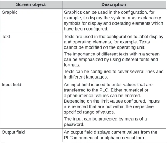
The configuration software contains screen objects, listed in the table below, which can be used to create screens.
Screen object Description
Graphic Graphics can be used in the configuration, for example, to display the system or as explanatory symbols for display and operating elements which have been configured.
Text Texts are used in the configuration to label display and operating elements, for example. Texts cannot be modified on the operating unit. The importance of different texts within a screen can be emphasized by using different fonts and formats.
Texts can be configured to cover several lines and in different languages.
Input field An input field is used to enter values that are transferred to the PLC. Either numerical or alphanumerical values can be entered.
Depending on the limit values configured, inputs are rejected that are not within the respective specified range of values.
Description Screen object
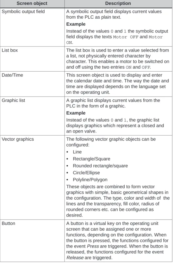
Symbolic output field A symbolic output field displays current values from the PLC as plain text.
Example
Instead of the values 0 and 1 the symbolic output field displays the texts Motor OFF and Motor ON.
List box The list box is used to enter a value selected from a list, not physically entered character by
character. This enables a motor to be switched on and off using the two entries ON and OFF.
Date/Time This screen object is used to display and enter the calendar date and time. The way the date and time are displayed depends on the language set on the operating unit.
Graphic list A graphic list displays current values from the PLC in the form of a graphic.
Example
Instead of the values 0 and 1, the graphic list displays graphics which represent a closed and an open valve.
Vector graphics The following vector graphic objects can be configured: Line Rectangle/Square Rounded rectangle/square Circle/Ellipse Polyline/Polygon
These objects are combined to form vector graphics with simple, basic geometrical shapes in the configuration. The type, color and width of the lines and the transparency, fill color, radius of rounded corners etc. can be configured as desired.
Button A button is a virtual key on the operating unit screen that can be assigned one or more functions, depending on the configuration. When the button is pressed, the functions configured for the event Press are triggered. When the button is released, the functions configured for the event
Product Description
Description Screen object
Status button A Status button is a display and operating element which has one of two states: Touched and Untouched. The states can be indicated by means of text or graphics.
The Status button can be configured to be locking (switch function) or non-locking (keying function). Switch A switch serves to enter and display a binary
status. It can only be switched on or off.
Invisible button An invisible button is a transparent button that is not displayed on the operating unit. If invisible buttons are positioned, for example, on a graphic, only parts of this graphic can be operated; a motor or valve for example.
When an invisible button is pressed, the functions configured for the event Press are triggered. When the button is released, the functions configured for the event Release are triggered. Trend display A trend display provides a particularly clear
representation of process data when displayed as a continual progression.
Several different trend curves can be displayed simultaneously in the trend curve display, e.g. current and archived trend curves.
Bar graph Bar graphs present a value from the PLC in the form of a rectangular area. This makes it possible to recognize from a single glance at the operating unit how far away the current value is from the limits or whether a specified setpoint has been reached. Bar graphs are used, for example, to display fill levels or quantities.
The direction, scaling, bar and background colors, and labeling of the Y axis can be configured as desired. Lines can also be displayed to mark limit values.
Message view Special filter criteria for displaying the volatile message buffer and/or the message archive are configured in the message view.
Simple message view A simple message view can provide a subset of the functionality of a message view. It can be used, for example, to simply realize a message line in a screen.
Description Screen object
Status/Force Status/Force enables direct access to values in the connected PLC (SIMATIC S5 and
SIMATIC S7) via the operating unit and to read and write them. PLC operands can be monitored and changed without having to connect an additional programming unit or PC to the PLC. This is particularly useful during the testing and commissioning phase of your configuration. Password list The password list can be used to display, enter
and modify passwords on the operating unit. Recipe view A recipe view can be used to create, save and
transfer data records on the operating unit. Slider control Use a slider control to enter and display numerical
values in analog form. To enter values, move the slider to the required position.
When used as a display element, the value is represented by the position of the slider.
Analog display An analog display indicates numerical values by means of a pointer instrument.
Digital/Analog clock A digital/analog clock enables the system time to be displayed either as digits or as a traditional clock with hands.
Product Description
3.1.2
Messages
Message classes
Messages indicate control-process events and states on the operating unit. ProTool/Pro differentiates between the following message categories:
Event Messages
indicate a status in the process, for example, Motor ON. Event messages are configured.
Alarm Messages
indicate an equipment failure, for example, Motor temperature too high. Alarm messages are configured. Alarm messages must be acknowledged due to their critical nature.
System messages
are triggered by the operating unit. They are not configured. System messages indicate, for example, incorrect operations or communication faults. A selection of important system messages for Windows-based systems is provided in Appendix A.
S7 system messages
provide information on the status of the SIMATIC S7. They are not configured in the ProTool/Pro CS configuration software. Refer to the S7 manual for the error number indicated on the operating panel to determine the cause of the error.
ALARM_S
ALARM_S is an active message procedure. If an alarm occurs, the CPU actively issues the respective message to all the network participants which are logged on. This means that the operating unit is relieved of continuous polling of the message area. ALARM_S messages are not configured in ProTool/Pro CS but in STEP 7. The message numbers are automatically assigned during configuration in STEP 7. The unique assignment of the message text is made according to these numbers. The display of ALARM_S messages on the operating unit can only be configured when a SIMATIC S7 PLC is used and the ProTool/Pro CS configuration software has been integrated in STEP 7.
Buffering messages
All message events (arrived, departed, acknowledged) are stored in an internal volatile buffer. This buffer can contain 1024 message events. If a message archive has been configured, the message events are also stored in this message archive. The message archive capacity is only restricted by the storage medium.
Display messages
The events stored in the message buffer can be displayed according to different criteria. The following predefined objects are available for display purposes:
Message line (refer to Page 6-12) Message window (refer to Page 6-12) Message page (refer to Page 6-14) Message buffer (refer to Page 6-15) Message view
– Message view with full functionality (refer to Page 6-16)
– Simple message view with restricted functionality (refer to Page 6-17)
3.1.3
Tags
Definition
Tags are fixed memory locations on the operating unit into which values are written and/or read. The actions can be initiated from the PLC or by operations executed on the operating unit.
Global and local tags
A fundamental distinction is made between the following types of tag: Global tags
Global tags are process tags. They are used to establish a connection to the PLC. An address must be assigned in the PLC for each global tag. The operating unit accesses this address to write to or read from it.
Local tags
Local tags have no connection to the PLC. They are only available in the operating unit. Local tags are created in order, for example, to enter limit values via the operating unit.
VB script tags
Internal script tags must be defined with the DIM instruction and are only valid within the VB Script procedure.
Product Description
3.1.4
Functions
Purpose
The ProTool/Pro CS configuration software provides a range of functions which can be used in a project. Functions serve to:
set up the process on a process-specific basis control the process
utilize properties of the operating unit
define system settings on-line on the operating unit
Using functions
Functions are linked to objects within the project, e.g. to buttons, keys, fields or screens. In addition, events must be defined that trigger the functions, for example “Press button” or “Release button”.
Not every function is available for each object. ProTool/Pro CS only provides those functions in the selection list which can actually be used with the particular object being configured.
When configuring functions, it is normally necessary to enter input parameters. For example, in the case of the function Select Screen, an input parameter is the name of the screen to be opened.
3.1.5
Printing
Print functions
The following print functions are available in Online mode: Hardcopy
If the Hardcopy function is implemented in the configuration, the screen currently displayed can be printed out.
Print messages
Each message event which occurs (arrived, departed, acknowledged) is logged via the printer.
Print protocol
(Refer to Chapter 3.1.7) Print message buffer
3.1.6
Archiving
Purpose
Different archives can be set up for message events and tags: Message events
these relate to arriving, departing and acknowledging in the case of alarm messages
Tags
these can be assigned to a previously defined archive during configuration. During the process, it is necessary to specify when the value of the tag should be written to the archive.
Alternatively, it is possible to specify the name of a file or an existing database for the archives.
Archive storage in a CSV file
ProTool/Pro RT enables archives to be stored in a CSV file. In CSV format, table columns are separated by hyphens and table rows are terminated by a line feed. This enables archive data to be evaluated or edited easily, e.g. using an external text editor or a spreadsheet program.
In order to store the archive data in a CSV file, a directory must be specified in the ProTool/Pro CS configuration software. The storage location is thus referenced.
Archive storage in a database
ProTool/Pro RT also enables archives to be stored directly in a database instead of a file. This means that the entire functionality of the database is available for further processing and evaluating the archive data. The following databases have been tested and approved for ProTool/Pro RT:
MS Access 97 MS SQL Server 6.5
In order to store archive data, a so called Data Source Name (DSN) must be specified in the ProTool/Pro CS configuration software instead of a directory name. The DSN is provides a precise reference to the database and its location.
Product Description
The following example emphasizes the necessary steps when using MS Access:
Step Procedure
1 Configuring the archive in ProTool/Pro CS
Select the Archive dialog, Settings tab, Database memory location for the archive to be stored in a database.
Enter the name in Data Source Name under which the archive should be registered.
Enter the size of the archive and select the option FIFO buffer. 2 Configure the database on the runtime computer
Call in the ODBC32 configuration program from the Windows Start menu under Settings → Control Panel.
Insert a new User DSN by using the Add button. The required database driver must be selected.
Enter the DSN configured in ProTool/Pro CS in the dialog which appears. This dialog is specific to the database.
No other settings are necessary for MS Access.
More settings must be defined for MS SQL servers. Please refer to the database manual for information on these settings.
Note
The number of possible archives can also be restricted by the databases used, e.g. by the configuration, license, etc.
3.1.7
Protocols
Application
Protocols are used to document process data and completed production cycles. The ProTool/Pro CS configuration software defines the content and layout of the various protocols and configures the event which should trigger protocol printout. In this way, for example, it is possible to configure a protocol which is printed at the end of a shift in order to document non-production times. It is also possible to configure a protocol which can be used for documentation purposes within the scope of product or quality tests.
Triggering events
Printout of the protocol during runtime is triggered either automatically (e.g. via a scheduler) or manually (e.g. via a function key or softkey). The following events can be configured to trigger printout:
Scheduler
Softkey/Function key Modification of a tag value Script
Print message buffer
A protocol can be configured so that it can be used to print the message buffer contents. The following can be configured: the message categories to be printed, the columns (message number, date, time, message text, etc.) and sorting (most recent or oldest message first).
Special printing features
In order that the protocol is correctly printed, the printer connected during runtime must support the paper format and layout of the protocol.
In the protocol, a tag value is read out and printed at the moment of printing. In the case of protocols covering several pages, there may be a longer period of time between printing the first and last page. Therefore, it is possible that the same tag is assigned a different value on the last page than on the first.
Product Description
3.1.8
Scripts
Purpose
ProTool/Pro CS provides an interface for scripting with Microsoft Visual Basic Script (VB Script). The VB scripts can be used to extend the configuration software by adding customized functions. VB scripts are used similarly to functions.
Documentation
The detailed Microsoft documentation on VB scripts is contained within the scope of the ProTool/Pro CS configuration software supplied.
3.2
Connecting to the PLC
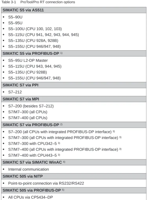
Overview
Table 3-1 provides an overview of the connection options of the SIMATIC ProTool/Pro RT runtime software with various PLCs: Table 3-1 ProTool/Pro RT connection options
SIMATIC S5 via AS511 S5–90U
S5–95U
S5–100U (CPU 100, 102, 103)
S5–115U (CPU 941, 942, 943, 944, 945) S5–135U (CPU 928A, 928B)
S5–155U (CPU 946/947, 948) SIMATIC S5 via PROFIBUS-DP 1)
S5–95U L2-DP Master
S5–115U (CPU 943, 944, 945) S5–135U (CPU 928B)
S5–155U (CPU 946/947, 948) SIMATIC S7 via PPI
S7–212
SIMATIC S7 via MPI
S7–200 (besides S7–212) S7/M7–300 (all CPUs) S7/M7–400 (all CPUs)
SIMATIC S7 via PROFIBUS-DP 2)
S7–200 (all CPUs with integrated PROFIBUS-DP interface) 3)
S7/M7–300 (all CPUs with integrated PROFIBUS-DP interface) 3)
S7/M7–300 with CPU342–5 3)
S7/M7–400 (all CPUs with integrated PROFIBUS-DP interface) 3)
S7/M7–400 with CPU443–5 3)
SIMATIC S7 via SIMATIC WinAC 4)
Product Description
Table 3-1 ProTool/Pro RT connection options, continued OPC 6)
S Client/Server
Allen Bradley via DF1, DH+ (KF2) and DH485 (KF3)
S PLC-5
S SLC 500 Mitsubishi
S FX
Telemecanique via Adjust and Uni-Telway
S TSX
1) Special function block required (see User’s Guide entitled Communication for Windows-based Systems)
2) ProTool/Pro RT is an active node; communication takes place using the S7 protocol 3) Refer to Catalog ST70
4) Only with WindowsR NT
5) Special application required (see User’s Guide entitled Communication for Windows-based Systems)
6) Only with WindowsR NT and WindowsR 2000. Not for OP 37/Pro
Information on how to link the software to the various types of PLC can be found in the user’s guide entitled “Communication for Windows-based Systems”.
Requirements for Commissioning
Which components do you need?
The SIMATIC ProTool/Pro CD contains both the configuration software for all operating units and the runtime software to run the configuration. If the
configuration should be run on an operating unit without the runtime software being installed at the factory (e.g. PC or SIMATIC Panel PC), both the runtime software and the authorization must have been installed on the system beforehand. The authorization for PCs must be ordered separately as a license disk.
The license is subdivided according to the number of process tags, known as “power tags”. A process tag contains a connection to the PLC. Licenses are available for power tags with 128, 256, 512 and 2048 tags. In addition, upgrades (power packs) are available for upgrading to a greater number of power tags.
4.1
Scope of Delivery
Operating units supported
SIMATIC ProTool/Pro supports all SIMATIC operating units and Windows-based PCs. These operating units are divided into the following groups:
S Text Displays TD 17
S Text-based display operator panels OP 3, OP 5, OP 7, OP 15A, OP 15C, OP 17
S Graphic display operator panels OP 25, OP 27, OP 35, OP 37
S Touch panels
TP 27-6, TP 27-10, TP 37
S Windows-based systems – TP 170A, MP 270, OP 37/Pro
– SIMATIC Panel PCs, e.g. FI 25, FI 45, PC 670, PC 670T – Standard PC
S C7 units
C7-621, C7-623, C7-624, C7-626, C7-633, C7-634
The subsequent descriptions in this guide only relate to the following Windows-based systems:
S OP 37/Pro
S SIMATIC Panel PC
S Standard PC
For detailed descriptions of the hardware and operation of the SIMATIC operating units MP 270 and TP 170A, please refer to the respective equipment manual. An overview of the SIMATIC HMI documentation available is provided in the
Appendix B of this guide.
Supported PLCs
An overview of the runtime software connection options to various PLCs is provided in Chapter 3.2.
Requirements for Commissioning
4.2
System Requirements for PCs
Operating system
SIMATIC ProTool/Pro RT can be run under the following operating systems:
S MicrosoftR WindowsR 95 with Service Pack 1 (Build 950a) or higher
S MicrosoftR WindowsR 95 OSR 2 (Build 950b) or higher
S MicrosoftR WindowsR 98
S MicrosoftR WindowsR 2000
S MicrosoftR WindowsR NT 4.0 with Service Pack 4 or 5 Note
Service Pack 1 must not be installed on a Windows 95R OSR 2 (Build 950b) or higher.
If the required MicrosoftR Service Pack is not available on the PC, it can be installed directly from the SIMATIC ProTool/Pro CD.
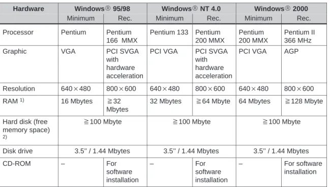
Hardware
The PC hardware must fulfill the following requirements in order to operate the ProTool/Pro RT runtime software:
Hardware WindowsR 95/98 WindowsR NT 4.0 WindowsR 2000
Minimum Rec. Minimum Rec. Minimum Rec.
Processor Pentium Pentium 166 MMX Pentium 133 Pentium 200 MMX Pentium 200 MMX Pentium II 366 MHz
Graphic VGA PCI SVGA
with hardware acceleration
PCI VGA PCI SVGA with hardware acceleration
PCI VGA AGP
Resolution 640 480 800 600 640 480 800 600 640 480 800 600 RAM 1) 16 Mbytes y32
Mbytes
32 Mbytes y64 Mbyte 64 Mbytes y128 Mbyte
Hard disk (free memory space)
2)
y100 Mbyte y100 Mbyte y100 Mbyte
Disk drive 3.5’’ / 1.44 Mbytes 3.5’’ / 1.44 Mbytes 3.5’’ / 1.44 Mbytes
CD-ROM – For software installation – For software installation – For software installation
1) The amount of RAM required mainly depends on the size of the project, which is largely dependent on the size of the graphics used.
2) Without taking archives into account. In addition to the space for ProTool/Pro RT, WindowsR also requires a certain amount of free hard disk space, i.e. memory space must be reserved for the swap file. The following equation has proved applicable:
Size of swap file = 3 size of RAM.
Requirements for Commissioning
4.3
Electrical Installation
Connecting an OP 37/Pro to the PLC
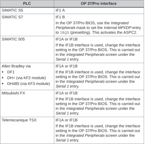
The OP 37/Pro is connected to the PLC via the IF1A or IF1B interface. The interface to be used depends on the design (RS232, RS422 or RS485).
Table 4-1 indicates which PLC can, in principle, be connected to which interface of the OP 37/Pro. For more detailed information on this, please refer to the OP 37/Pro Equipment Manual.
Table 4-1 Using the OP37/Pro interfaces
PLC OP 37/Pro interface
SIMATIC S5 IF1 A
SIMATIC S7 IF1 B
In the OP 37/Pro BIOS, use the Integrated Peripherals mask to set the Internal MPI/DP entry to IRQ5 (presetting). This activates the ASPC2. SIMATIC 505 IF1A or IF1B
If the IF1B interface is used, change the interface setting in the OP 37/Pro BIOS. This is carried out in the Integrated Peripherals screen under the Serial 1 entry.
Allen Bradley via
S DF1
S DH+ (via KF2 module)
S DH485 (via KF3 module)
IF1A or IF1B
If the IF1B interface is used, change the interface setting in the OP 37/Pro BIOS. This is carried out in the Integrated Peripherals screen under the Serial 1 entry.
Mitsubishi FX IF1A or IF1B
If the IF1B interface is used, change the interface setting in the OP 37/Pro BIOS. This is carried out in the Integrated Peripherals screen under the Serial 1 entry.
Telemecanique TSX IF1A or IF1B
If the IF1B interface is used, change the interface setting in the OP 37/Pro BIOS. This is carried out in the Integrated Peripherals screen under the Serial 1 entry.
Connecting a PC to the PLC
The PC is connected to the PLC via one of the interfaces COM1 to COM4. Please refer to the hardware manual provided by the manufacturer for instructions on how to carry out electrical installation of your PC. A communications processor is required to connect the PC to SIMATIC S7.
Table 4-2 indicates which communications processors are approved for use with the PC.
Table 4-2 Approved communications processors
Communications processor SIMATIC S5 via PROFIBUS-DP
SIMATIC S7
CP5611 1) 4 4
CP5511 1) 4 4
CP5412 – 4
1) Installation instructions can be found on Page 5-8
Table 4-3 indicates the basic options for connecting the PC to the PLC. Detailed information on connection to the PLC and cables to be used is provided in the online help to the ProTool/Pro CS configuration software and in the Communication for Windows-based Systems user’s guide.
Table 4-3 Using the PC’s interfaces
PLC Interface on PC
SIMATIC S5 via AS511 COM1 to COM4
An RS232/TTY converter cable is required. SIMATIC S5 via
PROFIBUS–DP
Via communications processor (see Table 4-2)
SIMATIC S7 Via communications processor (see Table 4-2)
SIMATIC 505 COM1 to COM4
OPC Network card
Allen Bradley via
S DF1
S DH+ (via KF2 module)
S DH485 (via KF3 module)
Commissioning ProTool/Pro Runtime
Initial startup
The procedure for commissioning is dependent on whether the operating unit is a ready-to-operate unit with the runtime software installed at the factory (e.g.
OP37/Pro, FI 25, FI 45) or a PC on which the runtime software must be installed by the user.
S Ready-to-operate SIMATIC operating unit
The ready-to-operate SIMATIC operating units are those in which the operating system and ProTool/Pro RT runtime software are fully installed at the factory. An authorization may not be necessary for the runtime software or it is supplied with the unit, depending on the unit concerned.
S SIMATIC operating unit with preinstalled runtime software
When commissioning the SIMATIC operating units PC 670 and PC 670T, the runtime software must be installed from the operating unit hard disk using the Setup program. An installation CD is not necessary.
Authorization for the runtime software is acquired with the operating unit; it is enclosed with the unit.
S PC without runtime software
If a PC is used, the runtime software must be installed from the SIMATIC ProTool/Pro CD. In addition, an authorization for the runtime software is required for each PC. The authorization must be ordered separately.
Note
The SIMATIC Panel PCs described in this guide are either ready-to-operate systems or unit models with preinstalled runtime software.
This guide does not apply to SIMATIC Panel PCs without preinstalled runtime software.
Procedure
The initial commissioning is organized into three steps. Not all the steps described below are relevant to all the operating units.
Step Procedure Operating unit
1 Install and configure the WindowsR operating system (Chapter 5.1)
PC
2 Install the ProTool/Pro RT runtime software (Chapter 5.2)
PC
SIMATIC Panel PC 3 Download, test and start the project (Chapter 5.5) All
Save configuration
The operating unit hard disk may cease to function after several years of use in a hostile industrial environment. In order to ensure that all the programs and settings can be reinstalled on a new hard disk without any problems, a detailed description is enclosed with the unit explaining how to make a backup copy of the configuration defined the hard disk.
Carry out the backup procedure according to the instructions set out in the description so that the operating unit is ready for use after replacing the hard disk and installing the backup data.
Commissioning ProTool/Pro Runtime
5.1
Installing and Configuring Windows
The following instructions describe the procedure for installing and configuring WindowsR. These steps are necessary for the ProTool/Pro RT runtime software to run correctly. Make a note of all the settings so that the runtime software can be run if the operating unit hard disk needs to be replaced for any reason.
Step Procedure
1 Install Windows (PC only)
Information on commissioning WindowsR is provided in the Windows manual supplied.
2 Install service packs 1) (PC only) S WindowsR 95
Install Service Pack 1 for WindowsR 95; this is contained on the SIMATIC ProTool/Pro CD supplied. Start the following program on the CD-ROM:
\servicep\win95\deutsch\setup.exe
This program guides the user through the installation procedure. This directory contains documents from Microsoft that give a detailed description of the installation procedure.
S WindowsR NT
Install service Pack 5 for Windows NT; this is contained on the SIMATIC ProTool/Pro CD supplied. Start the following program on the CD-ROM:
\servicep\winnt\deutsch\nt4sp5_i.exe
This program guides users through the installation procedure. This directory contains documents from Microsoft, that give a detailed description of the installation procedure.
3 Install printer driver
The ProTool/Pro RT runtime software can be used with any printer for which a corresponding Windows printer driver is available. The printer must be installed under Windows as the default printer because ProTool/Pro RT only accesses the standard printer. No settings have to be made for the printer in the runtime software itself.
The printer driver and installation instructions for your printer are supplied by the printer manufacturer. Windows itself actually includes suitable printer drivers for many printers. The printer drivers can be set up via Start → Settings→ Printer→ New printer. The printer must be specified as the default printer when installing it.
Procedure Step
Define the following settings to enable messages to be printed line by line:
For WindowsR95/98:
The Forward print jobs to printer option must be set under printer properties. To do this, select the Properties dialog of the printer. Click the Spool Settings button on the Details tab. The dialog Settings for printing in background opens, in which to select the Print directly to the printer option.
For WindowsR NT and WindowsR 2000:
The Print directly to the printer option must be set under the printer properties. To do this, select the dialog Properties of the printer. Click the Print directly to the printer option on the Print job scheduling tab.
4 Activate multilanguage support 2)
In the case of certain languages with special character sets, such as Greek, Polish, Russian, Slovenian, Czech or Hungarian, the
multilanguage support must be activated if WindowsR95/98 is used. To do this, select Start → Settings → Control Panel. Activate
multilanguage support under Add/Remove Programs → Windows Setup → Multilanguage Support.
5 Setting the time zone
Ensure that the correct time zone is set on the PC on which the runtime software is to run. To set the time zone in Windows, select Start → Settings → Control Panel→ Date/Time → Time Zone.
6 Set screen saver (option)
The majority of modern monitors no longer need a screen saver, indeed a screen saver can actually be harmful to the CRT. These monitors have a power management function which means they switch
themselves off as soon as the video signal has not been changed for a user-defined period of time. A conventional screen saver prevents or at least delays activation of this switch-off function that can lengthen the service life of the screen. However, if a screen saver is required, only the standard screen savers incorporated into Windows are approved for use with ProTool/Pro RT.
1) Not necessary for WindowsR98
Commissioning ProTool/Pro Runtime
5.2
Install ProTool/Pro RT
Note
Chapter 5.2 is only relevant for operating units in which the runtime software has not been installed at the factory (e.g. PC 670 or PC).
5.2.1
SIMATIC Panel PC 670 and PC 670T
Installation
All the files required to install the runtime software are already contained in the Backup directory on the operating unit hard disk. An installation CD is not necessary.
Proceed as follows to install the runtime software using the Setup program:
Step Procedure
1 Access the Backup directory and start the Setup program on Disk1. 2 Follow the installation instructions displayed on the screen and 3 install the license when prompted.
5.2.2
PC Without Runtime Software
Condition
The ProTool/Pro RT runtime software is contained on the SIMATIC ProTool/Pro CD. The runtime software requires a license to be able to run it. This must be ordered separately. If no license has been ordered, ProTool/Pro RT can only run in Demo mode. When running in Demo mode, a message appears at regular intervals stating that the runtime software is not licensed.
A detailed description on installation of the license disk is provided in the documentation enclosed entitled Start-up guide Copy Protection.
Installation
Proceed as follows to install the runtime software:
Step Procedure
1 Install the runtime software from the CD.
If the ‘autorun’ function for your CD-ROM drive is activated, the CD browser starts automatically after inserting the CD. If ‘autorun’ is not active, start the install.exe program in the root directory of the CD-ROM.
2 Use Language to select the user interface language of the Setup program.
3 Select Installation and start the installation with ProTool/Pro RT. 4 Follow the installation instructions displayed on the screen and 5 install the license when prompted.
If there is no license available for the runtime software during
installation, it can be loaded later. Call in the authorsw.exe program on the license disk and install the license.
Commissioning ProTool/Pro Runtime
5.2.3
Communication
Connection to the PLC
ProTool/Pro RT supports communication with the PLCs listed in 3.2. Connect the operating unit to the PLC in order that the project can also be tested when connected to the PLC. The simulator can also be started to test the project (Page 5-11). In this case, there is no need for a connection to the PLC.
Communication with PROFIBUS-DP
If the ProTool/Pro RT runtime software is to be run on SIMATIC S7 using the profile PROFIBUS-DP and no connection is established, it is possible that the bus
parameters are incorrect.
Proceed as follows to reset the parameters to their default values:
Step Procedure
1 Activate the Start menu and select Settings → Control Panel and open the Set PU/PC interface dialog.
PROFIBUS must be selected in Component configuration used. 2 Click on the Properties button.
In Network Parameters, DP is selected as the profile.
3 Select Universal (DP/FMS) and confirm the selection with OK. 4 Click on the Properties button again.
In Profile, select DP again and confirm the selection with OK.
MPI setting
Step Procedure
1 Activate the Start menu and select Settings → Control Panel and open the Set PU/PC interface dialog.
2 Press the Properties button and set the parameters for the operating unit on the MPI Network tab control so that it is the only master on the bus.
Note
If several operating units must be operated via MPI, ensure that only one unit is the master on the bus.
5.3
Retrofitting a Communication Processor
Purpose
The steps described below are only necessary if a CP5511 or CP5611 communication processor is retrofitted to enable connection to a SIMATIC S7.
Recommended procedure
First, install the runtime software before installing the communications processor. Proceed as follows:
Step Procedure
1 Install the Runtime software. 2 Switch off the operating unit.
3 Slot in the communications processor. 4 Start up the operating unit again.
The communications processor is detected and configured automatically (Plug&Play function) when the PC is booted.
If the communications processor is installed before the runtime software, the communications processor cannot be activated by the installation program. Remedy:
Step Procedure
1 Activate the Start menu, select Settings → Control Panel→ System and select the device manager.
2 Remove the unrecognized component, PCI Network Controller, from the list.
3 Start up the operating unit again.
The communications processor is detected and configured automatically (Plug&Play function) when the PC is booted.
Commissioning ProTool/Pro Runtime
5.4
Settings for the OP 37/Pro
Settings in BIOS
Different settings must be defined in the BIOS of the OP 37/Pro, according to the connection used. In the case of serial connections, the corresponding COM interface must be activated.
Detailed information on this is provided in the OP 37/Pro Equipment Manual, Communication for Windows-based Systems User’s Guide and in the online help for the ProTool/Pro CS configuration software.
Direct key module
The optional direct key module for the OP 37/Pro is not supported by the ProTool/Pro RT runtime software. The hardware based control of the direct key module outputs via the OP 37/Pro keyboard can be used, however, without restrictions.
5.5
Downloading, Testing and Commissioning the Project
5.5.1
Scenarios
Overview
ProTool/Pro RT is the application with which a project can be run on-line. However, this project must first be created with the ProTool/Pro CS configuration software. Detailed information on how to create projects can be found in the online Help of the ProTool/Pro CS configuration software and in the ProTool Configuring Windows-based Systems User’s Guide.
A number of scenarios are possible for testing the project:
S The ProTool/Pro RT runtime software is installed on the same PC as the ProTool/Pro CS configuration software (Page 5-10).
S The ProTool/Pro RT runtime software is installed on a different PC from the ProTool/Pro CS configuration software. In this case, the project must be downloaded from the configuration computer to the target PC (Page 5-10).
S The project runs on the OP37/Pro. In this case, the project must be downloaded from the configuration computer to the OP37/Pro.
Configuration software and runtime software are on the same PC
Create the project, for example, under the name Myproject.pdb, and then compile it. Once compilation has been completed, a compiled file with the extension *.fwd is stored in the same directory as the project file (for example,
Myproject.fwd). Double-click this file to start the ProTool/Pro RT runtime software with this compiled project.
If the PC is connected to the PLC,the project can be tested immediately in connection with the PLC.
Information on how to simulate the project without a PLC using the simulation program is provided in Chapter 5.5.2.
Configuration software and runtime software are on different systems
Create the project, for example, under the name Myproject.pdb, and then compile it. Once compilation has been completed, a compiled file with the
extension *.fwd, e.g. Myproject.fwd is stored in the same directory. Windows provides the following options for downloading the compiled files:
S Copy the *.fwd file on to a floppy disk and then from the disk to the target system (PC). If the project is too large for one disk, use the disk transfer option.
S Disk transfer:
In ProTool/Pro CS, select the menu option File → Download and select drive A:\ in the Destination Directory dialog. The operation-capable project file is
transferred to one or more disks in a compressed form.
In order to decompress the compressed project file on the target device, activate the Start menu and select SIMATIC → ProTool/Pro RT → ProTool/Pro Disk Transfer. Select the compressed file, e.g. Myproject.f00 in the Transfer dialog and enter the destination directory in which the decompressed project file should be copied.
S Copy the file *.fwd file from WindowsR 95/98 to the target system via a parallel or serial cable using the Direct Cable Connection option.
S Copy the file *.fwd file from Windows R NT or WindowsR 2000 to the target system via a parallel or serial cable using the Dial-Up Connection option.
S Copy the *.fwd file to the target system via a network.
Double-click on the compiled project file to start the runtime software on the target system.
Commissioning ProTool/Pro Runtime
5.5.2
Simulation of a Project
Function
The scope of delivery in respect of the ProTool/Pro RT runtime software contains a simulator with which to test the project without a PLC. The simulator is a separate application. It enables the user to test whether the screens, screen objects, messages, etc. which have been configured function correctly.
The simulator simulates the PLC and
S modifies the values of configured tags in a definable way:
e.g. incrementally, decrementally, sinusoidally, randomly or by shift bits
S sets bits in bit-by-bit organized area pointers1):
By shifting the bits in the two area pointers Event Messages and Alarm
Messages, it is possible, for example, to trigger all the configured messages on the operating unit.
A condition for simulation is that the ProTool/Pro RT runtime software is also installed on the configuration computer.
Principle
The following steps describe the basic procedure for simulating a project. Step-by-step instructions are provided in Table 5-1.
1. First of all, create a project as is to run later when connected to the PLC. 2. Save and compile the project.
3. Start the simulator directly from the running configuration software by clicking on the icon depicted or via menu options File → Test → Start Simulator. If the simulator is started without having compiled the project beforehand, compilation is automatically triggered.
4. When the project is simulated for the first time, the simulator is started with a new, empty simulation table. If a simulation table already exists for the project, it is opened.
All the settings are saved in simulation table *.sim defined for the simulation of tags and area pointers (refer to Figure 5-1).
5. Now manipulate the project tags and area pointers in the simulation table. 6. It is possible to watch how the values change by switching the task from the
Note
S Not all the configured tags are provided in the simulation table. Only referenced tags are available for the simulation, i.e. only those tags used in the project e.g. in a screen object.
S Since the simulator can only simulate the project offline, i.e. without a
connection to the PLC, the data formats are converted to internal ProTool/Pro CS formats. Therefore, PLC-specific data formats cannot be realized.
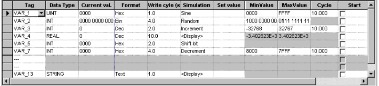
Simulation table
Figure 5-1 Simulation table (example)
Figure 5-1 illustrates an example of a simulation table. All the settings defined in this table for simulating the project can be saved in a file. In this case, select File → Save in the simulator and enter a file name (*.sim).
This means that the project can be simulated again at a later date with saved settings. A condition for this is that the tags and area pointers to be simulated in the project have not be altered in the meantime.
Commissioning ProTool/Pro Runtime
Operate simulator
The following instructions provide a detailed description of the procedures for operating the simulator.
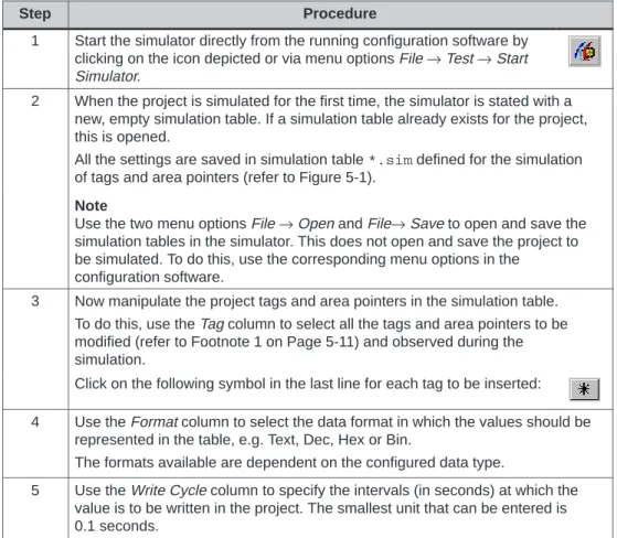
Table 5-1 Simulator operation, step-by-step
Step Procedure
1 Start the simulator directly from the running configuration software by clicking on the icon depicted or via menu options File → Test → Start Simulator.
2 When the project is simulated for the first time, the simulator is stated with a new, empty simulation table. If a simulation table already exists for the project, this is opened.
All the settings are saved in simulation table *.sim defined for the simulation of tags and area pointers (refer to Figure 5-1).
Note
Use the two menu options File → Open and File→ Save to open and save the simulation tables in the simulator. This does not open and save the project to be simulated. To do this, use the corresponding menu options in the
configuration software.
3 Now manipulate the project tags and area pointers in the simulation table. To do this, use the Tag column to select all the tags and area pointers to be modified (refer to Footnote 1 on Page 5-11) and observed during the simulation.
Click on the following symbol in the last line for each tag to be inserted: 4 Use the Format column to select the data format in which the values should be
represented in the table, e.g. Text, Dec, Hex or Bin.
The formats available are dependent on the configured data type.
5 Use the Write Cycle column to specify the intervals (in seconds) at which the value is to be written in the project. The smallest unit that can be entered is 0.1 seconds.
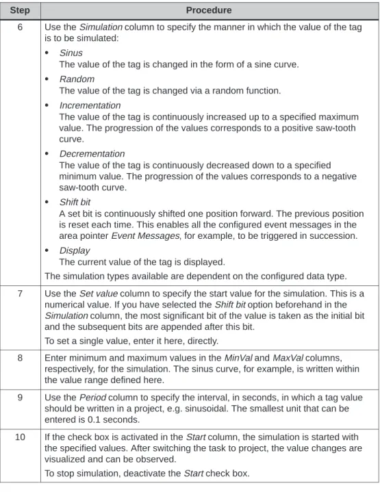
Table 5-1 Simulator operation, step-by-step, continued Procedure Step
6 Use the Simulation column to specify the manner in which the value of the tag is to be simulated:
S Sinus
The value of the tag is changed in the form of a sine curve. S Random
The value of the tag is changed via a random function. S Incrementation
The value of the tag is continuously increased up to a specified maximum value. The progression of the values corresponds to a positive saw-tooth curve.
S Decrementation
The value of the tag is continuously decreased down to a specified minimum value. The progression of the values corresponds to a negative saw-tooth curve.
S Shift bit
A set bit is continuously shifted one position forward. The previous position is reset each time. This enables all the configured event messages in the area pointer Event Messages, for example, to be triggered in succession. S Display
The current value of the tag is displayed.
The simulation types available are dependent on the configured data type. 7 Use the Set value column to specify the start value for the simulation. This is a
numerical value. If you have selected the Shift bit option beforehand in the Simulation column, the most significant bit of the value is taken as the initial bit and the subsequent bits are appended after this bit.
To set a single value, enter it here, directly.
8 Enter minimum and maximum values in the MinVal and MaxVal columns, respectively, for the simulation. The sinus curve, for example, is written within the value range defined here.
9 Use the Period column to specify the interval, in seconds, in which a tag value should be written in a project, e.g. sinusoidal. The smallest unit that can be entered is 0.1 seconds.
10 If the check box is activated in the Start column, the simulation is started with the specified values. After switching the task to project, the value changes are visualized and can be observed.
Commissioning ProTool/Pro Runtime
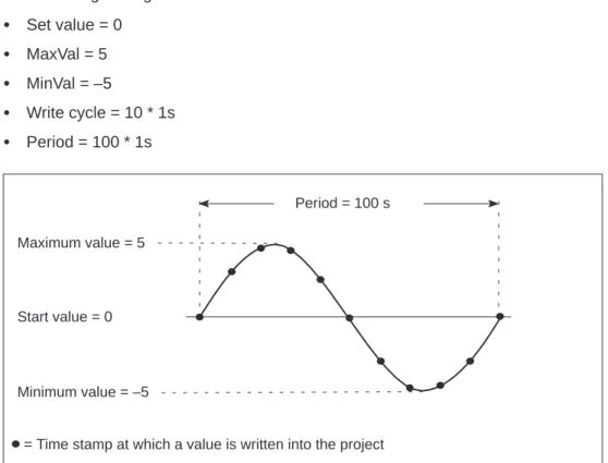
Example of a simulation
The example in Figure 5-2 uses a sine curve to illustrate how the values of a tag are written into the configuration in accordance with the settings in the simulator. The following settings have been made in the simulator:
S Set value = 0 S MaxVal = 5 S MinVal = –5 S Write cycle = 10 * 1s S Period = 100 * 1s Start value = 0 Maximum value = 5 Minimum value = –5 Period = 100 s
= Time stamp at which a value is written into the project
5.6
Starting a Project
Running a project in online operation
Once a project has been created, there are a number of different options with which to start it. A condition for this is that the compiled project is initially
downloaded to the target system in cases where the configuration computer is not simultaneously the target system.
S Double-click on the *.fwd file generated. In this way, the ProTool/Pro RT runtime software is started with the selected file.
S Call in the ProTool/Pro RT runtime software under the program group SIMATIC
→ SIMATIC ProTool/Pro → SIMATIC ProTool Pro RT. The project file to be started can be selected when the runtime software is running.
S Call in the ProTool/Pro RT runtime software from the command line. The command could, for example, be as follows:
c:\siemens\ptprorun\ptprorun.exe c:\proj\myproject.fwd S If a project should be opened directly following startup of the runtime software,
the file must be entered in the initialization file ptprorun.ini. The initialization file is located in the same directory as the ProTool/Pro RT runtime software. Enter the name of the project in the [configuration] section. The line entered could read as follows:
LoadConfigFile=MyProject.fwd
Set up program icon
If the user wants to be able to start the project from the desktop by clicking on the program icon, the following settings must be made:
Step Procedure
1 Position the mouse on a free area of the desktop and click the right-hand mouse button. Select New → Link from the context menu which appears.
2 Click on the Browse button in the subsequent dialog and select the program ptrorun.exe.
3 Enter a name for the icon in the next dialog which appears. 4 Click on the Complete button.
5 Click on the new icon with the right mouse button and select menu option Properties from the context menu which appears. Enter the ProTool/Pro RT runtime software and the project to be started in the Target field. The call could appear as follows, for instance:
Commissioning ProTool/Pro Runtime
5.7
Further Downloading Options
Set up direct cable connection
A direct cable connection between PCs enables the transfer of files from one PC to another. This method of data transfer can also be used to download a compiled project file. A direct cable connection must be set up on both computers to be connected. The parallel cable required for the direct cable connection can be purchased from Siemens. Alternatively, it is possible to set up a direct cable connection using a standard, commercially available, serial null modem cable. Tables 5-2 and 5-3 provide a step-by-step description of how to configure the runtime PC (PC on which the configuration runs) and the configuration PC (PC on which the configuration was created) for a direct PC cable connection.
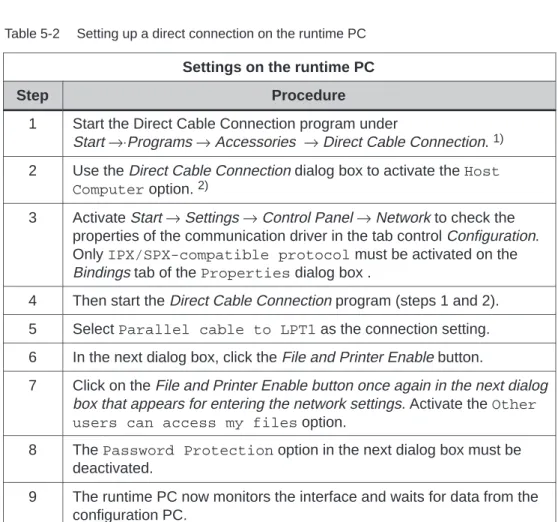
Table 5-2 Setting up a direct connection on the runtime PC Settings on the runtime PC
Step Procedure
1 Start the Direct Cable Connection program under
Start →⋅Programs → Accessories → Direct Cable Connection. 1) 2 Use the Direct Cable Connection dialog box to activate the Host
Computer option. 2)
3 Activate Start → Settings → Control Panel → Network to check the properties of the communication driver in the tab control Configuration. Only IPX/SPX-compatible protocol must be activated on the Bindings tab of the Properties dialog box .
4 Then start the Direct Cable Connection program (steps 1 and 2). 5 Select Parallel cable to LPT1 as the connection setting. 6 In the next dialog box, click the File and Printer Enable button.
7 Click on the File and Printer Enable button once again in the next dialog box that appears for entering the network settings. Activate the Other users can access my files option.
8 The Password Protection option in the next dialog box must be deactivated.
9 The runtime PC now monitors the interface and waits for data from the configuration PC.
Table 5-2 Setting up a direct connection on the runtime PC, continued Procedure
Step
10 Now enable one of the drives or a directory, for example c:\ptproj, so that it can be accessed by the configuration PC. To do this, select the desired directory in the Windows Explorer. Click the right mouse button to open the context menu and select the Enable menu item. Enter an enable name, for example PTProj.
1) If the program is not on the PC, install it before doing anything else. Select Start → Settings → Control Panel → Add/Remove Programs. Then select the Windows Setup tab, double-click Communications and then activate the Direct Cable Connection check box.
2) If a dial-up network has not been installed, a prompt appears requesting insertion of the Windows CD-ROM. The dial-up network is installed and the PC may be restarted. The direct cable connection is already set up on an OP37/Pro. The directory and enable name set up match those specified in Table 5-2 in Step 10. If this directory will not be used, the directories which will be used on the OP37/Pro must be enabled.
The ProTool/Pro RT runtime software is thus installed on the PC. Data can then be downloaded, e.g. the compiled project file. The next step to take is to install and configure the direct cable connection on the configuration PC.
Table 5-3 Setting up a direct connection on the configuration PC Settings on the configuration PC
Step Procedure
1 Start the Direct Cable Connection program under Start → Programs → Accessories → Direct Cable Connection. 1)
2 In the dialog Direct Cable Connection, mark the option Guest Computer. 2)
3 Activate Start �