SIM800 Series_AT Command
Manual_V1.03
Document Title: SIM800 Series AT Commands Manual
Version: 1.03
Date: 2014-03-28
Status: Release
Document Control ID: SIM800 Series_AT Command Manual_V1.03
General Notes
SIMCom offers this information as a service to its customers, to support application and engineering efforts that use the products designed by SIMCom. The information provided is based upon requirements specifically provided to SIMCom by the customers. SIMCom has not undertaken any independent search for additional relevant information, including any information that may be in the customer’s possession. Furthermore, system validation of this product designed by SIMCom within a larger electronic system remains the responsibility of the customer or the customer’s system integrator. All specifications supplied herein are subject to change.
Copyright
This document contains proprietary technical information which is the property of Shanghai SIMCom Wireless Solutions Ltd, copying of this document and giving it to others and the using or communication of the contents thereof, are forbidden without express authority. Offenders are liable to the payment of damages. All rights reserved in the event of grant of a patent or the registration of a utility model or design. All specification supplied herein are subject to change without notice at any time.
Contents
Version History...14
1 Introduction...19
1.1 Scope of the document ...19
1.2 Related documents...19
1.3 Conventions and abbreviations ...19
1.4 AT Command syntax ...19
1.4.1 Basic syntax ...20
1.4.2 S Parameter syntax...20
1.4.3 Extended Syntax...20
1.4.4 Combining AT commands on the same Command line...20
1.4.5 Entering successive AT commands on separate lines...21
1.5 Supported character sets...21
1.6 Flow control ...21
1.6.1 Software flow control (XON/XOFF flow control)...21
1.6.2 Hardware flow control (RTS/CTS flow control)...22
1.7 Definitions ...22
1.7.1 Parameter Saving Mode ...22
1.7.2 Max Response Time...23
2 AT Commands According to V.25TER ...24
2.1 Overview of AT Commands According to V.25TER ...24
2.2 Detailed Description of AT Commands According to V.25TER ...25
2.2.1 A/ Re-issues the Last Command Given...25
2.2.2 ATA Answer an Incoming Call...25
2.2.3 ATD Mobile Originated Call to Dial A Number...26
2.2.4 ATD><n> Originate Call to Phone Number in Current Memory...28
2.2.5 ATD><str> Originate Call to Phone Number in Memory Which Corresponds to Field <str>...29
2.2.6 ATDL Redial Last Telephone Number Used...31
2.2.7 ATE Set Command Echo Mode ...32
2.2.8 ATH Disconnect Existing Connection...32
2.2.9 ATI Display Product Identification Information ...32
2.2.10 ATL Set Monitor speaker loudness...33
2.2.11 ATM Set Monitor Speaker Mode ...33
2.2.12 +++ Switch from Data Mode or PPP Online Mode to Command Mode ...33
2.2.13 ATO Switch from Command Mode to Data Mode...34
2.2.14 ATP Select Pulse Dialling...34
2.2.15 ATQ Set Result Code Presentation Mode...35
2.2.16 ATS0 Set Number of Rings before Automatically Answering the Call...35
2.2.18 ATS4 Set Response Formatting Character ...36
2.2.19 ATS5 Set Command Line Editing Character...37
2.2.20 ATS6 Pause Before Blind Dialling...38
2.2.21 ATS7 Set Number of Seconds to Wait for Connection Completion...38
2.2.22 ATS8 Set Number of Seconds to Wait for Comma Dial Modifier Encountered in Dial String of D Command ...39
2.2.23 ATS10 Set Disconnect Delay after Indicating the Absence of Data Carrier...39
2.2.24 ATT Select Tone Dialing ...40
2.2.25 ATV TA Response Format ...40
2.2.26 ATX Set CONNECT Result Code Format and Monitor Call Progress ...41
2.2.27 ATZ Reset Default Configuration ...42
2.2.28 AT&C Set DCD Function Mode ...42
2.2.29 AT&D Set DTR Function Mode...43
2.2.30 AT&F Factory Defined Configuration ...43
2.2.31 AT&V Display Current Configuration ...44
2.2.32 AT&W Store Active Profile ...44
2.2.33 AT+GCAP Request Complete TA Capabilities List ...46
2.2.34 AT+GMI Request Manufacturer Identification ...46
2.2.35 AT+GMM Request TA Model Identification ...47
2.2.36 AT+GMR Request TA Revision Identification of Software Release...47
2.2.37 AT+GOI Request Global Object Identification ...48
2.2.38 AT+GSN Request TA Serial Number Identification (IMEI) ...48
2.2.39 AT+ICF Set TE-TA Control Character Framing...49
2.2.40 AT+IFC Set TE-TA Local Data Flow Control ...50
2.2.41 AT+IPR Set TE-TA Fixed Local Rate ...51
2.2.42 AT+HVOIC Disconnect Voice Call Only...52
3 AT Commands According to 3GPP TS 27.007...54
3.1 Overview of AT Command According to 3GPP TS 27.007 ...54
3.2 Detailed Descriptions of AT Command According to 3GPP TS 27.007 ...55
3.2.1 AT+CACM Accumulated Call Meter (ACM) Reset or Query...55
3.2.2 AT+CAMM Accumulated Call Meter Maximum (ACM max) Set or Query ...56
3.2.3 AT+CAOC Advice of Charge ...57
3.2.4 AT+CBST Select Bearer Service Type...58
3.2.5 AT+CCFC Call Forwarding Number and Conditions Control ...59
3.2.6 AT+CCWA Call Waiting Control ...61
3.2.7AT+CEER Extended Error Report ...62
3.2.8 AT+CGMI Request Manufacturer Identification ...65
3.2.9 AT+CGMM Request Model Identification...65
3.2.10 AT+CGMR Request TA Revision Identification of Software Release...66
3.2.11 AT+CGSN Request Product Serial Number Identification (Identical with +GSN)...66
3.2.12 AT+CSCS Select TE Character Set...67
3.2.13 AT+CSTA Select Type of Address ...68
3.2.15 AT+CIMI Request International Mobile Subscriber Identity...69
3.2.16 AT+CLCC List Current Calls of ME...70
3.2.17 AT+CLCK Facility Lock...71
3.2.18 AT+CLIP Calling Line Identification Presentation ...73
3.2.19 AT+CLIR Calling Line Identification Restriction...74
3.2.20 AT+CMEE Report Mobile Equipment Error...75
3.2.21 AT+COLP Connected Line Identification Presentation ...76
3.2.22 AT+COPS Operator Selection...78
3.2.23 AT+CPAS Phone Activity Status...79
3.2.24 AT+CPBF Find Phonebook Entries...80
3.2.25 AT+CPBR Read Current Phonebook Entries ...81
3.2.26 AT+CPBS Select Phonebook Memory Storage...82
3.2.27 AT+CPBW Write Phonebook Entry...83
3.2.28 AT+CPIN Enter PIN...84
3.2.29 AT+CPWD Change Password...85
3.2.30 AT+CR Service Reporting Control ...86
3.2.31 AT+CRC Set Cellular Result Codes for Incoming Call Indication ...87
3.2.32 AT+CREG Network Registration...88
3.2.33 AT+CRLP Select Radio Link Protocol Parameters ...90
3.2.34 AT+CRSM Restricted SIM Access ...90
3.2.35 AT+CSQ Signal Quality Report ...91
3.2.36 AT+VTD Tone Duration...92
3.2.37 AT+VTS DTMF and Tone Generation...93
3.2.38 AT+CMUX Multiplexer Control...94
3.2.39 AT+CNUM Subscriber Number...95
3.2.40 AT+CPOL Preferred Operator List...96
3.2.41 AT+COPN Read Operator Names...97
3.2.42 AT+CFUN Set Phone Functionality...98
3.2.43 AT+CCLK Clock...99
3.2.44 AT+CSIM Generic SIM Access ...99
3.2.45 AT+CALM Alert Sound Mode...100
3.2.46 AT+CALS Alert Sound Select...101
3.2.47 AT+CRSL Ringer Sound Level...102
3.2.48 AT+CLVL Loud Speaker Volume Level ...103
3.2.49 AT+CMUT Mute Control...103
3.2.50 AT+CPUC Price Per Unit and Currency Table...104
3.2.51 AT+CCWE Call Meter Maximum Event ...105
3.2.52 AT+CBC Battery Charge...106
3.2.53 AT+CUSD Unstructured Supplementary Service Data...107
3.2.54 AT+CSSN Supplementary Services Notification ...107
4 AT Commands According to 3GPP TS 27.005...110
4.1 Overview of AT Commands According to 3GPP TS 27.005... 110
4.2.1 AT+CMGD Delete SMS Message...110
4.2.2 AT+CMGF Select SMS Message Format ... 111
4.2.3 AT+CMGL List SMS Messages from Preferred Store...112
4.2.4 AT+CMGR Read SMS Message...115
4.2.5 AT+CMGS Send SMS Message...118
4.2.6 AT+CMGW Write SMS Message to Memory ...119
4.2.7 AT+CMSS Send SMS Message from Storage ...121
4.2.8 AT+CNMI New SMS Message Indications ...122
4.2.9 AT+CPMS Preferred SMS Message Storage ...124
4.2.10 AT+CRES Restore SMS Settings...125
4.2.11 AT+CSAS Save SMS Settings ...126
4.2.12 AT+CSCA SMS Service Center Address ...127
4.2.13 AT+CSCB Select Cell Broadcast SMS Messages...128
4.2.14 AT+CSDH Show SMS Text Mode Parameters ...129
4.2.15 AT+CSMP Set SMS Text Mode Parameters ...130
4.2.16 AT+CSMS Select Message Service...131
5 AT Commands for SIM Application Toolkit ...133
5.1 Overview ...133
5.2 Detailed Descriptions of Commands...133
5.2.1 AT+STKTRS STK Terminal Response...133
5.2.2 AT+STKENVS STK Envelope Command...134
5.2.3 AT+STKCALL STK call setup ...135
5.2.4 AT+STKSMS STK SMS delivery...136
5.2.5 AT+STKSS STK SS setup ...136
5.2.6 AT+STKUSSD STK USSD setup ...137
5.2.7 AT+STKDTMF STK sending DTMF ...137
5.2.8 +STKPCI STK Proactive Command Indication ...138
5.2.9 AT+STKMENU STK Main menu command ...139
5.2.10 AT+STKPCIS STK URC switch command ...139
6 AT Commands Special for SIMCom ...141
6.1 Overview ...141
6.2 Detailed Descriptions of Commands...142
6.2.1 AT+SIDET Change the Side Tone Gain Level...142
6.2.2 AT+CPOWD Power off...143
6.2.3 AT+SPIC Times Remained to Input SIM PIN/PUK...144
6.2.4 AT+CMIC Change the Microphone Gain Level...144
6.2.5 AT+CALA Set Alarm Time...145
6.2.6 AT+CALD Delete Alarm...146
6.2.7 AT+CADC Read ADC ...147
6.2.8 AT+CSNS Single Numbering Scheme ...148
6.2.9 AT+CDSCB Reset Cell Broadcast...148
6.2.11 AT+CFGRI Indicate RI When Using URC ...149
6.2.12 AT+CLTS Get Local Timestamp...150
6.2.13 AT+CLDTMF Local DTMF Tone Generation ...152
6.2.14 AT+CDRIND CS Voice/Data Call Termination Indication ...152
6.2.15 AT+CSPN Get Service Provider Name from SIM ...153
6.2.16 AT+CCVM Get and Set the Voice Mail Number on the SIM ...154
6.2.17 AT+CBAND Get and Set Mobile Operation Band ...155
6.2.18 AT+CHF Configure Hands Free Operation...155
6.2.19 AT+CHFA Swap the Audio Channels ...156
6.2.20 AT+CSCLK Configure Slow Clock ...157
6.2.21 AT+CENG Switch On or Off Engineering Mode ...158
6.2.22 AT+SCLASS0 Store Class 0 SMS to SIM When Received Class 0 SMS ...160
6.2.23 AT+CCID Show ICCID ...161
6.2.24 AT+CMTE Set Critical Temperature Operating Mode or Query Temperature...161
6.2.25 AT+CMGDA Delete All SMS...162
6.2.26 AT+STTONE Play SIM Toolkit Tone...163
6.2.27 AT+SIMTONE Generate Specifically Tone...164
6.2.28 AT+CCPD Enable or Disable Alpha String...164
6.2.29 AT+CGID Get SIM Card Group Identifier...165
6.2.30 AT+MORING Show State of Mobile Originated Call...165
6.2.31 AT+CMGHEX Enable or Disable Sending Non-ASCII Character SMS ...166
6.2.32 AT+CCODE Configure SMS Code Mode...167
6.2.33 AT+CIURC Enable or Disable Initial URC Presentation ...168
6.2.34 AT+CPSPWD Change PS Super Password ...168
6.2.35 AT+EXUNSOL Enable or Disable Proprietary Unsolicited Indications...169
6.2.36 AT+CGMSCLASS Change GPRS Multislot Class ...170
6.2.37 AT+CDEVICE View Current Flash Device Type ...170
6.2.38 AT+CCALR Call Ready Query ...171
6.2.39 AT+GSV Display Product Identification Information...171
6.2.40 AT+SGPIO Control the GPIO...172
6.2.41 AT+SPWM Generate the Pulse-Width-Modulation ...172
6.2.42 AT+ECHO Echo Cancellation Control ...173
6.2.43 AT+CAAS Control Auto Audio Switch ...174
6.2.44 AT+SVR Configure Voice Coding Type for Voice Calls...175
6.2.45 AT+GSMBUSY Reject Incoming Call...176
6.2.46 AT+CEMNL Set the List of Emergency Number ...177
6.2.47 AT*CELLLOCK Set the List of ARFCN Which Needs to Be Locked...178
6.2.48 AT+SLEDS Set the Timer Period of Net Light ...179
6.2.49 AT+CBUZZERRING Use the Buzzer Sound as the Incoming Call Ring...180
6.2.50 AT+CEXTERNTONE Close or Open the Microphone...180
6.2.51 AT+CNETLIGHT Close the Net Light or Open It to Shining ...181
6.2.52 AT+CWHITELIST Set the White List ...182
6.2.53 AT+CSDT Switch on or off Detecting SIM Card...182
6.2.55 AT+CSGS Netlight Indication of GPRS Status ...184
6.2.56 AT+CMICBIAS Close or Open the MICBIAS ...185
6.2.57 AT+DTAM Set TTS and RECORD Play Mode in Call ...185
6.2.58 AT+SJDR Set Jamming Detection Function ...186
6.2.59 AT+CPCMCFG Set PCM Parameter ...188
6.2.60 AT+CPCMSYNC Set PCM Sync Parameter...189
6.2.61 AT+CANT Antenna Detecting ...189
6.2.62 AT+CAGCSET Close or Open AGC Function ...190
6.2.63 AT+SD2PCM SD and PCM Switch Function...191
6.2.64 AT+SKPD Keypad Detecting Function...192
6.2.65 AT+SIMTONEX Custom Tones ...193
6.2.66 AT+CROAMING Roaming state...194
6.2.67 AT+CNETSCAN Performing a Net Survey to Show All the Cells’ Information...194
7 AT Commands for GPRS Support ...196
7.1 Overview of AT Commands for GPRS Support...196
7.2 Detailed Descriptions of AT Commands for GPRS Support...196
7.2.1 AT+CGATT Attach or Detach from GPRS Service ...196
7.2.2 AT+CGDCONT Define PDP Context ...197
7.2.3 AT+CGQMIN Quality of Service Profile (Minimum Acceptable) ...198
7.2.4 AT+CGQREQ Quality of Service Profile (Requested) ...199
7.2.5 AT+CGACT PDP Context Activate or Deactivate ...201
7.2.6 AT+CGDATA Enter Data State ...202
7.2.7 AT+CGPADDR Show PDP Address ...202
7.2.8 AT+CGCLASS GPRS Mobile Station Class...203
7.2.9 AT+CGEREP Control Unsolicited GPRS Event Reporting...204
7.2.10 AT+CGREG Network Registration Status ...205
7.2.11 AT+CGSMS Select Service for MO SMS Messages ...206
8 AT Commands for TCPIP Application Toolkit ...208
8.1 Overview ...208
8.2 Detailed Descriptions of Commands...209
8.2.1 AT+CIPMUX Start Up Multi-IP Connection ...209
8.2.2 AT+CIPSTART Start Up TCP or UDP Connection...209
8.2.3 AT+CIPSEND Send Data Through TCP or UDP Connection...211
8.2.4 AT+CIPQSEND Select Data Transmitting Mode ...213
8.2.5 AT+CIPACK Query Previous Connection Data Transmitting State...214
8.2.6 AT+CIPCLOSE Close TCP or UDP Connection ...215
8.2.7 AT+CIPSHUT Deactivate GPRS PDP Context ...215
8.2.8 AT+CLPORT Set Local Port ...216
8.2.9 AT+CSTT Start Task and Set APN, USER NAME, PASSWORD...217
8.2.10 AT+CIICR Bring Up Wireless Connection with GPRS or CSD ...218
8.2.11 AT+CIFSR Get Local IP Address...218
8.2.13 AT+CDNSCFG Configure Domain Name Server...220
8.2.14 AT+CDNSGIP Query the IP Address of Given Domain Name...221
8.2.15 AT+CIPHEAD Add an IP Head at the Beginning of a Package Received...222
8.2.16 AT+CIPATS Set Auto Sending Timer ...222
8.2.17 AT+CIPSPRT Set Prompt of ‘>’ When Module Sends Data...223
8.2.18 AT+CIPSERVER Configure Module as Server ...224
8.2.19 AT+CIPCSGP Set CSD or GPRS for Connection Mode ...225
8.2.20 AT+CIPSRIP Show Remote IP Address and Port When Received Data ...226
8.2.21 AT+CIPDPDP Set Whether to Check State of GPRS Network Timing ...227
8.2.22 AT+CIPMODE Select TCPIP Application Mode...227
8.2.23AT+CIPCCFG Configure Transparent Transfer Mode ...228
8.2.24 AT+CIPSHOWTP Display Transfer Protocol in IP Head When Received Data...229
8.2.25 AT+CIPUDPMODE UDP Extended Mode...230
8.2.26 AT+CIPRXGET Get Data from Network Manually ...231
8.2.27 AT+CIPSCONT Save TCPIP Application Context ...233
8.2.28 AT+CIPRDTIMER Set Remote Delay Timer ...234
8.2.29 AT+CIPSGTXT Select GPRS PDP context ...235
9 AT Commands for IP Application...236
9.1 Overview ...236
9.2 Detailed Descriptions of Commands...236
9.2.1 AT+SAPBR Bearer Settings for Applications Based on IP...236
10 AT Commands for PING Support ...238
10.1 Overview ...238
10.2 Detailed Descriptions of Commands...238
10.2.1 AT+CIPPING PING Request...238
10.2.2 AT+CIPCTL Set the Mode When Receiving an IP Packet ...239
10.2.3 AT+CIPFLT Set the Rules of IP Filter ...240
11 AT Commands for HTTP Application ...242
11.1 Overview ...242
11.2 Detailed Descriptions of Commands...242
11.2.1 AT+HTTPINIT Initialize HTTP Service ...242
11.2.2 AT+HTTPTERM Terminate HTTP Service ...243
11.2.3 AT+HTTPPARA Set HTTP Parameters Value ...243
11.2.4 AT+HTTPDATA Input HTTP Data ...245
11.2.5 AT+HTTPACTION HTTP Method Action ...245
11.2.6 AT+HTTPREAD Read the HTTP Server Response...247
11.2.7 AT+HTTPSCONT Save HTTP Application Context ...248
11.2.8 AT+HTTPSTATUS Read HTTP Status ...249
12 AT Commands for FTP Application ...251
12.2 Detailed Descriptions of Commands...252
12.2.1 AT+FTPPORT Set FTP Control Port ...252
12.2.2 AT+FTPMODE Set Active or Passive FTP Mode ...252
12.2.3 AT+FTPTYPE Set the Type of Data to Be Transferred...253
12.2.4 AT+FTPPUTOPT Set FTP Put Type ...254
12.2.5 AT+FTPCID Set FTP Bearer Profile Identifier ...254
12.2.6 AT+FTPREST Set Resume Broken Download ...255
12.2.7 AT+FTPSERV Set FTP Server Address ...255
12.2.8 AT+FTPUN Set FTP User Name ...256
12.2.9 AT+FTPPW Set FTP Password...257
12.2.10 AT+FTPGETNAME Set Download File Name ...258
12.2.11 AT+FTPGETPATH Set Download File Path...258
12.2.12 AT+FTPPUTNAME Set Upload File Name ...259
12.2.13 AT+FTPPUTPATH Set Upload File Path...259
12.2.14 AT+FTPGET Download File ...260
12.2.15 AT+FTPPUT Set Upload File ...261
12.2.16 AT+FTPSCONT Save FTP Application Context ...262
12.2.17 AT+FTPDELE Delete Specified File in FTP Server...263
12.2.18 AT+FTPSIZE Get the Size of Specified File in FTP Server ...264
12.2.19 AT+FTPSTATE Get the FTP State ...265
12.2.20 AT+FTPEXTPUT Extend Upload File...265
12.2.21 AT+FTPMKD Make Directory on the Remote Machine ...266
12.2.22 AT+FTPRMD Remove Directory on the Remote Machine ...267
12.2.23 AT+FTPLIST List Contents of Directory on the Remote Machine...267
12.2.24 AT+FTPGETTOFS Download File and Save in File System. ...268
13 AT Commands for GSM Location Application ...270
13.1 Overview ...270
13.2 Detailed Descriptions of Commands...270
13.2.1 AT+CIPGSMLOC GSM Location and Time ...270
14 AT Commands for Email Application...272
14.1 Overview ...272
14.2 Detailed Descriptions of Commands...273
14.2.1 AT+EMAILCID Set Email Bearer Profile Identifier...273
14.2.2 AT+EMAILTO Set Timeout Value of SMTP/POP3 Server Response ...273
14.2.3 AT+SMTPSRV Set SMTP Server Address and Port...274
14.2.4 AT+SMTPAUTH Set User Name and Password for SMTP Authentication...275
14.2.5 AT+SMTPFROM Set Sender Address and Name ...276
14.2.6 AT+SMTPRCPT Set the Email Recipient(TO/CC/BCC) Address and Name...277
14.2.7 AT+SMTPSUB Set the Email Subject...278
14.2.8 AT+SMTPBODY Set the Email Body ...278
14.2.9 AT+SMTPFILE Set the Email Attachment ...279
14.2.11 AT+SMTPFT Transfer the Email Attachment ...281
14.2.12 AT+SMTPCS Set the Email Charset ...282
14.2.13 AT+POP3SRV Set POP3 Server and Account ...283
14.2.14 AT+POP3IN Log in POP3 Server ...284
14.2.15 AT+POP3NUM Get Email Number and Total Size...284
14.2.16 AT+POP3LIST Get the Specific Email Size ...285
14.2.17 AT+POP3UIDL Get the Specific Email Unique-id ...286
14.2.18 AT+POP3CMD Get Multi-line Response...287
14.2.19 AT+POP3READ Read Multi-line Response ...289
14.2.20 AT+POP3DEL Mark the Specific Email to Delete...290
14.2.21 AT+POP3RSET Unmark the Emails that Be Marked as Deleted...291
14.2.22 AT+POP3OUT Log Out POP3 Server...292
15 AT Commands for MMS Application...293
15.1 Overview ...293
15.2 Detailed Descriptions of Commands...294
15.2.1 AT+CMMSCURL Set the URL of the MMS center ...294
15.2.2 AT+CMMSPROTO Set the protocol parameter and MMS proxy...294
15.2.3 AT+CMMSCID Set the network parameters for MMS...295
15.2.4 AT+CMMSSENDCFG Set the parameters for sending MMS ...296
15.2.5 AT+CMMSEDIT Enter or exit edit mode ...297
15.2.6 AT+CMMSDOWN Download the file data or title from UART...298
15.2.7 AT+CMMSDELFILE Delete the file of the edited MMS by file index ...299
15.2.8 AT+CMMSSEND Start MMS sending...300
15.2.9 AT+CMMSRECP Add recipients...300
15.2.10 AT+CMMSCC Add copy recipients...301
15.2.11 AT+CMMSBCC Add Secret Recipients...302
15.2.12 AT+CMMSDELRECP Delete recipients...303
15.2.13 AT+CMMSDELCC Delete copy recipients...303
15.2.14 AT+CMMSDELBCC Delete secret recipients ...304
15.2.15 AT+CMMSRECV Receive MMS ...305
15.2.16 AT+CMMSVIEW Get the MMS into buffer and show the information ...306
15.2.17 AT+CMMSREAD Read the given file of the MMS in the buffer ...307
15.2.18 AT+CMMSRDPUSH Read the information of the MMS PUSH message...307
15.2.19 AT+CMMSUA Set User Agent ...309
15.2.20 AT+CMMSPROFILE Set User Agent Profile ...310
15.2.21 AT+CMMSTIMEOUT Set MMS Timeout...310
15.2.22 AT+CMMSSTATUS Get MMS Status ...311
15.2.23 AT+CMMSINIT Initialize MMS Function...312
15.2.24 AT+CMMSTERM Exit MMS Function ...312
15.2.25 AT+CMMSSCONT Save MMS Context...313
16 AT Commands for DDET Application...315
16.2 Detailed Descriptions of Commands...315
16.2.1 AT+DDET DTMF Detection Control...315
17 AT Commands for RECORD Application...317
17.1 Overview ...317
17.2 Detailed Descriptions of Commands...317
17.2.1 AT+CREC Record Operation...317
17.2.2 AT+CRECORD Record and Send Data to UART...320
18 AT Commands for TTS Application ...322
18.1 Overview ...322
18.2 Detailed Descriptions of Commands...322
18.2.1 AT+CTTS TTS Operation...322
18.2.2 AT+CTTSPARAM Set Parameters of the TTS Playing...323
18.2.3 AT+CTTSRING Enable/disable TTS Play During Incoming Call Ring...324
19 Supported Unsolicited Result Codes ...325
19.1 Summary of CME ERROR Codes ...325
19.2 Summary of CMS ERROR Codes ...328
19.3 Summary of Unsolicited Result Codes ...332
20 AT Commands Examples ...336
20.1 Profile Commands ...336
20.2 SIM Commands...337
20.3 General Commands ...338
20.4 Call Control Commands...338
20.5 SIM Toolkit Commands ...340
20.6 Audio Commands ...340
20.7 SMS Commands...341
20.8 GPRS Commands...342
20.9 TCPIP Commands ...344
20.10 IP Commands ...344
20.11 PING Commands...344
20.12 HTTP and FTP Commands ...346
20.13 GSM Location Commands ...346
20.14 EMAIL Commands ...346
20.15 MMS Commands ...346
20.16 DDET Commands ...348
20.17 RECORD Commands...349
20.18 TTS Commands...351
21 ATC Differences among SIM800 Series...352
21.1 AT+CSDT...352
21.3 AT+SGPIO...353
21.4 AT+CBAND ...353
21.5 AT+CTTSPARAM ...353
21.6 AT+CHFA...354
21.7AT+CMIC...354
21.8 AT+SIDET...354
Version History
Version Date Chapter What is new
V1.00 New version
All Modify GSM 07.05 to 3GPP TS
27.005,modify GSM 07.07 to 3GPP TS 27.007
1.1 Scope of the document Add SIM800
2.2.8 ATH Delete ATH parameter [n]
2.2.12 +++ Change "0.5 second" to "1 second" 2.2.13 ATO Change "NO CARRIER" to "ERROR" 2.2.26 ATX Change default value from 0 to 4 2.2.32 AT&W Add AT+CFGRI,AT+CSGS 2.2.41.1 Auto-bauding Disable DTR auto-bauding 3.2.14 AT+CHLD Delete parameter of CHLD 3.2.18 AT+CLIP Change URC parameter 3.2.51 AT+CRSL Delete reference Note
3.2.7 AT+CEER Change description of 34 (emergency call not possible)
4.2.10 AT+CRES Delete description of CSCB 4.2.11 AT+CSAS Delete description of CSCB 6.2.4 AT+CMIC Add reference Note
6.2.11 AT+CFGRI Add default value
6.2.16 AT+CCVM Modify Test Command response information and parameter description
6.2.18 AT+CHF Add URC
6.2.26 AT+STTONE Change <duration> supported range;delete reference note 6.2.27 AT+SIMTONE Modify last parameter of Test
Command to 10-500000 6.2.48 AT+SLEDS Modify default value
6.2.55 AT+CSGS Add ATC
6.2.56 AT+CMICBIAS Add ATC
8.2.2 AT+CIPSTART Modify parameter 8.2.15 AT+CIPHEAD Modify parameter 8.2.20 AT+CIPSRIP Modify parameter
8.2.23 AT+CIPCCFG Modify write cmd parameters V1.01 2013-07-23
information 9.2.1 AT+SAPBR Modify parameter
12.2.23 AT+FTPLIST Change "Execution Command" to "Write Command"
14.2.8 AT+SMTPBODY Change "Execution Command" to "Write Command"
14.2.10 AT+SMTPSEND Modify parameter
14.2.11 AT+SMTPFT Change "Execution Command" to "Write Command"
15.2.15 AT+CMMSRECV Change reference note 15.2.21
AT+CMMSTIMEOUT
Change "milliseconds" to "seconds" 15.2.25 AT+CMMSSCONT Modify parameter of Execution
Command
17.2.1 AT+CREC Add note
18.2.2 AT+CTTSPARAM Modify parameter;add note 20.8 GPRS Commands Modify the CGQREQ example 20.17 RECORD Commands Add example
3.2.17 AT+CLCK Add Max Response Time 3.2.22 AT+COPS Add Max Response Time 3.2.29 AT+CPWD Add Max Response Time 3.2.28 AT+CPIN Add Max Response Time 3.2.41 AT+VTS Add Max Response Time 3.2.44 AT+CPOL Add Max Response Time 3.2.45 AT+COPN Add Max Response Time 3.2.54 AT+CPUC Add Max Response Time 6.2.7 AT+CADC Add Max Response Time 6.2.23 AT+CCID Add Max Response Time 7.2.1 AT+CGATT Add Max Response Time 7.2.5 AT+CGACT Add Max Response Time
3.2.24 AT+CPBF Modify description of max response time
3.2.25 AT+CPBR Modify description of max response time
4.2.1 CMGD Modify description of max response time
4.2.3 CMGL Modify description of max response time
time
15.2.8 AT+CMMSSEND Modify description of max response time
15.2.15 AT+CMMSRECV Modify description of max response time
2.2.16 ATS0 Add parameter saving mode 2.2.20 ATS6 Add parameter saving mode 2.2.21 ATS7 Add parameter saving mode 2.2.22 ATS8 Add parameter saving mode 2.2.26 ATX Add parameter saving mode 3.2.4 AT+CBST Add parameter saving mode 3.2.16 AT+CLCC Add parameter saving mode 3.2.12 AT+CSCS Add parameter saving mode 3.2.51 AT+CRSL Add parameter saving mode 3.2.52 AT+CLVL Add parameter saving mode 6.2.33 AT+CIURC Add parameter saving mode 6.2.53 AT_CSDT Add parameter saving mode 6.2.54 AT+CSMINS Add parameter saving mode 3.2.32 AT+CREG Modify parameter save mode 6.2.44 AT+SVR Modify parameter save mode 7.2.10 AT+CGREG Modify parameter save mode 3.2.24 AT+CPBS Delete parameter save mode 3.2.25 AT+CPBW Delete parameter save mode 2.2.28 AT&C Modify the format
3.2.5 AT+CCFC Change error word: <reads> to <reason>
3.2.33 AT+CRLP Add Save mode and reference 3.2.36 AT+FCLASS Modify information about +FCLASS
3.2.47 AT+CCLK Add note
4.2.5 AT+CMGS Add Note
6.2.18 AT+CHF Modify parameter range and note 6.2.19 AT+CHFA Add patameters of write command and
test command,modify note 6.2.20 AT+CSCLK Add new parameter and note 6.2.24 AT+CMTE Increase the temperature range 6.2.28 AT+CCPD Set default value
6.2.33 AT+CIURC Set default value V1.02 2013-10-23
6.2.51 AT+CNETLIGHT Add test and read command
6.2.53 AT+CSDT Modify note
6.2.55 AT+CSGS Modify parameter default value
6.2.56 AT+CMICBIAS Add default value and modify parameter description
6.2.57 AT+DTAM Add AT command
6.2.58 AT+SJDR Add AT command
6.2.59 AT+CPCMCFG Add AT command 6.2.60 AT+CPCMSYNC Add AT command
6.2.61 AT+CANT Add AT command
6.2.62 AT+CAGCSET Add AT command
7.2.9 AT+CGEREP Modify parameter description and add URC example
8.2.7 AT+CIPSHUT Add Max Response Time 8.2.10 AT+CIICR Add Max Response Time 8.2.21 AT+CIPDPDP Modify parameter’s scope 8.2.26 AT+CIPRXGET Modify parameter options
16.2.1 AT+DDET Add parameter and URC description in write command,add note
17.2.1 AT+CREC Modify note
17.2.2 AT+CRECORD Add AT command
18.2.2 AT+CTTSPARAM Modify note and parameter default value
20.16 AT+DDET Modify AT+DDET example
21.5 AT+CTTSPARAM Add differences of some AT commands 21.6 AT+CHFA Add differences of some AT commands AT+CEXTHS,AT+CEXBUT Delete
All Add or modify Parameter Saving Mode
and Max Response Time 1.1 Scope of the document Add SIM800G
2.2.28 AT&C Modify parameter format 2.2.32 AT&W Modify parameter stored by &W 2.2.41 AT+IPR Add parameter description 3.2.6 AT+CCWA Modify <status> decription 3.2.24 AT+CPBS Add “FD” phonebook
3.2.46 AT+CALS Add parameter <switch> for playing/stopping tone
V1.03 2014-03-28
6.2.1 AT+SIDET Extend parameter <channel>
6.2.4 AT+CMIC Extend parameter <channel>, add default value description in note
6.2.5 AT+CALA Modify indicate expired alarm
6.2.13 AT+CLDTMF
Extend parameter <DTMF string> and add parameter <timeBase>, add the funcion that local DTMF tone can be played in call.
6.2.56 AT+CMICBIAS Add note description 6.2.58 AT+SJDR Modify format error 6.2.63 AT+SD2PCM Add AT command
6.2.64 AT+SKPD Add AT command
6.2.65 AT+SIMTONEX Add AT command 6.2.66 AT+CROAMING Add AT command 6.2.67 AT+CNETSCAN Add AT command
8.2.23 AT+CIPCCFG Modift Watitime’s interval 12.2.24 AT+FTPGETTOFS Add AT command
16.2.1 AT+DDET Modify description about <key> parameter, add <ssdet> parameter
17.2.1 AT+CREC
Modify <location> and AT+CREC=8 description,add read length limit and AMR support description in note 18.2.3 AT+CTTSRING Add command AT+CTTSRING 20.6 Audio command Add AT+CLDTMF example
20.11 PING Commands Add other device ping to the modem 21.6 AT+CHFA Modify description
21.7 AT+CMIC Add difference desription 21.8 AT+SIDET Add difference desription AT+FCLASS
AT+FMI AT+FMM AT+FMR
1 Introduction
1.1 Scope of the document
This document presents the AT Command Set for SIMCom SIM800 Series, including SIM800V, SIM840V, SIM800W, SIM840W, SIM800L, SIM800H, SIM800 and SIM800G.
1.2 Related documents
You can visit the SIMCom Website using the following link: http://www.sim.com
1.3 Conventions and abbreviations
In this document, the GSM engines are referred to as following term: ME (Mobile Equipment);
MS (Mobile Station); TA (Terminal Adapter);
DCE (Data Communication Equipment) or facsimile DCE (FAX modem, FAX board);
In application, controlling device controls the GSM engine by sending AT Command via its serial interface. The controlling device at the other end of the serial line is referred to as following term:
TE (Terminal Equipment);
DTE (Data Terminal Equipment) or plainly "the application" which is running on an embedded system;
1.4 AT Command syntax
The "AT" or "at" or “aT” or “At”prefix must be set at the beginning of each Command line. To terminate a Command line enter <CR>.
Commands are usually followed by a response that includes. "<CR><LF><response><CR><LF>"
Throughout this document, only the responses are presented, <CR><LF> are omitted intentionally.
The AT Command set implemented by SIM800 Series is a combination of 3GPP TS 27.005, 3GPP TS 27.007 and ITU-T recommendation V.25ter and the AT commands developed by SIMCom.
Note: A HEX string such as "00 49 49 49 49 FF FF FF FF" will be sent out through serial port at the baud rate of 115200 immediately after SIM800 Series is powered on. The string shall be ignored since it is used for synchronization with PC tool. Only enter AT Command
through serial port after SIM800 Series is powered on and Unsolicited Result Code "RDY" is received from serial port. If auto-bauding is enabled, the Unsolicited Result Codes "RDY" and so on are not indicated when you start up the ME, and the "AT" prefix, or "at" prefix must be set at the beginning of each command line.
All these AT commands can be split into three categories syntactically: "basic", "S parameter", and "extended". These are as follows:
1.4.1 Basic syntax
These AT commands have the format of "AT<x><n>", or "AT&<x><n>", where "<x>"is the
Command, and "<n>"is/are the argument(s) for that Command. An example of this is "ATE<n>", which tells the DCE whether received characters should be echoed back to the DTE according to the value of "<n>". "<n>" is optional and a default will be used if missing.
1.4.2 S Parameter syntax
These AT commands have the format of "ATS<n>=<m>", where "<n>" is the index of the S register to set, and "<m>"is the value to assign to it. "<m>" is optional; if it is missing, then a
default value is assigned.
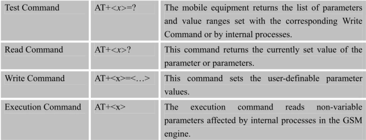
1.4.3 Extended Syntax
These commands can operate in several modes, as in the following table:
Table 1: Types of AT commands and responses
Test Command AT+<x>=? The mobile equipment returns the list of parameters
and value ranges set with the corresponding Write Command or by internal processes.
Read Command AT+<x>? This command returns the currently set value of the
parameter or parameters.
Write Command AT+<x>=<…> This command sets the user-definable parameter values.
Execution Command AT+<x> The execution command reads non-variable parameters affected by internal processes in the GSM engine.
1.4.4 Combining AT commands on the same Command line
You can enter several AT commands on the same line. In this case, you do not need to type the "AT" or "at" prefix before every command. Instead, you only need type "AT" or "at" the beginning of the command line. Please note to use a semicolon as the command delimiter after
an extended command; in basic syntax or S parameter syntax, the semicolon need not enter, for example: ATE1Q0S0=1S3=13V1X4;+IFC=0,0;+IPR=115200;&W.
The Command line buffer can accept a maximum of 556 characters (counted from the first command without “AT” or “at” prefix). If the characters entered exceeded this number then none of the Command will executed and TA will return "ERROR".
1.4.5 Entering successive AT commands on separate lines
When you need to enter a series of AT commands on separate lines, please Note that you need to wait the final response (for example OK, CME error, CMS error) of last AT Command you entered before you enter the next AT Command.
1.5 Supported character sets
The SIM800 Series AT Command interface defaults to the IRA character set. The SIM800 Series supports the following character sets:
GSM format UCS2 HEX IRA PCCP PCDN 8859-1
The character set can be set and interrogated using the "AT+CSCS" Command (3GPP TS 27.007). The character set is defined in GSM specification 3GPP TS 27.005.
The character set affects transmission and reception of SMS and SMS Cell Broadcast messages, the entry and display of phone book entries text field and SIM Application Toolkit alpha strings.
1.6 Flow control
Flow control is very important for correct communication between the GSM engine and DTE. For in the case such as a data or fax call, the sending device is transferring data faster than the receiving side is ready to accept. When the receiving buffer reaches its capacity, the receiving device should be capable to cause the sending device to pause until it catches up.
There are basically two approaches to achieve data flow control: software flow control and hardware flow control. SIM800 Series support both two kinds of flow control.
In Multiplex mode, it is recommended to use the hardware flow control.
1.6.1 Software flow control (XON/XOFF flow control)
Software flow control sends different characters to stop (XOFF, decimal 19) and resume (XON, decimal 17) data flow. It is quite useful in some applications that only use three wires on the serial interface.
The default flow control approach of SIM800 Series is hardware flow control (RTS/CTS flow control), to enable software flow control in the DTE interface and within GSM engine, type the following AT Command:
AT+IFC=1, 1
This setting is stored volatile, for use after restart, AT+IFC=1, 1 should be stored to the user profile with AT&W.
NOTE:
The AT commands listed in the table of AT&W chapter should be stored to user profile with
AT&W for use after restart. Most other AT commands in V.25, 3GPP TS 27.005, 3GPP TS
27.007,GPRS will store parameters automatically and can be used after module restart.
Ensure that any communications software package (e.g. Hyper terminal) uses software flow control.
NOTE:
Software Flow control should not be used for data calls where binary data will be transmitted or received (e.g. TCP/IP) as the DTE interface may interpret binary data as flow control characters.
1.6.2 Hardware flow control (RTS/CTS flow control)
Hardware flow control achieves the data flow control by controlling the RTS/CTS line. When the data transfer should be suspended, the CTS line is set inactive until the transfer from the receiving buffer has completed. When the receiving buffer is ok to receive more data, CTS goes active once again.
To achieve hardware flow control, ensure that the RTS/CTS lines are present on your application platform.
1.7 Definitions
1.7.1 Parameter Saving Mode
For the purposes of the present document, the following syntactical definitions apply:
z NO_SAVE: The parameter of the current AT command will be lost if module is rebooted or
current AT command doesn't have parameter.
z AUTO_SAVE: The parameter of the current AT command will be kept in NVRAM
automatically, and it won't be lost if module is rebooted.
z AT&W_SAVE: The parameter of the current AT command will be kept in NVRAM by
1.7.2 Max Response Time
Max response time is estimated maximum time to get response, the unit is seconds. "-" means this AT command doesn’t care the response time.
2 AT Commands According to V.25TER
These AT Commands are designed according to the ITU-T (International Telecommunication Union, Telecommunication sector) V.25ter document.
2.1 Overview of AT Commands According to V.25TER
Command Description
A/ Re-issues the last command given
ATA Answer an incoming call
ATD Mobile originated call to dial a number
ATD><N> Originate call to phone number in current memory
ATD><STR> Originate call to phone number in memory which corresponds to field <str>
ATDL Redial last telephone number used
ATE Set command echo mode
ATH Disconnect existing connection
ATI Display product identification information ATL Set monitor speaker loudness
ATM Set monitor speaker mode
+++ Switch from data mode or ppp online mode to command mode ATO Switch from command mode to data mode
ATP Select pulse dialling
ATQ Set result code presentation mode
ATS0 Set number of rings before automatically answering the call ATS3 Set command line termination character
ATS4 Set response formatting character ATS5 Set command line editing character ATS6 Pause before blind dialling
ATS7 Set number of seconds to wait for connection completion
ATS8 Set number of seconds to wait for comma dial modifier encountered in dial string of D command
ATS10 Set disconnect delay after indicating the absence of data carrier
ATT Select tone dialing
ATV TA response format
ATX Set connect result code format and monitor call progress ATZ Reset default configuration
AT&C Set DCD function mode AT&D Set DTR function mode
AT&F Factory defined configuration AT&V Display current configuration AT&W Store active profile
AT+GCAP Request complete TA capabilities list AT+GMI Request manufacturer identification AT+GMM Request TA model identification
AT+GMR Request TA revision identification of software release AT+GOI Request global object identification
AT+GSN Request TA serial number identification (IMEI) AT+ICF Set TE-TA control character framing
AT+IFC Set TE-TA local data flow control AT+IPR Set TE-TA fixed local rate AT+HVOIC Disconnect voice call only
2.2 Detailed Description of AT Commands According to V.25TER
2.2.1 A/ Re-issues the Last Command Given A/ Re-issues the Last Command Given Execution
Command A/
Response
Re-issues the previous Command
Reference V.25ter
Note
2.2.2 ATA Answer an Incoming Call ATA Answer an Incoming Call Execution
Command ATA
Response
TA sends off-hook to the remote station.
Note1: Any additional commands on the same Command line are ignored. Note2: This Command may be aborted generally by receiving a character during execution. The aborting is not possible during some states of connection establishment such as handshaking.
Response in case of data call, if successfully connected
CONNECT<text> TA switches to data mode.
Note: <text> output only if ATX<value> parameter setting with the <value>>0
When TA returns to Command mode after call release OK
OK Response if no connection NO CARRIER Parameter Saving Mode NO_SAVE Max Response Time 20s(voice call)
Timeout set with ATS7 (data call) Reference
V.25ter
Note
See also ATX
2.2.3 ATD Mobile Originated Call to Dial A Number ATD Mobile Originated Call to Dial A Number Execution
Command ATD<n>[<mgsm ][;]
Response
This Command can be used to set up outgoing voice, data or fax calls. It
also serves to control supplementary services.
Note: This Command may be aborted generally by receiving an ATH Command or a character during execution. The aborting is not possible during some states of connection establishment such as handshaking.
If error is related to ME functionality +CME ERROR: <err>
If no dial tone and (parameter setting ATX2 or ATX4) NO DIALTONE
If busy and (parameter setting ATX3 or ATX4) BUSY
If a connection cannot be established NO CARRIER
If the remote station does not answer NO ANSWER
If connection successful and non-voice call.
CONNECT<text> TA switches to data mode.
Note: <text> output only if ATX<value> parameter setting with the <value> >0
When TA returns to Command mode after call release OK
If connection successful and voice call OK
Parameters
<n> String of dialing digits and optionally V.25ter modifiers dialing digits:
0-9, * , #, +, A, B, C
Following V.25ter modifiers are ignored: ,(comma), T, P, !, W, @
Emergency call:
<n> Standardized emergency number 112 (no SIM needed)
<mgsm> String of GSM modifiers:
I Actives CLIR (Disables presentation of own number to called party)
i Deactivates CLIR (Enable presentation of own number to called party)
G Activates Closed User Group invocation for this call only
g Deactivates Closed User Group invocation for this call only
<;> Only required to set up voice call , return to Command state Parameter Saving Mode NO_SAVE Max Response Time 20s(voice call)
Timeout set with ATS7 (data call) Reference
V.25ter
Note
Parameter "I" and "i" only if no *# code is within the dial string
<n> is default for last number that can be dialed by ATDL
*# codes sent with ATDare treated as voice calls. Therefore, the Command must be terminated with a semicolon ";"
See ATX Command for setting result code and call monitoring parameters. Responses returned after dialing with ATD
For voice call two different responses mode can be determined. TA returns "OK" immediately either after dialing was completed or after the call is established. The setting is controlled by AT+COLP. Factory default is
AT+COLP=0, this cause the TA returns "OK" immediately after dialing
was completed, otherwise TA will returns "OK", "BUSY", "NO DIAL TONE", "NO CARRIER".
Using ATD during an active voice call:
voice call, the first call will be automatically put on hold.
The current states of all calls can be easily checked at any time by using the
AT+CLCC Command.
2.2.4 ATD><n> Originate Call to Phone Number in Current Memory ATD><n> Originate Call to Phone Number in Current Memory
Response
This Command can be used to dial a phone number from current phonebook memory.
Note: This Command may be aborted generally by receiving an ATH Command or a character during execution. The aborting is not possible during some states of connection establishment such as handshaking.
If error is related to ME functionality +CME ERROR: <err>
If no dial tone and (parameter setting ATX2 or ATX4)
NO DIALTONE
If busy and (parameter setting ATX3 or ATX4) BUSY
If a connection cannot be established NO CARRIER
If the remote station does not answer NO ANSWER
If connection successful and non-voice call.
CONNECT<text>TA switches to data mode.
Note: <text> output only if ATX<value> parameter setting with the <value> >0
When TA returns to Command mode after call release OK
If successfully connected and voice call OK Execution Command ATD><n>[<clir> ][<cug>][;] Parameters
<n> Integer type memory location should be in the range of locations
available in the memory used
<clir>
I Override the CLIR supplementary service subscription default value for this call
Invocation (restrict CLI presentation)
i Override the CLIR supplementary service subscription default value for this call
Suppression (allow CLI presentation) <cug>
G Control the CUG supplementary service information for this call
CUG Not supported
g Control the CUG supplementary service information for this call
CUG Not supported
<;> Only required to set up voice call , return to
Command state Parameter Saving Mode NO_SAVE Max Response Time - Reference V.25ter Note
Parameter "I" and "i" only if no *# code is within the dial string
*# codes sent with ATDare treated as voice calls. Therefore, the Command must be terminated with a semicolon ";"
See ATX Command for setting result code and call monitoring parameters.
2.2.5 ATD><str> Originate Call to Phone Number in Memory Which Corresponds to Field <str>
ATD><str> Originate Call to Phone Number in Memory Which Corresponds to Field <str> Execution Command ATD><str>[<clir >][<cug>][;] Response
This Command make the TA attempts to set up an outgoing call to stored number.
All available memories are searched for the entry <str>.
Note: This Command may be aborted generally by receiving an ATH Command or a character during execution. The aborting is not possible during some states of connection establishment such as handshaking.
If error is related to ME functionality +CME ERROR: <err>
If no dial tone and (parameter setting ATX2 or ATX4) NO DIALTONE
If busy and (parameter setting ATX3 or ATX4) BUSY
If a connection cannot be established NO CARRIER
If the remote station does not answer NO ANSWER
If connection successful and non-voice call.
CONNECT<text>TA switches to data mode.
Note: <text> output only if ATX<value> parameter setting with the <value> >0
When TA returns to Command mode after call release OK
If successfully connected and voice call OK
Parameters
<str> String type (string should be included in quotation marks) value
("x"), which should equal to an alphanumeric field in at least one phone book entry in the searched memories. str formatted as current TE character set specified by +CSCS.
<mgsm> String of GSM modifiers:
I Actives CLIR (Disables presentation of own number to called party)
i Deactivates CLIR (Enable presentation of own number to called party)
G Activates Closed User Group invocation for this call only
g Deactivates Closed User Group invocation for this call only
<;> Only required to set up voice call, return to Command state Parameter Saving Mode NO_SAVE Max Response Time - Reference V.25ter Note
Parameter "I" and "i" only if no "*#" code is within the dial string
*# codes sent with ATDare treated as voice calls. Therefore, the Command must be terminated with a semicolon ";"
See ATX Command for setting result code and call monitoring parameters.
2.2.6 ATDL Redial Last Telephone Number Used ATDL Redial Last Telephone Number Used Execution
Command ATDL
Response
This Command redials the last voice and data call number used.
Note: This Command may be aborted generally by receiving an ATH Command or a character during execution. The aborting is not possible during some states of connection establishment such as handshaking.
If error is related to ME functionality +CME ERROR: <err>
If no dial tone and (parameter setting ATX2 or ATX4)
NO DIALTONE
If busy and (parameter setting ATX3 or ATX4) BUSY
If a connection cannot be established NO CARRIER
If the remote station does not answer NO ANSWER
If connection successful and non-voice call.
CONNECT<text>TA switches to data mode.
Note: <text> output only if ATX<value> parameter setting with the <value> >0
When TA returns to Command mode after call release OK
If successfully connected and voice call OK Parameter Saving Mode NO_SAVE Max Response Time - Reference V.25ter Note
See ATX Command for setting result code and call monitoring parameters. Return the numbers and symbols which ATD supports if there is no last
dialing context.
2.2.7 ATE Set Command Echo Mode ATE Set Command Echo Mode
Response
This setting determines whether or not the TA echoes characters received from TE during Command state.
OK Execution
Command ATE<value>
Parameter
<value> 0 Echo mode off
1 Echo mode on Parameter Saving Mode AT&W_SAVE Max Response Time - Reference V.25ter Note
2.2.8 ATH Disconnect Existing Connection ATH Disconnect Existing Connection Execution
Command ATH
Response
Disconnect existing call by local TE from Command line and terminate call OK
Note: OK is issued after circuit 109(DCD) is turned off, if it was previously on. Parameter Saving Mode NO_SAVE Max Response Time 20s Reference V.25ter Note
2.2.9 ATI Display Product Identification Information ATI Display Product Identification Information Execution
Command ATI
Response
TA issues product information text Example:
OK Parameter Saving Mode NO_SAVE Max Response Time - Reference V.25ter Note
2.2.10 ATL Set Monitor speaker loudness ATL Set Monitor speaker loudness
Response OK Execution Command ATL<value> Parameter <value> 0..9 Volume Parameter Saving Mode NO_SAVE Max Response Time - Reference V.25ter Note No effect in GSM
2.2.11 ATM Set Monitor Speaker Mode ATM Set Monitor Speaker Mode
Response OK Execution Command ATM<value> Parameter <value> 0..9 Mode Parameter Saving Mode NO_SAVE Max Response Time - Reference V.25ter Note No effect in GSM
2.2.12 +++ Switch from Data Mode or PPP Online Mode to Command Mode
+++ Switch from Data Mode or PPP Online Mode to Command Mode
Execution Command +++
Response
The +++ character sequence causes the TA to cancel the data flow over the AT interface and switch to Command mode. This allows you to enter AT Command while maintaining the data connection to the remote server.
OK
To prevent the +++ escape sequence from being misinterpreted as data, it should comply to following sequence:
No characters entered for T1 time (1 second)
"+++" characters entered with no characters in between (1 second) No characters entered for T1 timer (1 second)
Switch to Command mode, otherwise go to step 1. Parameter Saving Mode NO_SAVE Max Response Time - Reference V.25ter Note
To return from Command mode back to data mode: Enter ATO.
2.2.13 ATO Switch from Command Mode to Data Mode ATO Switch from Command Mode to Data Mode
Response
TA resumes the connection and switches back from Command mode to data mode.
CONNECT
If connection is not successfully resumed ERROR
else
TA returns to data mode from command mode CONNECT<text> Note: <text> only if parameter setting ATX>0
Execution Command ATO[n]
Parameter
<n> 0 Switch from command mode to data mode.
Parameter Saving Mode NO_SAVE Max Response Time - Reference V.25ter Note
2.2.14 ATP Select Pulse Dialling ATP Select Pulse Dialling
Execution Command ATP Response OK Parameter Saving Mode NO_SAVE Max Response Time - Reference V.25ter Note No effect in GSM
2.2.15 ATQ Set Result Code Presentation Mode ATQ Set Result Code Presentation Mode
Response
This parameter setting determines whether or not the TA transmits any result code to the TE. Information text transmitted in response is not affected by this setting. If <n>=0: OK If <n>=1: (none) Execution Command ATQ<n> Parameter
<n> 0 TA transmits result code
1 Result codes are suppressed and not transmitted Parameter Saving Mode AT&W_SAVE Max Response Time - Reference V.25ter Note
2.2.16 ATS0 Set Number of Rings before Automatically Answering the Call ATS0 Set Number of Rings before Automatically Answering the Call
Response <n> OK Read Command ATS0? Parameter
See Write Command Write Command
ATS0=<n>
Response
This parameter setting determines the number of rings before auto-answer. OK
ERROR Parameter
<n> 0 Automatic answering is disable.
1-255 Number of rings the modem will wait for before answering the phone if a ring is detected.
Parameter Saving Mode AT&W_SAVE Max Response Time - Reference V.25ter Note
If <n>is set too high, the calling party may hang up before the call can be answered automatically.
2.2.17 ATS3 Set Command Line Termination Character ATS3 Set Command Line Termination Character
Response <n> OK Read Command ATS3? Parameter
See Write Command Response
This parameter setting determines the character recognized by TA to terminate an incoming Command line. The TA also returns this character in output. OK ERROR Write Command ATS3=<n> Parameter
<n> 13 Command line termination character
Parameter Saving Mode AT&W_SAVE Max Response Time - Reference V.25ter Note
Default 13 = CR. It only supports default value.
2.2.18 ATS4 Set Response Formatting Character ATS4 Set Response Formatting Character Read Command Response
<n>
OK ATS4?
Parameter
See Write Command Response
This parameter setting determines the character generated by the TA for result code and information text.
OK
ERROR Write Command
ATS4=<n>
Parameter
<n> 10 Response formatting character Parameter Saving Mode AT&W_SAVE Max Response Time - Reference V.25ter Note
Default 10 = LF. It only supports default value.
2.2.19 ATS5 Set Command Line Editing Character ATS5 Set Command Line Editing Character
Response <n> OK Read Command ATS5? Parameter
See Write Command Response
This parameter setting determines the character recognized by TA as a request to delete from the Command line the immediately preceding character. OK ERROR Write Command ATS5=<n> Parameter
<n> 0-8-127 Response formatting character
Parameter Saving Mode
AT&W_SAVE Max Response -
Time Reference V.25ter
Note
Default 8 = Backspace.
2.2.20 ATS6 Pause Before Blind Dialling ATS6 Pause Before Blind Dialling Read Command ATS6? Response <n> OK Response OK ERROR Write Command ATS6=<n> Parameter <n> 0..999 Time Parameter Saving Mode AT&W_SAVE Max Response Time - Reference V.25ter Note No effect in GSM
2.2.21 ATS7 Set Number of Seconds to Wait for Connection Completion ATS7 Set Number of Seconds to Wait for Connection Completion
Response <n> OK Read Command ATS7? Parameter
See Write Command Response
This parameter setting determines the amount of time to wait for the connection completion in case of answering or originating a call. OK
ERROR Write Command
ATS7=<n>
Parameter
<n> 1-60-255 Number of seconds to wait for connection completion
Parameter Saving Mode
Max Response Time - Reference V.25ter Note
If called party has specified a high value for ATS0=<n>, call setup may fail. The correlation between ATS7 and ATS0 is important
Example: Call may fail if ATS7=30 and ATS0=20. ATS7 is only applicable to data call.
2.2.22 ATS8 Set Number of Seconds to Wait for Comma Dial Modifier Encountered in Dial String of D Command
ATS8 Set Number of Seconds to Wait for Comma Dial Modifier Encountered in Dial String of D Command Response <n> OK Read Command ATS8? Parameter
See Write Command Response OK ERROR Write Command ATS8=<n> Parameter
<n> 0-255 The value of this register determines how long the modem
should pause when it sees a comma in the dialing string. Parameter Saving Mode AT&W_SAVE Max Response Time - Reference V.25ter Note No effect in GSM
2.2.23 ATS10 Set Disconnect Delay after Indicating the Absence of Data Carrier ATS10 Set Disconnect Delay after Indicating the Absence of Data Carrier
Response <n> OK Read Command ATS10? Parameter
See Write Command Write Command
ATS10=<n>
Response
remain connected in absence of data carrier. If the data carrier is once more detected before disconnecting, the TA remains connected.
OK
ERROR Parameter
<n> 1-15-254 Number of tenths seconds of delay
Parameter Saving Mode AT&W_SAVE Max Response Time - Reference V.25ter Note
2.2.24 ATT Select Tone Dialing ATT Select Tone Dialing Execution Command ATT Response OK Parameter Saving Mode AUTO_SAVE Max Response Time - Reference V.25ter Note
2.2.25 ATV TA Response Format ATV TA Response Format
Response
This parameter setting determines the contents of the header and trailer transmitted with result codes and information responses.
When<value>=0 0 When<value>=1 OK Execution Command ATV<value> Parameter
<value> 0 Information response: <text><CR><LF> Short result code format: <numeric code><CR> 1 Information response: <CR><LF><text><CR><LF>
Long result code format: <CR><LF><verbose code> <CR><LF>
The result codes, their numeric equivalents and brief descriptions of the use of each are listed in the following table.
Parameter Saving Mode AT&W_SAVE Max Response Time - Reference V.25ter Note
ATV1 ATV0 Description
OK 0 Acknowledges execution of a Command
CONNECT 1 A connection has been established; the DCE is moving from Command state to online data state
RING 2 The DCE has detected an incoming call signal from
network
NO CARRIER 3 The connection has been terminated or the attempt to establish a connection failed
ERROR 4 Command not recognized, Command line maximum length
exceeded, parameter value invalid, or other problem with processing the Command line
NO DIALTONE 6 No dial tone detected
BUSY 7 Engaged (busy) signal detected
NO ANSWER 8 "@" (Wait for Quiet Answer) dial modifier was used, but remote ringing followed by five seconds of silence was not detected before expiration of the connection timer (S7) PROCEEDING 9 An AT command is being processed
CONNECT <text>
Manufacturer- specific
Same as CONNECT, but includes manufacturer-specific text that may specify DTE speed, line speed, error control, data compression, or other status
2.2.26 ATX Set CONNECT Result Code Format and Monitor Call Progress ATX Set CONNECT Result Code Format and Monitor Call Progress
Response
This parameter setting determines whether or not the TA detected the presence of dial tone and busy signal and whether or not TA transmits particular result codes.
OK ERROR Execution Command ATX<value> Parameter
detection are both disabled.
1 CONNECT<text> result code only returned, dial tone and
busy detection are both disabled.
2 CONNECT<text> result code returned, dial tone
detection is enabled, busy detection is disabled.
3 CONNECT<text> result code returned, dial tone
detection is disabled, busy detection is enabled.
4 CONNECT<text> result code returned, dial tone and
busy detection are both enabled. Parameter Saving Mode AT&W_SAVE Max Response Time - Reference V.25ter Note
2.2.27 ATZ Reset Default Configuration ATZ Reset Default Configuration
Response
TA sets all current parameters to the user defined profile. OK ERROR Execution Command ATZ[<value>] Parameter
<value> 0 Restore profile 0 Parameter Saving Mode NO_SAVE Max Response Time - Reference V.25ter Note
Parameter impacted by Z command: refer to AT&W
NOTE:
[SIM800H] Parameters related to uart operation, like ipr, icf, ifc and cmnrp, will not be reset to default configuration.
2.2.28 AT&C Set DCD Function Mode AT&C Set DCD Function Mode Execution
Command AT&C<value>
Response
This parameter determines how the state of circuit 109 (DCD) relates to the detection of received line signal from the distant end.
OK
ERROR Parameter
<value> 0 DCD line is always ON
1 DCDline is ON only in the presence of data carrier Parameter Saving Mode AT&W_SAVE Max Response Time - Reference V.25ter Note
2.2.29 AT&D Set DTR Function Mode AT&D Set DTR Function Mode
Response
This parameter determines how the TA responds when circuit 108/2 (DTR) is changed from the ON to the OFF condition during data mode.
OK ERROR Execution Command AT&D[<value>] Parameter
<value> 0 TA ignores status on DTR.
1 ON->OFF on DTR: Change to Command mode with remaining the connected call.
2 ON->OFF on DTR: Disconnect call, change to Command mode. During state DTR = OFF is auto-answer off.
Parameter Saving Mode AT&W_SAVE Max Response Time - Reference V.25ter Note
2.2.30 AT&F Factory Defined Configuration AT&F Factory Defined Configuration
Response
TA sets all current parameters to the manufacturer defined profile. OK
Execution Command AT&F[<value>]
Parameter
Parameter Saving Mode NO_SAVE Max Response Time - Reference V.25ter Note
Parameter impacted by &F command: refer to AT&W
NOTE:
[SIM800H] Parameters related to uart operation, like ipr, icf, ifc and cmnrp, will not be reset to default configuration.
2.2.31 AT&V Display Current Configuration AT&V Display Current Configuration
Response
TA returns the current parameter setting. <current configurations text>
OK ERROR Execution Command AT&V[<n>] Parameter
<n> 0 Responses in numeric format
Parameter Saving Mode NO_SAVE Max Response Time - Reference V.25ter Note
2.2.32 AT&W Store Active Profile AT&W Store Active Profile
Response
TA stores the current parameter setting in the user defined profile. OK ERROR Execution Command AT&W[<n>] Parameter
<n> 0 Store the current configuration in profile 0
Parameter Saving Mode NO_SAVE Max Response Time -
Reference V.25ter
Note
The user defined profile is stored in non volatile memory.
Parameter stored by &W
Command Parameter name Displayedby &V
ATS0 <num> Y ATS3 <char> Y ATS4 <char> Y ATS5 <char> Y ATS6 <short> Y ATS7 <time> Y ATS8 <time> Y ATS10 <time> Y AT+CBST <speed>,<name>,<ce> Y AT+CRLP <iws>,<mws>,<T1>,<N2> Y ATV <format> Y ATE <echo> Y ATQ <result> Y ATX <result> Y AT&C <behavior> Y AT&D <behavior> Y AT+CLTS <timestamp> Y AT+CREG <n> Y AT+CGREG <n> Y AT+CMEE <n> Y AT+CSCLK <n> Y AT+CIURC <mode> Y AT+CFGRI <mode> Y AT+CMTE <mode> Y AT+CANT <mode>,<UrcEnable>,<timer> Y AT+STKPCIS <switch> Y AT+CMGF <mode> Y AT+CNMI <mode>,<mt>,<bm>,<ds>,<bfr> Y AT+CSCS <chest> Y AT+VTD <n> Y AT+CALS <n> Y AT+CHF <ind> Y AT+CAAS <mode> Y AT+CBUZZERRING <mode> Y
AT+DDET <n> Y AT+MORING <mode> Y AT+SVR <voice_rate_coding> Y AT+CCPD <mode> Y AT+CSGS <mode> Y AT+CNETLIGHT <mode> Y AT+SLEDS <mode>,<timer_on>,<timer_off> Y AT+CSDT <mode> Y AT+CSMINS <n> Y AT+EXUNSOL <exunsol> Y AT+IPR <n> Y
AT+IFC <TA_by_TE>, <TE_by_TA> Y AT+ICF <format>,<parity> Y
AT+SD2PCM <mode> Y
NOTE: