Santa Clara University
Scholar Commons
Interdisciplinary Design Senior Theses Engineering Senior Theses
6-2018
Pressure Ulcer Prevention System
Rey-David Palomares
Santa Clara University, [email protected]
Ojus Rao
Santa Clara University, [email protected]
Follow this and additional works at:https://scholarcommons.scu.edu/idp_senior
Part of theComputer Engineering Commons, and theElectrical and Computer Engineering Commons
This Thesis is brought to you for free and open access by the Engineering Senior Theses at Scholar Commons. It has been accepted for inclusion in Interdisciplinary Design Senior Theses by an authorized administrator of Scholar Commons. For more information, please [email protected].
Recommended Citation
Palomares, Rey-David and Rao, Ojus, "Pressure Ulcer Prevention System" (2018).Interdisciplinary Design Senior Theses. 42. https://scholarcommons.scu.edu/idp_senior/42
PRESSURE ULCER PREVENTION SYSTEM
By
Rey-David Palomares, Ojus Rao
SENIOR DESIGN PROJECT REPORT
Submitted to
the Department of Computer Science and Engineering, Electrical Engineering of
SANTA CLARA UNIVERSITY in Partial Fulfillment of the Requirements
for the degrees of
Bachelor of Science in Computer Science and Engineering, Electrical Engineering Santa Clara, California
Abstract
Pressure ulcers, also known as bedsores, are a widespread but often understated problem. A pressure ulcer is an injury that develops with constant pressure on an area of skin for a long time. They range from bruises to open wounds to even exposed bone. These injuries especially impact bedridden and elderly hospital inpatients, since these people must depend on nursing staff for mobility. Pressure ulcers can seem to be a solved problem. Solutions that completely eliminate pressure ulcers do exist. These solutions, however, are too expensive for widespread use, at thousands of dollars per bed. Other solutions, such as relying on nursing staff to move all patients is not reliable, and nurses develop chronic back pain from the strain of moving so many patients so often.
The Pressure Ulcer Prevention System is designed specifically to be an affordable solution for these injuries in a hospital or assisted living setting. The system collects data from a gyroscopic sensor and multiple pressure sensors mounted on the patient, and sends an alert to the nurses’ station if a patient is at risk of developing a pressure ulcer, and needs attending. The system does not replace nurse care, nor does it change the most common solution of manually moving patients, but it instead helps nursing staff be more efficient.
Acknowledgments
Both team members, Rey and Ojus, would really like to thank everyone who helped further our knowledge on our project’s subject matter and enabled us to make our project. Specifically we would like to thank our advisors Professor Dan Lewis in the Computer Engineering Department and Professor Sally Wood in the Electrical Engineering Department. Their assistance and advice has been very helpful throughout the project from its conception to the final reveal. We would also like to thank the Engineering Department for understanding the potential in our project and awarding us with a grant. Finally we would also like to give a special thanks to our family members for introducing the idea behind our project and supporting us emotionally.
Table of Contents
Abstract 1
Acknowledgments 2
Table of Contents 3
List of Figures and List of Tables 4
1 Introduction 6
1.1 Problem Statement: 6
1.2 Related Work: 6
3 Objectives: 8
Objectives for the patient side: 8
Objectives for the server side: 8
2 Project Requirements 10 2.1 Functional Requirements 10 2.2 Non-functional Requirements 10 2.3 Design Constraints 10 3 Design Process 11 3.1 Early Design: 11 3.2 On Body: 13 3.3 Velcro Shirt: 15
3.4 Communication Over Wifi 16
3.5 Notification System 17 3.6 Proof of Concept 18 4 Alternatives Considered 19 4.1 Collecting Data 19 4.2 Processing Data 20 4.3 Response 20 5 Business Case 22 6 Use Cases 23
6.3 View Sleep Records 24 7 Activity Diagrams 25 8 Model 27 8.1 Hardware 27 8.2 Software 28 10 Block Diagrams 31 10.1 Overarching Diagram 31 10 Testing 32 10.1 Software 32 10.2 Hardware 32 11 Societal Issues 34 11. Compassion 44 12 Conclusions 46 12.1 What we learned 46 12.2 Setbacks 46 12.3 Future Developments 46 13 References 48 14 Appendices 50
Appendix A: Web Technologies Used 50
Appendix B: Proof of Concept Graphs - FSR 51
Appendix C: Proof of Concept Graphs - Gyroscopic Module 53
Appendix D: Proof of Concept - FSR Code 54
List of Figures and List of Tables
Figure 1: FSR (Source: AliExpress) Figure 2: FSR Voltage Divider Eqn 1: Voltage Drop over FSR
Figure 3: Pedobarography (Source: Wikimedia Commons) Figure 4: Gyroscopic Sensor Module (Source: Sparkfun) Eqn 2: Integral for Angular Position
Eqn:3 Approximation of Integral for Angular Position Figure 5: Chest Band Design
Figure 6: Velcro Shirt Design Figure 7: Raspberry Pi 3 Figure 8: Arduino Mega 2560
Table 1: Data Communication Order
Figure 9: Patient-Side Proof of Concept Model Figure 10: Use Case Figure
Figure 11: General Usage Diagram Figure 12: Caregiver Activity Diagram Figure 13: Mounting Shirt
Figure 14: Gyroscope (Source: SparkFun) Figure 15: Arduino(source Arduino) Figure 16: Login
Figure 17: Patient Data on Homepage
Figure 18: Color Coded Pressure on the Body Figure 19: Block Diagram
Figure 20: Sensors and Arduino 11 11 12 12 13 14 14 14 15 16 16 17 19 24 26 27 28 28 28 29 30 31 32 33
1 Introduction
1.1 Problem Statement:
The sponsor desires that a system be developed to prevent pressure ulcers in a hospital setting, subject to the following criteria:
1. The system must allow normal hospital operation and reasonable freedom of movement. It is reasonable to assume that the patients most at risk of pressure ulcers do not have much freedom of movement, but the system should still be usable and reasonably comfortable for all inpatients to wear.
2. The system must not interrupt normal patient sleep. Sleep is critical for good health, and a patient with better sleep does better overall than otherwise. Also, sleeping hours are critical for pressure ulcer prevention, since people cannot consciously move themselves while they sleep, and infirm or elderly people may not move themselves at all. It is vital that the system be operational during a patient’s sleep.
3. The system must be relatively inexpensive. Solutions which completely prevent pressure ulcers already exist, but are very expensive. This system will target the market of
low-cost monitoring devices, but with better precision and more robust data than is currently available.
4. The system must be able to quickly alert nursing staff to potential pressure ulcers. Systems which physically move the patient or alter pressure under the patient already exist, and they are very expensive. This system will serve a less expensive market by relying on nursing staff to manually move patients. The added benefit will come from efficiency, since the system will alert nurses to only move those patients which need to be moved.
5. The system must be noninvasive. Health and safety concerns increase exponentially with invasive systems and treatments. Especially since there is no biomedical or
1.2 Related Work:
The problem of pressure ulcers is hardly a new one, and many solution variations exist. As mentioned in the criteria above, there exist systems which can completely prevent pressure ulcers by mechanically changing the patients pressure distribution. However, these are very expensive. A single air bladder pressure adjustment system from the popular medical device brand Arjo Huntleigh can cost $7.5k1.
Mattress replacement systems are currently the most thorough unmanned methods of preventing pressure ulcers. When they are not automated, like the air bladder system mentioned above, then they are specially designed mattresses which help distribute pressure over the length of the body, so the time it takes to develop a pressure ulcer is extended.
Another common mitigation device is the pressure ulcer prevention pad, which resemble large padded adhesive bandages. These pads work in the same way as non-automated mattress replacements, and distribute pressure across the pad. These pads are applied by medical personnel on risk areas. Because these pads come into direct contact with the patient, they are designed to be disposable.9
Discrete prevention systems, like the preventions pads work because pressure ulcer incidence is well recorded, so critical risk areas have been identified. These areas include the back of the head, the shoulder blades, the tailbone, the rib cage, and joints such as the hips, elbows, and ankles.10
The design for the Pressure Ulcer Prevention System is based on the idea of patient detection and caregiver alerts, which is also not a new system. Hospital beds are often fitted with weight sensors which can detect if a patient has left the bed. Other systems include infrared beams around the edges of the hospital bed, which can detect if a patient is reaching over or traveling over the railing. For at-home use, large pads, similar in size to a placemat, are placed under the pelvic region, and trigger an alarm sound. Early designs for the Pressure Ulcer Prevention System were inspired by such bed-sensing techniques.
Further inspiration was drawn from a 2017 senior design project, the ForSpotter project from students Oliver Jakobi and Randy Louie. The ForSpotter used an array of pressure sensors under a wooden board, on which the user would stand. The ForSpotter would be able to take pressure measurements of the user’s weight distribution, and visually show the user how to adjust their center of gravity to be correctly balanced over their own feet. The exact sensors used in the
Early iterations of the final design, a wearable device, were inspired by chest strap heart rate monitors. These monitors are lightweight, wireless devices which transmit data over wifi or bluetooth to a partner device, typically a cellphone or smart watch. Some of these devices already on the market also include accelerometers used as pedometers.
3 Objectives:
The project quickly split into two separate sub-projects. One was the patient side, which would collect data from the patients physical inputs on the sensors, and the other was the remote alert side, which would process send alerts to the nurses, and display data in an easy-to-understand form.
Objectives for the patient side:
1. Select sensors which can collect data about a patient’s orientation and/or position within their hospital bed.
2. Select a processing unit which can go mounted on the patient’s body. This processing unit must be able to take input from the sensors, and transmit data wirelessly.
3. With the sensors selected, collect any data from the sensors, even if it is not yet meaningful. Ensure that the processing unit is getting repeatable results.
4. Design preliminary data analysis/aggregation algorithm to run on the processing unit. 5. Design file format for information transfer to the server-side.
6. Set up communication with server side.
7. Send values collected from sensors using known values from weights and specified movements
Objectives for the server side:
1. Design a data table to store values in a database.
2. Decide valid user action / normal operation through the program 3. Design user interface
4. Determine required web technologies
5. Create and populate data table with test values
6. Implement pressure ulcer prevention algorithm, and run with test values 7. Create web app front end and connect with database back end
8. Set up communication between patient-side and server-side
9. Test pressure ulcer prevention algorithm with data from patient-side 10. Improve pressure ulcer detection algorithm.
2 Project Requirements
2.1 Functional Requirements
The system will:
● Provide a method to monitor patients continuously with less effort ● Help identify areas on the patient’s body which have had long term
pressure applied to them
● Provide reminders and alerts to notify caregivers when it’s time to adjust the patient
● Have an easy-to-understand interface so caregivers can locate a patient’s information quickly
2.2 Non-functional Requirements
The system will:
● Quiet enough to not disturb sleep (< 40 dB) ● Able to support most adult’s weight (100-200 lb)
● Responsive to changes in body position if patients move
2.3 Design Constraints
The system will:
● Be non-invasive so to allow a patient movement ● Cheap (less than the current solutions on the market) ● Have minimal on-body contact with the patient ● Fit on a standard twin-size bed
3 Design Process
3.1 Early Design:
Few changes were made to the plans for the web server during the course of this project. It was always the intention that the web server would send notifications through a web app, and that the data would be displayed visually on a graphical representation of the patient’s body.
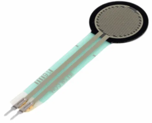
The major changes came in hardware. The earliest approach to sensor placement focused on not disrupting the patient or requiring daily application by nursing staff. This would be done by putting pressure sensors on the surface of the mattress, under the bedding. These sensors would be force sensitive resistors (FSRs), and change resistance based on how compressed they are.
Figure 1: FSR (Source: AliExpress)2
They range from completely uncompressed at 0kg and 100kΩ to the upper weight bound at 2kg and 10kΩ. By using a basic voltage divider circuit, it would be possible to measure the resistance because the voltage drop over a resistor in series is proportional to the resistance.
The analogue-digital converter would output the numerator of a fraction of 5V (realistically closer to 4.8V), with a denominator of 1024. Therefore, the voltage drop could be computed as:
Voltage_Drop = (ADC_Out / 1024) × 5V [Eqn 1]
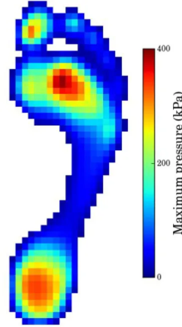
The data from the FSRs can be described similarly to pixels from a digital grayscale photo; each sensor has a location in a grid, and an intensity in a single dimension. The result is a planar view of things in contact with the mattress. A current commercial example would be pedobarography, which visually displays the pressure on the sole of the foot.
Figure 3: Pedobarography (Source: Wikimedia Commons)
The idea was to use image-processing and machine learning to analyze the data and interpret it as a person’s position and movements on the bed. Unfortunately, this was an unreasonable goal for this project. First was the material cost; a conservative estimate showed that the sensors alone for one bed would cost $700, and there was no good way to scale down for a proof of concept because of the resolution needed. Second was the scope of the programming. At the time when we began this project, we had no machine learning experience, and image processing seemed beyond reach during the timespan of the project. Lastly was the amount of data that would be necessary for machine learning; it would take multiple devices collecting data from a sleep lab, and multiple people manually combing through the data to set parameters for potential pressure ulcers.
Another problem arose, which was that even with machine learning, we did not feel that there would be enough confidence of a patient’s orientation in bed. The FSR behavior is highly non-linear, so accurate readings would be difficult to obtain. A patient could turn while mostly maintaining seemingly stable pressure on the sensors, and therefore we would not detect
movement. The compensation would result in a high rate of false positives, which would negate any added efficiency in nurse response that justified the system.
3.2 On Body:
The new goal was to be able to clearly detect a patient’s orientation in bed. The resulting course was to instead put sensors on the patient’s body. These sensors would be able to detect if that part of the patient’s body was in contact with the bed.
The search began for push buttons or switches that could work, but we did not find any with a thin enough profile to not be disruptive to patient comfort. Therefore, we returned to the FSRs, which have a nominal thickness of 0.46mm, comparable to a sheet of extra heavyweight paper. With minimal padding, a patient should be able to easily ignore the force sensitive resistors. Unlike in the bed mounting, these sensors would be compared against a threshold, so the resulting values would be interpreted as a on/off switch. The code for the voltage-divider processing can be found in Appendix D.
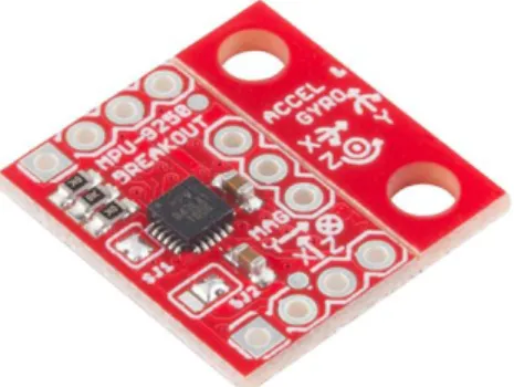
However, coverage was still an issue. In order to reduce costs, two decisions were made. First, FSRs would only go on high-risk areas, as mentioned with pressure ulcer prevention pads. Second, to supplement the FSRs and make the data collected more thorough, a gyroscopic sensor would be mounted on the patient’s chest.
The gyroscopic unit output angular velocity in three axes. Because the analysis to determine pressure ulcer risk works on angular position, it was necessary to take the integral of angular velocity.
θ = ∫ ω dt [Eqn 2]
However, for computing efficiency and not attempting a continuous integral with discrete values, an approximation of an integral was used instead.
θi+1 = θi + ω Δt [Eqn 3]
The processing unit communicated with the gyroscopic module using a two-wire I2C interface, with a baud rate of 400 kHz. The three values are transferred and stored as 16-bit integers. The code for this communication can be found in Appendix E.
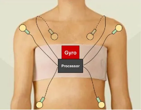
At this point, the device design was a gyroscopic sensor and a processing unit (a Raspberry Pi at this point) on a chest strap, with wires running to the FSRs adhesively attached to the patient. In order to distribute the pressure, the chest strap was not in as thin as heart rate monitors. Instead, the design used a gynecomastia chest band
The problems with this design are the same as with pressure ulcer prevention pads: it is
nurse-intensive, and application is time-consuming. Not only that, but the sensors would come into direct contact with the patient’s skin, which would explicitly go against the set objectives.
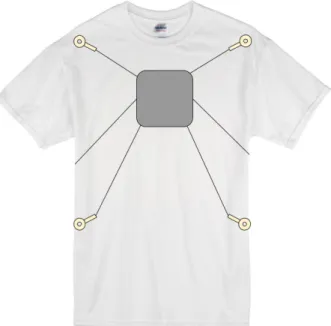
3.3 Velcro Shirt:
To solve the problems of the chest band design, the mounting garment was switched to a t-shirt. In order to make it easy for patients to get in and out of, the shirt would open in the back similar to a hospital gown, and would be fastened with a hook-and-loop system (commonly known by the brand name Velcro). The basic design would still use the single gyroscopic sensor on the chest, alongside the processing unit. Seven FSRs would be mounted at the critical areas: shoulders, shoulder blades, hips, and tailbone.
Figure 6: Velcro Shirt Design
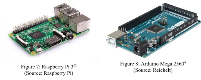
The selected processing unit at this point in the design was the single-board computer Raspberry Pi 3 Model B, which has built-in wifi and bluetooth capabilities. The drawback to this processing unit is the need for an external ADC. A reevaluation of the computing needs also determined that the Pi would not be fully utilized. The microcontroller unit board Arduino Mega 2560, which has a built-in ADC but not wifi, was used instead. (In reality, the functionally identical Keyestudio Mega 2560 was used.)
Figure 7: Raspberry Pi 312
(Source: Raspberry Pi)
Figure 8: Arduino Mega 25604
(Source: Reichelt)
In order to filter out momentary errors in the readings, each recorded value is actually the
average of ten values. For the binary processing of the FSRs, the average would be rounded with a threshold of 0.5.
3.4 Communication Over Wifi
The patient-side existed to collect and aggregate data, and the server side would analyze the data over a period of time. The default analysis period is two hours, to reflect current hospital
standards of moving patients every two hours. Communication between the two would happen over wifi once every ten minutes.
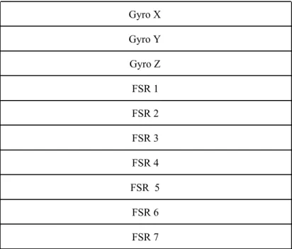
The format for sending the data is as separate requests, one per value. The order of values is first the three calculated values for gyroscopic position, followed by the on-off values of the FSRs.
Table 1: Data Communication Order Gyro X Gyro Y Gyro Z FSR 1 FSR 2 FSR 3 FSR 4 FSR 5 FSR 6 FSR 7
This format allows for easy expansion to more FSRs, which is also simple with the chosen hardware because the Arduino Mega 2560 has fifteen analogue inputs, and only seven are being used with the current set up.
3.5 Notification System
The server side of the project is responsible for collecting data, storing it in a database, and analyzing the risk that a patient develops a pressure ulcer. If the algorithm determines that a patient needs to be moved to reliably prevent a pressure ulcer, then the web app sends a notification. This system is intended to run at the nurses’ station.
The web application and database was hosted on the Santa Clara University server, therefore the server hardware did not change during project development.
The initial plan was to use machine learning to determine which readings corresponded to pressure ulcers. Unfortunately, no data set existed for this kind of thing, and creating one by hand seemed beyond reasonable for the time frame of the project. Therefore, the standard for a probable pressure ulcer was changed to reflect a general lack of movement over a long period of time.
For testing purposes, the very first algorithm implemented was a simple two-hour timer. This would send a notification every two hours unless it is manually reset from the web application. The second algorithm, the first one which used the data from the patient-side, was a two-hour timer per sensor that would reset whenever the sensor reading changed in such a way that indicated movement.
The problem with the second algorithm is that a patient could conceivably shift from one set of FSRs to another briefly before moving back. The result is that, although the timer would have reset, the patient was still on those areas of the body continuously enough to still be at risk of developing a pressure ulcer.
The third algorithm addressed that problem by setting the alert on a certain percentage of on-time per two-hour period. For example, if FSR 1 read as “on” for 90% of the last two hour period, then an alert would be sent that the patient needed to be moved off of that body part.
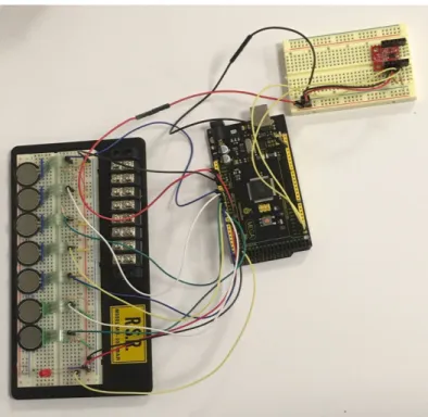
3.6 Proof of Concept
The demo constructed for the patient front end was the arduino board connected to two
solderless breadboards. One breadboard had the seven FSR voltage dividers and an LED which would turn on if a notification needed to be sent. The second breadboard had the gyroscopic sensor, complete with pull-up resistors for the I2C interface.
Figure 9: Patient-Side Proof of Concept Model
4 Alternatives Considered
As for the alternatives that we considered, and why they have not been selected.
The section will be broken up into the three major sections: collecting data, processing data, and responding to the data.
4.1 Collecting Data
For collecting data, we initially planned on using pressure sensors alone. Other options we looked at were load sensors and cameras. We considered each independently, and none quite stood up to the task alone.
Pressure sensors alone are not terribly useful. They are only accurate up to roughly 2 kg, meaning that for a person they would only serve as locations pressure is being applied, but not amount. Their structure also makes them unreliable on a curved surface, so using them on a person would not help much, and putting them on the bed possibly returned no useful information; it is conceivable that a person could shift on that array without changing their pressure distribution on the bed. In other words, this system would have a high rate of false alarms. The resolution needed to detect anything would be so high that, at $7 each, the the total cost would be prohibitive.
A gyroscope alone also provided little information. It is the simplest in terms of detecting a pressure ulcer --- if a person moves, then the gyroscope would pick it up --- but there are many systems on the market which can already do as much, and the goal of the project is to offer more than current systems already do. A gyroscope module is inexpensive, only around $15 each, which is why it is part of the final design.
Load sensors are slightly more useful than pressure sensors --- for $15 one can buy a sensor accurate up to 50 kg --- so they should be more sensitive than pressure sensors because they could pick up a person shifting in place.
Lastly, the team considered using cameras and image recognition/analysis to visually recognize patient movement. This option seemed interesting because cameras are nearly everywhere; if the system could work with any camera, then it could be implemented as quickly as the software can be distributed. The problem is that it seemed out of the scope of senior design, mostly because no member of the team had any working knowledge of image recognition/analysis.
In the end, the decision for the gyroscope was based on the idea that it is easy to determine if the patient has moved, and to use the pressure sensors to determine what region of the patient's body is at risk of developing pressure ulcers.
4.2 Processing Data
The modules considered for processing data were straightforward and comparable. The team looked at FPGAs, microcontroller boards (MCU), and single-board computers (SBC).
The FPGA boards bring along with them incredible numbers of inputs and outputs, along with immense processing speeds. However, the price range is proportionally high. The FPGA board used for comparison, the Mojo Development Board, cost $80. Other boards are in the hundreds. The two benefits of an FPGA board are also not relevant to the project; the high speed is
completely unnecessary for a system that is going to scan once every few minutes, and the number of inputs is not immediately helpful because any board within the team's price range does not take analog inputs --- which are needed for the pressure sensors.
The single-board computer considered was the Raspberry Pi 3. It is an inexpensive board, only $35 dollars, and has all functions of a simple computer. The main benefits were the ability to program in a language of choice, the built-in wifi and bluetooth capabilities, and the fact that one of the team members had previous experience with them. However, the inputs are all digital, meaning an additional ADC module would be required.
The microcontroller board that was referenced was the Arduino Zero, which costs around $45. The big benefit of the Arduino is that it has analog inputs an a built-in ADC. It would be necessary to buy an additional wifi or bluetooth module, which would add an extra $10 to the cost. As the team is in possession of an Arduino Uno the team ended up using it for testing purposes.
4.3 Response
The response must result in the Patient being adjusted, and the Caregiver being notified. The options we had considered were alternating air bladders, noise disturbance, electrical stimulation, wirelessly sending a message to the Caregiver, and wiring a connection to something like a nurses' station and sending the notifications there.
Noise disturbance, in principle, involves playing a noise to raise the Patient from REM sleep to deep sleep to light sleep, where the Patient would then move on their own. The trouble is that it would be necessary for the Caregiver to calibrate the system per Patient. In addition, the
response would likely not work in situations with multiple patients per room.
Electrical stimulation has multiple problems with it. Like noise disturbance, the system would need to be carefully calibrated per Patient. Unlike noise disturbance, the threshold between sensation and pain is extremely fine with electrical stimulation. For that reason alone, the team dropped the idea of electrical stimulation.
Sending a message to the Caregiver, wired or wireless, fits well within the scope of senior design. The benefit is that the team does not need to move the Patient. The downside is that the Caregiver must move the Patient, which is already what is happening now. The benefit, however, is that Caregivers will know which Patients need to be moved, rather than moving them all which is why we decided to use this response method.
5 Business Case
Pressure ulcers can easily be expensive for everyone involved.
On average, pressure ulcers increase a patient's cost of a hospital stay by $60K according to Edlich6. In the case of stage IV pressure ulcers, the related costs go up by $126K according to
Brem5.
Pressure ulcers are problematic for hospitals too, and are a common cause of medical
malpractice lawsuits on grounds of negligence. Without resorting to technological solutions, it would be necessary to increase staffing as hospitals are understaffed; only a hospital's ICU is sufficiently staffed on a consistent basis to fully prevent pressure ulcers 6. In addition, having to
manually adjust the sleeping position of all the patients every two hours increases the incidence of chronic back pain among the nursing staff.
As for current technology, it exists but is generally expensive. Proper alternating pressure systems costs several thousands of dollars. Our system which relies on the use of nurses costs under $200 to produce a prototype, and significantly less if it were mass produced. It is not intended to replace nursing staff making the rounds and adjusting patients, but rather to improve their overall efficiency.
6 Use Cases
Figure 10: Use Case Figure
We have identified the following use cases for our system, outlined in Figure 10.
6.1 Trigger Notification
● Goal: Know how long a patient is sleeping in one position ● Actors: Patient
● Pre-Condition: Patient must be asleep, sensors active ● Steps:
○ Sensors automatically collect data from the sleeping patient, which is recorded
○ Processor checks records over last two hours
○ Caregivers will be notified when they are required for assistance in moving the patient
● Post-Condition: Patient is adjusted to redistribute the pressure on their body ● Exception: Patients who move throughout the night (eg. every two hours) will not
trigger the notification
6.2 Reset Notification
● Goal: Caregivers will move the patient as needed ● Actors: Caregiver
● Pre-Condition: Patient has not moved from their sleeping position in two hours ● Steps:
○ The Caregiver can review the sleeping positions the patient has been in throughout the night
○ The Caregiver can best determine how to move the patient to prevent injury
● Post-Condition: The timer is reset once the patient is moved ● Exception: none
6.3 View Sleep Records
● Goal: To be able to view a patient's sleep records over time in order to determine areas most likely of developing pressure ulcers
● Actors: Patients and Caregivers
● Pre-Condition: Patient sleeps with sensors over long periods of time ● Steps:
○ Caregiver can see the patient's sleep patterns on the system interface ● Post-Condition: none
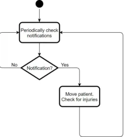
7 Activity Diagrams
As long as the system is active, the patients don’t have to do anything. As our system is designed for assisting caregivers, the caregivers activity will start with the patient falling asleep and end when the patient wakes up while constantly checking notifications in between as shown in Figure 11.
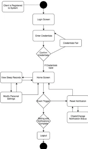
Figure 12: Caregiver Activity Diagram
This is complete activity diagram for the Caregiver. The Caregivers will log into the system to see the different notifications from the patients. If any of the patients trigger and warning and need to be moved, the Caregiver will have to reset the trigger by moving the patient. They can also access the patient’s sleep records so to avoid moving them into a position they have already been on and modify any of the sleep records as needed such as when they notice bruising on the patient.
8 Model
8.1 Hardware
As we are trying to minimize the amount of hardware on the patient. We are using a velcro attachable shirt that holds the gyroscope, set of sensors, the arduino, and a battery pack. This will all be mounted on the chest as shown in Figure 13.
Figure 13: Mounting Shirt
The pocket will hold the arduino and gyroscope and as you can see the sensors will be in locations known for developing pressure ulcers. The gyroscope and the arduino are relatively small and are shown in figures 14 and 15.
8.2 Software
Figure 16: Login
Caregivers will login according to our system on their hospital’s stations computer as well as on their own personal mobile/computer device with their own credentials if needed. They will then be able to see the different patients’ status as shown in Figure 17.
Figure 17: Patient Data on Homepage
From this homepage if they click the patient’s name they will be lead to another page that will expand on the patient’s specific information that includes a color coded image that indicates the areas that the patient has been lying on for longer periods of time shown by Figure 18. The red is areas that the patient has been on the longest, the yellow represents a medium amount of time and the blue represents the least amount of time. This helps the Caregiver to know areas of concern. Like in the Figure 18 the Caregiver would move this patient away from his right arm and left leg.
Figure 18: Color Coded Pressure on the Body
Our solution only has 7 sensors currently but we want to expand to the full body like the Figure 18. Note that Caregivers can also modify patient’s notes as well on this page. They can also navigate through different patients using the nav bar on the top of the web application.
10 Block Diagrams
10.1 Overarching Diagram
As you can see from figure 19, we have split the implementation to two different views. On the Patient’s side we are collecting the data using different sensors and performing different
operations on the Arduino. From the Arduino we transfer to the Server side which collects the data onto the database and presents the data on the web server.
10 Testing
To test our solution we mostly tested individual parts. As we only have seven sensors that would correspond to an individual person we were not able to test the data for multiple people so we split the software and hardware parts separately.
10.1 Software
For the software section we wanted to make sure that we were able to make our website easy to use and that the user interface was intuitive. To do this we had other people who were not knowledgeable about our project navigate the site and asked them to different tasks such as see how much time a certain patient had on a time as well as how they would be able to edit notes for another patient. We also wanted to make sure that we were correctly saving each patient’s data so we added different data into our database and checked to see if they correctly showed up.
Figure 20: Sensors and Arduino 10.2 Hardware
We tested the individual FSRs’ sensitivity and plotted their data on a graph on the arduino. We also set a timer on the arduino that would go off if any of the FSRs exceeded a certain threshold, and turn on an LED as an alert. The gyroscopic data is being integrated, but unfiltered noise in the signal makes the zero values change over time.
11 Societal Issues
1. Ethical
There were a lot of ethical concerns we had when starting this project. When we were still in early concept phase and just starting to consider pressure ulcers we were nervous about testing our project, and how it would be implemented. Regarding testing we found out we couldn’t test on humans as it would be a liability to the school if anything happened so we decided that our project would remain a prototype. As for the implementation it was very hard to create a solution that would be secure while being functional.
People’s sleeping information is considered private information so, we decided to make our implementation focus on the patients in a hospital setting as the hospitals already have the patient's medical information on hand and ensure privacy regarding its contents.
Since our solution revolves around the hospital’s infrastructure they have in place, our
implementation also takes advantage of the fact that the caregivers are already knowledgeable about pressure ulcers so there is less of a learning curve regarding our solution and there is a smaller chance of our solution failing.
2. Social
Everyone deserves to sleep comfortably and get proper rest without the risk of developing injuries. Pressure ulcers affects not only those who are injured/ill but those who are aging, have fragile skin, or even the people that have more weight. The scope of our project was very large, potentially. However as we are developing a prototype we decided to narrow the scope so that we may fully address the concerns with a smaller group rather than generally try to address the problems that the large majority faces. This narrowed scope of addressing only the people in hospital settings allowed us to consider many more possibilities with our implementation. However the solution we came up with is not one viable or recommended for the general public. On the other hand our solution not only helps the patients in the hospital setting but those that are working in the hospital/treating the patients by making their current pressure ulcer system more efficient.
3. Political
Our project is not political in nature however it may have potential political ramifications. By reducing the number of pressure ulcers and other injuries caused during a patient’s stay at a hospital, the national statistics and legal effects on hospitals and patients may change. Patients may be able to leave the hospital on time and would not require additional time due to receiving more injuries. This would help the patient save money because some health insurances such as medicaid do not cover the extra time when the injuries were sustained during their stay in the hospitals. This also is good for hospitals, as patients have sued hospitals on accounts of
negligence if the patient developed injuries that are easily preventable with sufficient care. If a hospital was able to reduce the number of injuries caused during all their patients’ stay, they will also have a higher reputation for caring for the patient which might convince others to come to their hospital over other hospitals. Also although the number of injuries sustained in the hospital are decreasing nationally, if we consider some hospitals internationally, pressure ulcers are not even addressed.
4. Economic
Originally we were going to try to use large pressure sensors on the bed to try to map the entire human body, but agreed it was unnecessary and expensive and the data might be hard to interpret as the patient's’ body might roll around making it hard to find out which part of the body was applying pressure on the sensors. After learning more information regarding pressure ulcers it became clear that there were common areas that develop pressure ulcers. By targeting a few of those areas the team could prevent most pressure ulcers from forming while also saving on the sensors. Also in the future we could do most of the functionality by changing the arduino onto a chip that has wifi/bluetooth connectivity. This would make the entire solution be a lot cheaper as they are the most expensive components although the price is already cheap considering the hospital’s alternatives.
5. Health and Safety
As our project is centered around caregiver-patient interaction so, we have to be very thoughtful in how we designed our project. Usually the patients that need our project are either very weak or need assistance in movements so we had to make sure that our project was non invasive/allowing movement and comfortable to use. Some of the team members have had experience working in nursing homes and hospital settings but the team decided as a whole that it would be better if we did not do any human testing for ethical/safety reasons. But we did consider many factors that would allow our project prototype to be easily worn by different patients. Such considerations include:
1. Mounting the sensors on a adjustable shirt that can be worn so as to not put the sensors directly on the patient’s body especially if the patient has sensitive skin.
2. Making the prototype small and limiting the amount of wires so that the body is still comfortable and is able to move
3. Making the prototype quiet so as to not wake the patient who is wearing our solution at night
4. Making sure there are no sharp edges, electric shocks, and etc. by taking many safety precautions
6. Manufacturability
Currently we have not designed the prototype in a way that is already able to be
manufactured. We would need to redesign several parts in order for our project to be more cost effective. We are using both an arduino to do our collection and transmission of data. This component could easily be replaced with a chip that has a storage and bluetooth/wifi capabilities which would bring down the cost a lot. This could allow for more sensors. Currently we have only designed our prototype to monitor and display the data from the upper torso of a human body but we believe we can extend this to the whole body. If increasing the sensors make the cost too expensive we might consider switching from pressure sensors to a cheaper alternative such as a button (doesn’t have pressure sensitivity but will turn on when pressed). As we currently haven’t spoken to any manufacturing companies or any hospitals regarding pricing strategy, distributions channels, or marketing we also don’t know how valuable our project is.
7. Sustainability
Our project is very handy because it is a simple and effective solution to a problem that will always exist. As injuries occur more people will be moved to the hospital, and unless the hospital is properly staffed at all times our project will be relevant. Our project could be expanded later on to include air bladders as we initially planned to do so. This would avoid having our system to rely on nurses to manually move the patient but, our right now our solution is still cheaper and remains just as effective. There are also a couple more adjustments that could be made regarding how the sensors would be placed on the patient. For example the sensors on the shirt could bunch up and still require the nurse to readjust the placement on the patient. However we do not know if there is a better implementation method of placing the sensor to get the same data from the patient so more research would be needed.
8. Environmental Impact
In our prototype we have, 7 pressure sensors, one gyroscope, an arduino, a few wires, and a light. Everything is pretty small and low impact other than the arduino board. However as it is already a widespread product its company have done different things to bring down the environmental impact.
“For every two Arduino boards manufactured by Smart Projects, one square meter of rainforest will be restored or protected from deforestation. This donation has been in effect from the beginning of production of the Arduino Mega in an effort to make the production of Arduino boards closer to carbon neutral.”3
Another consideration we still have yet to solve is the use of rechargeable batteries in our solution or to rely on power outlets by the hospitals to see which is more cost effective while remaining environmentally friendly. Generally though our product is small and easy to manufacture minimizing its impact on the environment.
9. Usability
Our project has components that utilizes modern technological communications. As our system relays information on a web server, we are able to visually notify caregivers about situations regarding patients. The notification is visible through our web application. The web application has been created so nurses can easily navigate the data and understand the patients status. To make sure that our web application was more accessible for all nursers, we favored a simple UI design. Although the development of ulcers is a slow process nurses still have to continually check the web application and make sure the patient is moving for our system to be useful. So it can be said that our solution only works if there is a computer running our system continuously. This is not a problem in most hospitals as most nurses have a department station in which they continuously check in with, as well as have a smartphone, which can also load our web
application. In any case most hospitals would be able to deploy our solution and most caregivers should be able to use our solution well if given a bit of instruction.
10. Lifelong Learning
For the past four years both Rey and Ojus have taken many different courses in Santa Clara University. Pressure Ulcers however, was not part of their curriculum. This mean that they had to address a problem that was out of the scope of their majors and had to rely on themselves to figure out what needed to be done. With advisors from both the ELEN and COEN
departments of their school helping them develop a framework for a project, they began
researching methods they could implement to help find a solution for pressure ulcers. They also met up with a few doctors and consulted with a sleep lab to get more details on the subject. Through their passion they progressed in the project and was able to come up with a new ideas. When presenting their solution to others in senior design and tabling afterword, many people expressed their excitement over the design and wished for it to be a viable product. This experience definitely revalidated the team’s efforts and helped them understand the difference their product could make.
11. Compassion
As Engineers and students of Santa Clara we wanted our project to encompass not only real life problems but the SCU Mission Statement and the Mission Statement for the School of Engineering. As both team members have grown up in families that were heavily involved in the healthcare industry, our project ideas centered on alleviating or preventing more problems for both patients and health care workers.
Originally Rey was inspired through a senior design project from the previous year. They had mapped where pressure was being applied on the foot when doing squats and similar
exercises. He wanted to apply this in a hospital setting and map patient’s movements to prevent falls. However after more research we found out that patients falls had been nationally addressed. So, Ojus suggested they try switching to the more underrated but commonly occurring problem regarding preventing pressure ulcers instead. Unlike most big name diseases, pressure ulcers happen gradually and are easily preventable. There are a few solutions to try to prevent pressure ulcers yet pressure ulcers are still prevalent in many hospitals.
The more the team talked with sleep labs and other specialists the more people expressed enthusiasm for our idea. However the team ran into many problems while researching statistics of pressure ulcers. Many of the articles were written in the late 90’s or early 2000’s and had conflicting information regarding the percentage of patients who developed pressure ulcers in a hospital setting, the number of deaths related to pressure ulcers, and how much it cost the patients or hospital to treat the injury. According to AHRQ (Agency for Health Care Research and Quality aka the US Department on Health and Human Services)
“Pressure Ulcers affect: 2.5 million patients per year. Pressure ulcers cost $9.1-$11.6 billion per year in the US. Cost of individual patient care ranges from $20,900 to 151,700 per pressure ulcer. Medicare estimated in 2007 that each pressure ulcer added $43,180 in costs to a hospital stay. More than 17,000 lawsuits are related to pressure ulcers annually. It is the second most common claim after wrongful death and greater than falls or emotional distress.
Pressure ulcers may be associated with severe pain. About 60,000 patients die as a direct result of a pressure ulcer each year.”
Even with so many reasons to prevent pressure ulcers most hospitals find the issue to be very complex often associating the problem with the organization of the healthcare system and would say they would need “multiple, simultaneous modifications to workflow, communication, and decision making”. Pressure Ulcers are an even bigger problem outside the US.
As we continued our research on pressure ulcer the more we felt compelled to tackle the problem. Although neither of the team members were bio-engineers we believed we could create a system that would not only identify when pressure ulcers were more likely occur but also help with the communication issues that might arise in a hospital setting and multiple patients to look after. We considered many issues and developed our solution to address them with the hope that our product will help inspire others to make changes regarding pressure ulcers.
12 Conclusions
12.1 What we learned
During the course of this project, we learned about pressure ulcers: how they develop, the problems they cause, and how to prevent them. We learned that there is an untapped market in the middle ground between absolute prevention and temporary, one-time use risk-suppressors.
While trying to create a solution, we learned that there are dozens of sensors and approaches that we could have taken, and that we were most limited by our budget and deadlines. We learned to include a budget for spare parts, and for unexpected substitutions in hardware.
Although not something newly learned, our ability to work from documentation and research was reinforced, such as establishing communication between the sensors and the processing unit; neither of us had any prior experience with I2C, but it was essential to the project, so we taught ourselves what we needed to know.
Maybe most importantly, we learned to reevaluate what we had accomplished because we ultimately could not meet all our goals, but we had accomplished much more than nothing. Our original intention was to have a fully-functioning prototype by the end. Instead, we had two separate proof of concept models and demos.
12.2 Setbacks
We went through many obstacles but the biggest was time management. Both team members had a hard time with meeting each other and progressing individually as they were both very busy and had a hard time communicating themselves. We think these problems would be better ameliorated with another team member who was also familiar with either electrical engineering
or computer engineering. This was due to the team constantly changing the scope and
implementation of the system. By changing the concept multiple times the team members also became confused of what was expected from them and how to go about the solution.
12.3 Future Developments
We still have to connect both parts of the solution as they are not working together. Then we can also add a better image map to the individual patient’s page as well as a timer that automatically resets to the website. We also have to interpret the gyroscope information so that we can
understand the 3d plotted information better. If we are able to get all of these working smoothly we can also look to implementing a air bladder system as we originally imagined to be self sustaining and not be reliant on Caregivers in a hospital setting.
13 References
1) Arjo. “Best in Class Non-Powered Mattress for All Acuities.” Specifications - ArjoHuntleigh,
2018,
www.arjohuntleigh.us/products/therapeutic-support-systems/home-care/non-powered-pressure-re distribution/evolve/.
2)Alibaba Group. “1pc FSR402 0.5’ Film Force Sensitive Resistor Pressure Force Sensor For
Long Tail 60mm*19mm 0g~10kg Force Sensing-in Pressure Sensors .” Aliexpress.com,
www.aliexpress.com/item/1pc-FSR402-0-5-Film-Force-Sensitive-Resistor-Pressure-Force-Senso r-For-Long-Tail-60mm-19mm/32836398065.html.
3) Tigoe. “Arduino Manufacturing and Carbon Neutrality.” Arduino Blog RSS, 10 Mar. 2011,
blog.arduino.cc/2009/10/13/arduino-manufacturing-and-carbon-neutrality/.
4) “Arduino Mega 2560 Rev3.” Arduino Uno Rev3,
store.arduino.cc/usa/arduino-mega-2560-rev3.
5) Brem, Harold, et al. High Cost of Stage IV Pressure Ulcers, U.S. National Library of Medicine, Oct. 2010, www.ncbi.nlm.nih.gov/pmc/articles/PMC2950802/.
6) Edlich, Richard, et al. Pressure Ulcer Prevention. Journal of Long-Term Effects of Medical Implants, Begel House Inc., 2004,
www.dl.begellhouse.com/journals/1bef42082d7a0fdf,2415cf3075781f88,3f4ec30966d913da.htm l.
7) “Infrared Patient Bed Alarm.” Medline Industries, Inc., 2017,
www.medline.com/product/Infrared-Patient-Bed-Alarm/Alarms/Z05-PF11941.
8) “National Center for Health Statistics.” Centers for Disease Control and Prevention, 19 Jan.
2010, www.cdc.gov/nchs/products/databriefs/db14.htm.
9) Molnlycke HealthCare. “Mepilex Sacrum Buttocks Sores Prevention Pad/ Bandage 7.2 X
7.2.” Careline Medical,
www.carelinemedical.com/products/Mepilex-Border-Sacrum-282000-18-X-18-cm/?gclid=EAIaI
10) “Pressure Ulcer Risk Spots - National Library of Medicine - PubMed Health.” Pressure Ulcer Risk Spots, U.S. National Library of Medicine,
www.ncbi.nlm.nih.gov/pubmedhealth/PMHT0025822/.
11) “Preventing Pressure Ulcers in Hospitals.” AHRQ--Agency for Healthcare Research and
Quality: Advancing Excellence in Health Care, U.S. HHS: Agency for Healthcare Research and Quality, 2 Oct. 2014,
www.ahrq.gov/professionals/systems/hospital/pressureulcertoolkit/putool1.html.
12) “Raspberry Pi 3 Model B.” Raspberry Pi,
www.raspberrypi.org/products/raspberry-pi-3-model-b/.
13) Steele, John. “SparkFun IMU Breakout - MPU-9250.” SEN-13266 - SparkFun Electronics,
14 Appendices
Appendix A: Web Technologies Used
HTML: Hypertext Markup Language is used primarily for displaying any content we are writing, in a web page format.
CSS: Cascade Style sheet is for adding stylistic components on our web page.
JavaScript: Essential for when we want to create interactive components to our web page to make it more user friendly.
PHP: PHP Hypertext Preprocessor will be used for any input collection from the user and as an interface for the database.
MySQL: Language for querying and modifying the database.
Appendix B: Proof of Concept Graphs - FSR
In this appendix, a single test case is represented by a vertical pair of graphs. The sensor readings are in the top graph, the corresponding alert status is in the bottom graph
Appendix C: Proof of Concept Graphs - Gyroscopic Module
For this appendix, the x-axis of the patient is the anterior-posterior axis, the y-axis is the transverse axis, and the z-axis is the longitudinal axis. Below is a reference picture.
(Source: Lynbrook Vision Centre)
Appendix D: Proof of Concept - FSR Code // Defines # define NumSensors 7 # define NumBits 16 # define ChangePin 16 # define SignalPin 52 # define InterruptPin 20
# define SensorPeriod 000 // milliseconds # define DataHold 200 // milliseconds # define OnAlert 75 // rounds of checking # define AlertThreshold 700 // out of 1024 // Includes /* None */ // Globals int sensor[NumSensors]; int sensorBinary[NumSensors][NumBits]; int OnTime[NumSensors];
int changed = LOW;
volatile bool sendData = false; int alert = 0;
// ISR is intterupt code void isr()
{
sendData = true; }
// Setup Runs Once void setup()
{
Serial.begin(9600);
// Setup binary output pins for(int i = 0; i < NumBits; i++) {
pinMode(i, OUTPUT); }
// Setup binary data change pin pinMode(ChangePin,OUTPUT); // Setup signal pin
pinMode(SignalPin, OUTPUT); // Setup digital interrupt pin
attachInterrupt(digitalPinToInterrupt(InterruptPin), isr, RISING); }
// Loop Runs Indefinitely void loop()
{
// Collect data from sensors noInterrupts();
//Serial.println("Sensor 1:\tSensor 2:\tSensor 3:\tSensor 4:\tSensor 5:\tSensor 6:\tSensor 7:");
for(int i = 0; i < NumSensors; i++) {
sensor[i] = analogRead(i); // TIMING FOR LIGHT
if(sensor[i] < AlertThreshold) { OnTime[i] += 1; if(OnTime[i] >= OnAlert) { digitalWrite(SignalPin,HIGH); alert = 1; } } else { OnTime[i] = 0; } Serial.print(sensor[i]); Serial.print("\t"); for(int j = 0; j < NumBits; j++) {
sensorBinary[i][j] = (sensor[i] << (NumBits - 1 - j)) >> (NumBits - 1); }
}
// CHECK LIGHT
if(OnTime[0] < OnAlert && OnTime[1] < OnAlert && OnTime[2] < OnAlert && OnTime[3] < OnAlert && OnTime[4] < OnAlert && OnTime[5] < OnAlert && OnTime[6] < OnAlert) { digitalWrite(SignalPin,LOW); alert = 0; } Serial.print("1024\t0"); Serial.print("\t"); Serial.print(alert*500); //Serial.print("\n"); Serial.print("\n"); interrupts();
// Send data if requested noInterrupts();
{ digitalWrite(j,sensorBinary[i][j]); } changed = !changed; digitalWrite(ChangePin,changed); delay(DataHold); } } interrupts(); delay(SensorPeriod); }
Appendix E: Proof of Concept - Gyroscopic Module Code #include <Wire.h> #include <TimerOne.h> #define MPU9250_ADDRESS 0x68 #define MAG_ADDRESS 0x0C #define GYRO_FULL_SCALE_250_DPS 0x00 #define GYRO_FULL_SCALE_500_DPS 0x08 #define GYRO_FULL_SCALE_1000_DPS 0x10 #define GYRO_FULL_SCALE_2000_DPS 0x18 #define ACC_FULL_SCALE_2_G 0x00 #define ACC_FULL_SCALE_4_G 0x08 #define ACC_FULL_SCALE_8_G 0x10 #define ACC_FULL_SCALE_16_G 0x18 #define CALIBRATION_READINGS 500 #define AVG_READINGS 3 #define NOISE_LOW_BOUND -20 #define NOISE_HIGH_BOUND 20 // Zero Offset int16_t gx_zero_offset = 0; int16_t gy_zero_offset = 0; int16_t gz_zero_offset = 0; // Continuous Orientation long int orient_x = 0; long int orient_y = 0; long int orient_z = 0;
// Initial time long int ti;
volatile bool intFlag=false; // Initializations void setup() { // Arduino initializations Wire.begin(); Serial.begin(115200);
// Set accelerometers low pass filter at 5Hz I2CwriteByte(MPU9250_ADDRESS,29,0x06);
// Set gyroscope low pass filter at 5Hz I2CwriteByte(MPU9250_ADDRESS,26,0x06);
pinMode(13, OUTPUT);
Timer1.initialize(10000); // initialize timer1, and set a 1/2 second period Timer1.attachInterrupt(callback); // attaches callback() as a timer overflow interrupt
// Store initial time ti=millis();
// CALIBRATE THE GYROSCOPE OUTPUT int64_t gx_zero_offset_counter = 0; int64_t gy_zero_offset_counter = 0; int64_t gz_zero_offset_counter = 0; uint8_t Buf[14];
for(int i = 0; i < CALIBRATION_READINGS; i++) {
I2Cread(MPU9250_ADDRESS,0x43,6,Buf);
gx_zero_offset_counter += -(Buf[0]<<8 | Buf[1]); gy_zero_offset_counter += -(Buf[2]<<8 | Buf[3]); gz_zero_offset_counter += Buf[4]<<8 | Buf[5]; Serial.print((int)gx_zero_offset_counter); Serial.print("\t"); Serial.print((int)gy_zero_offset_counter); Serial.print("\t"); //Serial.print((int)gz_zero_offset_counter); //Serial.print("\t"); Serial.println(""); }
gx_zero_offset = gx_zero_offset_counter / CALIBRATION_READINGS; gy_zero_offset = gy_zero_offset_counter / CALIBRATION_READINGS; gz_zero_offset = gz_zero_offset_counter / CALIBRATION_READINGS; delay(2000); } // Counter /*long int cpt=0;*/ void callback() { intFlag=true; digitalWrite(13, digitalRead(13) ^ 1); }
// Timer for Integral
long int previous = millis(); long int current = millis();
// Main loop, read and display data void loop()
while (!intFlag); intFlag=false; // Read gyroscope uint8_t Buf[14]; int avg_gx = 0; int avg_gy = 0; int avg_gz = 0; int16_t test_gx; int16_t test_gy; int16_t test_gz;
for(int i = 0; i < AVG_READINGS; i++) {
I2Cread(MPU9250_ADDRESS,0x43,6,Buf);
test_gx = -(Buf[0]<<8 | Buf[1]) - gx_zero_offset; test_gy = -(Buf[2]<<8 | Buf[3]) - gy_zero_offset; test_gz = (Buf[4]<<8 | Buf[5]) - gz_zero_offset; avg_gx += test_gx; avg_gy += test_gy; avg_gz += test_gz; } avg_gx /= AVG_READINGS; avg_gy /= AVG_READINGS; avg_gz /= AVG_READINGS;
if(NOISE_LOW_BOUND < avg_gx && avg_gx < NOISE_HIGH_BOUND) avg_gx = 0;
if(NOISE_LOW_BOUND < avg_gy && avg_gy < NOISE_HIGH_BOUND) avg_gy = 0;
if(NOISE_LOW_BOUND < avg_gz && avg_gz < NOISE_HIGH_BOUND) avg_gz = 0; current = millis(); orient_x += avg_gx; orient_y += avg_gy; orient_z += avg_gz; Serial.print("Z: "); Serial.print(orient_x); Serial.print ("\t"); Serial.print("Y: "); Serial.print(orient_y); Serial.print ("\t"); Serial.print ("400000"); Serial.print ("\t"); Serial.print ("-400000");