Evaluation of a Virtual Firewall in
a Cloud Environment
Clement Berthelot
09014406
Submitted in partial fulfilment of
the requirements of Edinburgh Napier University
for the Degree of
MSc Advanced Networking
School of Computing
December 2011
Supervisor: Prof William Buchanan
Second Marker: Dr Gordon Russell
Authorship Declaration
I, Clement Berthlelot, confirm that this disseration and the work presented in it are my own achievement.
Where I have consulted the published work of others this is always clearly attributed;
Where I have quoted from the work of others the source is always given. With the exception of such quotations this disseration is entirely my own work; I have acknowledged all main sources of help;
If my research follows on from previous work or is part of a larger collaborative research project I have made clear exactly what was done by others and what I have contributed myself;
I have read and understand the penalties associated with Academic Misconduct.
I also confirm that I have obtained informed consent from all people I have involved in the work of this dissertation following the School‟s ethical guidelines
Signed: Date:
Matriculation no: 09014406
PLEASE NOTE that in signing this page you are aware of the consequences of doing this fraudulently as explained at
Data Protection Declaration
Under the 1998 Data Protection Act, The University cannot disclose your grade to an unauthorised person. However, other students benefit from studying theses that have their grades attached.
The University may make this Thesis with indicative grade, available to others.
The University may make this Thesis available to others, but the grade may not be disclosed.
Contents
Acknowledgements ... 8
Abstract ... 9
1 Introduction ... 10
1.1 Context ... 10
1.2 Aim and Objectives ... 10
1.3 Thesis Structure ... 11
2 Literature Review ... 12
2.1 Introduction ... 12
2.2 Virtualization ... 12
2.2.1 Architecture of x86 processors ... 12
2.2.2 Types of Virtualization ... 13
2.2.3 Virtual Machine Monitor ... 14
2.3 Cloud Computing ... 15
2.3.1 Definition of Cloud Computing ... 15
2.3.2 Architecture of Cloud Computing ... 16
2.3.3 Deployment of Cloud Computing ... 17
2.3.4 Economics of Cloud Computing ... 17
2.4 Network Security ... 18
2.4.1 Firewalls ... 18
2.4.2 Network firewalls in cloud environment ... 20
2.4.3 Virtual Firewalls ... 20
2.5 Network Security Threat ... 21
2.5.1 Viruses, Worms and Trojans ... 21
2.5.2 Network Scanning ... 22
2.5.3 User Privilege Gain ... 22
2.5.4 Denial of Service Attacks ... 22
2.6 Methodologies in Evaluating Firewalls ... 23
2.6.1 Evaluation Metrics ... 23
2.6.2 Black-‐Box and White-‐Box Testing ... 24
2.6.3 Real-‐time and Offline Evaluation ... 25
2.6.4 DARPA Evaluation ... 26 2.6.5 Automated Evaluation ... 26 2.6.6 LARIAT Evaluation ... 27 2.6.7 Trident Evaluation ... 27 2.7 Conclusion ... 28 3 Design ... 30 3.1 Introduction ... 30 3.2 Cloud infrastructure ... 30 3.3 Virtual Firewall ... 32 3.4 Evaluation Scenarios ... 33 3.4.1 IP Throughput ... 33 3.4.2 Latency ... 34 3.4.3 Goodput ... 36 3.4.4 HTTP Transfer Rate ... 37 3.4.5 DoS Handling ... 38
3.4.6 Hardware and Energy Consumption ... 39
3.5 Evaluation Tools ... 40
3.5.1 Iperf ... 40
3.5.3 Wireshark ... 41 3.5.4 HrPing ... 41 3.5.5 HPing ... 41 3.6 Conclusion ... 42 4 Implementation ... 43 4.1 Introduction ... 43 4.2 Cloud Implementation ... 43
4.2.1 Node Implementation with Xen ... 43
4.2.2 Frontend Implementation with OpenNebula ... 45
4.2.3 Virtual Firewall Implementation ... 48
4.3 Evaluation ... 49 4.3.1 IP Throughput ... 49 4.3.2 Latency ... 50 4.3.3 Goodput ... 50 4.3.4 HTTP Transfer Rate ... 51 4.3.5 DoS Handling ... 52
4.3.6 Hardware and Energy Consumption ... 53
4.4 Conclusion ... 54 5 Evaluation ... 55 5.1 Introduction ... 55 5.2 Results ... 55 5.2.1 IP Throughput ... 55 5.2.2 IP Latency ... 56 5.2.3 Goodput ... 59 5.2.4 HTTP Transfer Rate ... 60 5.2.5 DoS Handling ... 61 5.2.6 Hardware Consumption ... 62 5.3 Critical Analysis ... 64 5.4 Conclusion ... 64 6 Conclusion ... 66 6.1 Introduction ... 66
6.2 Meeting the Objectives ... 66
6.2.1 Objective 1 -‐ Review and investigate the literature in the field of cloud computing, virtual firewall and evaluation methodologies ... 66
6.2.2 Objective 2 -‐ Design of proper evaluation scenarios to evaluate a virtual firewall in a cloud environment based on the findings of the literature review ... 67
6.2.3 Objective 3 -‐ Implement a cloud infrastructure with a virtual firewall, along with evaluation tools to realize the design specifications ... 67
6.2.4 Objective 4 -‐ Evaluate the performances of the virtual firewall in the implemented cloud infrastructure ... 68
6.3 Reflection ... 68
6.4 Future Work ... 69
7 Bibliography ... 70
Appendix 1 – Gantt Chart ... 74
Appendix 2 – Evaluation Data ... 75
Appendix 3 – OpenNebula Configuration files ... 79
Appendix 4 – Firewall Scripts ... 80
List of Figures
Figure 2.2.1 – Architecture of x86 processor ... 12
Figure 2.2.2 – Full virtualization technique (VMWare, 2007) ... 13
Figure 2.2.3 – Paravirtualization technique (VMWare, 2007) ... 14
Figure 2.2.4 – Hardware-assisted virtualization technique (VMWare, 2007) ... 14
Figure 2.3.1 – Architecture of Cloud Computing with an email application (Gabrielsson et al, 2010) ... 16
Figure 2.3.2 – Bing search volume over 24h period (Microsoft, 2010) ... 17
Figure 2.4.1 – Typical network infrastructure ... 18
Figure 2.4.2 – Packet filtering process (Macfarlane, 2010) ... 19
Figure 2.4.3 – Physical firewall blind to the virtual traffic ... 20
Figure 2.6.1 – Trident Framework (Sommers et al, 2004) ... 28
Figure 3.2.1 – Cloud infrastructure to be implemented with OpenNebula and Xen ... 31
Figure 3.3.1 – Xen Network-bridging (XenNetworking, 2011) ... 32
Figure 3.3.2 – Iptables configuration example ... 32
Figure 3.4.1 – IP Throughput evaluation with Iperf ... 34
Figure 3.4.2 – Latency evaluation with Iperf and HrPing ... 35
Figure 3.4.3 – Goodput evaluation with Iperf ... 37
Figure 3.4.4 – HTTP Transfer Rate evaluation with Httping and Iperf ... 38
Figure 3.4.5 – DoS Handling evaluation with Hping and Httping ... 39
Figure 4.2.1 – Virtual Manager/Virt Viewer during the a VM installation ... 44
Figure 4.2.2 – FrontEnd Terminal: Onehost list output ... 47
Figure 4.2.3 – Overall Network Infrastructure ... 48
Figure 4.2.4 – Firewall script used to flush and then reconfigure the filtering table ... 49
Figure 4.3.1 – Firewall script used in the 50% legal traffic scenario ... 51
Figure 4.3.2 – Firewall script used in the DoS Handling scenario ... 52
Figure 4.3.3 – CPU Usage report generated by Sar ... 53
Figure 5.2.1 – IP Throughput of the virtual firewall ... 55
Figure 5.2.2 – IP Throughput in parallel with the number of Filtering Rules on the virtual firewall ... 56
Figure 5.2.3 – Round-trip Latency to reach the virtual firewall (0 filtering rules) ... 57
Figure 5.2.4 – Round-trip Latency to reach the virtual firewall (1000 filtering rules) .. 57
Figure 5.2.5 – Round-trip Latency to reach the virtual firewall (10 000 filtering rules) ... 58
Figure 5.2.6 – Round-trip Latency to reach the virtual firewall (50 000 filtering rules) ... 58
Figure 5.2.7 – Goodput of the virtual firewall ... 60
Figure 5.2.9 – Denial-of-Service Handling of the virtual firewall ... 61 Figure 5.2.10 – CPU and Memory Usage of the Node machine (throughput level) ... 62 Figure 5.2.11 – CPU and Memory Usage of the Node machine (SYN rate) ... 63
List of Tables
Table 2.6.1 – Additional Firewall performance evaluation metrics (Snyder, 2010; Hickman et al, 2003) ... 24 Table 5.2.1 – Average Latency introduced by the virtual firewall ... 59
Acknowledgements
I would like to thank Professor William Buchanan for his guidance and supervision in this project, and Doctor Gordon Russell for being my second marker. I would also like to thank Richard Macfarlane for his ideas and advices that led me to choose this subject.
Finally, thanks are directed to the MAP/GAMSAU Company, and especially to Pascal Bénistant, for providing me with the required resources to carry out the evaluation part of this project.
Abstract
Many researches show that virtualization and cloud computing are technologies that will be essential in the future. They are already widely used because of the many advantages they introduce. They permit to reduce hardware cost, reduce the energy consumption, and ease the management of an ever-growing number of computers and servers. However, this abrupt switch from physical infrastructures to virtualized ones introduces a new networking aspect, the virtual traffic, and poses the question of how to secure this new type of traffic. In fact, virtual traffic between two virtual machines may never leave the physical host hardware; making traditional physical firewalls useless to monitor and secure this traffic. The best solution to this problem is the use of virtual firewalls.
The aim of this project is to evaluate the performances of a virtual firewall in a cloud environment. This thesis reviews the literature in the field of cloud computing and virtual firewall and concludes that three key requirements must be met in order to realize an effective evaluation: the choice of a cloud infrastructure, the choice of meaningful evaluation metrics and the use of proper evaluation methodologies.
Using open source solutions, a private cloud is designed and implemented with OpenNebula as a cloud toolkit and with Xen as a hypervisor. The Linux iptables virtual firewall is chosen to secure the cloud, and implemented in a strategic point of the virtual network infrastructure to work as a bridge-mode firewall. Based on the literature review findings, the following evaluation metrics are chosen to evaluate the virtual firewall: IP throughput, latency, goodput, HTTP transfer rate, Denial-of-Service handling and hardware consumption. Evaluation scenarios to measure these metrics are designed with the cloud infrastructure in mind.
By implementing these evaluations scenarios in the cloud infrastructure using different tools, the virtual firewall is evaluated. Overall, the results show that the performances of the virtual firewall decrease in different situations: traffic sent with small frame sizes, large amount of rules in the filtering table, high throughput levels. It also highlighted the difficulty for a firewall to protect a network against SYN Denial-of-Sevice attacks.
The conclusion made in this thesis highlights the fact that the evaluation results were the ones expected, confirming that the choice and implementation of the evaluation methodologies are correct. However, several limitations are also found. The main limitation involves the latency evaluation methodology, which had the goal of measuring the latency produced by the virtual firewall. It was in fact impossible to find a technique to measure this metric, and the round-trip latency of a connection to the virtual firewall was instead evaluated. Finally, the conclusion shows that more work should be done, especially in regards of evaluating additional virtual or physical firewalls using the same metrics and infrastructure, to provide means of comparison with the performances of the Linux iptables virtual firewall.
1 Introduction
1.1 Context
In computing, virtualization refers to the creation of virtual versions of computers or operating systems where the physical characteristics of a computing platform are hidden from users. The software that controls the virtualization is called hypervisor. Virtualization benefits are multiple (Leja et al, 2008): it permits not only to reduce costs (electrical, space, hardware) by lowering the number of physical machines, but it also eases the management of an ever-growing number of computers and servers. It is not surprising that the analysis firm Gartner predicts that 50 percent of workload will run inside virtual machines by 2012.
However, virtualization is both an opportunity and a threat. According to Ben-Efraim (2011), collapsing multiple servers into a single one with several virtual machines inside results in eliminating all firewall and other protections in existence prior to the virtualization. Traditional “physical security measures literally become blind to traffic between virtual machines” since the virtual network traffic may never leave the physical host hardware. Gartner (2010) predicts that through 2012, 60 percent of virtualized servers will be less secure than the physical servers they replace.
The solution to this issue is the use of virtual firewalls (Haletky, 2008). A virtual firewall is a firewall service running in a virtualized environment and providing the usual packet filtering and monitoring services that a physical firewall would provides. Four types of virtual firewalls can be distinguished: a traditional software firewall installed on a guest virtual machine; a purpose-built virtual security appliance designed with virtual network security in mind; a virtual switch with additional security capabilities; or a managed kernel process running on the host hypervisor that sits atop all virtual machines activity. These technologies are meant to answer the new network security concerns raised by virtualized environment (Moore, 2008).
1.2 Aim and Objectives
The overall aim of this project is to evaluate the performances of a virtual firewall in cloud environment. In order to meet this aim, the following four objectives are defined:
1. Review and investigate the literature in the field of cloud computing, virtual firewall and evaluation methodologies.
2. Design of proper evaluation scenarios to evaluate a virtual firewall in a cloud environment based on the findings of the literature review.
3. Implement a cloud infrastructure with a virtual firewall, along with evaluation tools to realize the design specifications.
4. Evaluate the performances of the virtual firewall in the implemented cloud infrastructure.
1.3 Thesis Structure
The Thesis is divided in six main chapters. They are described as follows: • Chapter 1 – Introduction: Introduces the project overview to the subject of cloud computing, virtual firewalls and evaluation methodologies. They key aim and objectives of the project are described as well as the thesis structure. • Chapter 2 – Literature Review: Provides research and review of literature in the area of cloud computing, virtual security and evaluation methodology. A review of virtualization is provided, along with research on cloud computing showing its strengths and weaknesses, the different types in use and its deployment means. Then firewalls are reviewed pointing out their incompatibility with virtual traffic, leading to introduce the few solutions to this problem. Typical network security threats that firewalls should prevent are also explored. Finally, methodologies in evaluating firewall are analysed before reaching a conclusion to this chapter, identifying the key requirements for the design stage of this project.
• Chapter 3 – Design: Based on the key requirement found in the literature review, this chapter introduces a design of a cloud infrastructure secured with a virtual firewall, along with the design of evaluation scenarios permitting to evaluate this virtual firewall with different tools.
• Chapter 4 – Implementation: Describes the implementation of the cloud infrastructure and evaluation scenarios previously introduced. The installation and configuration steps taken are fully detailed with the use of screenshots and snippet of commands used.
• Chapter 5 – Evaluation: Using the evaluation scenarios implemented in the previous chapter, this chapter presents the results found when evaluating the virtual firewall. A critical analysis of the results is also made.
• Chapter 6 – Conclusion: Provides a final conclusion by identifying how well the aims and objectives of this thesis were met. A reflection on the difficulties encountered during this project is made. Finally, recommendations for future work in this area of research are made.
2 Literature Review
2.1 Introduction
This chapter investigates and reviews the literature in the field of cloud computing, virtual firewall and evaluation methodologies. It first provides a background to virtualization and outlines the different types existing in this technology (Section 2.2). It then focuses on a review of cloud computing in general along with its economical impact (Section 2.3). To understand the basic concept of firewalls and their role in a virtualized environment, a study of this topic is carried out (Section 2.4). The most common network security threats like DoS attacks or network scanning are then reviewed (Section 2.5) to get an idea of what a firewall should be able to block.
The main part of the review, methodologies in evaluating firewalls (Section 2.6), is then introduced presenting well-known evaluation methodologies like DARPA or Trident evaluations along with evaluation metrics applied to firewalls. Finally, a conclusion (Section 2.7) based on the literature reviewed identifies the key requirements for carrying out an effective evaluation of virtual firewalls.
2.2 Virtualization
2.2.1 Architecture of x86 processors
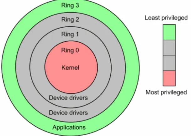
To understand virtualization, it is important to understand the design of the x86 processors family. They are designed with 4 levels of privileges called rings with ring 0 being the most privileged and ring 3 the least privileged (Intel Corporation, 1986). Therefore, ring 0 contains the most critical software which is usually the kernel of the operating system (or OS). This is shown in Figure 2.2.1.
Figure 2.2.1 - Architecture of x86 processor
Originally, x86 processors did not support virtualization. In 2005 and 2006, Intel and AMD started to modify the architecture of their x86 processors to
add proper support to virtualization: the Hypervisor in charge of the virtualization runs on the ring 0 while the kernel of the OS runs on the ring 1. 2.2.2 Types of Virtualization
IBM invented the concept of virtual machine (Creasy, 1981; Goldberg, 1974). The term virtualization first appeared in the 1960s with the IBM M44/44X experimental computer system, which was based on the M44 system but simulated multiple virtual 44X machines using both hardware and software. It was a pure research system used to explore the virtual machine concept and performance measurement. IBM defined a virtual machine as a fully protected and isolated copy of the physical machine’s hardware (Sugerman et al, 2001). Thus, virtualization refers to the emulation of computer components such as storage, memory, network and so on, giving a virtual machine user the illusion of having a dedicated physical machine. To virtualize the hardware of a machine, the use of a Hypervisor or Virtual Machine Monitor (VMM) is required.
The main goals of virtualization are to improve the hardware utilisation and the workload balance to a maximum, decrease the hardware cost by reducing the number of physical machines, decrease the energy consumption, and ease system management by centralizing administrative tasks. There are three main techniques to virtualize a guest OS: full virtualization, paravirtualization and hardware-assisted virtualization.
Full virtualization permits to virtualize any x86 OS without the need of modifying them. To allow the guest OS to run on ring 1, a binary translation technique is used (Figure 2.2.2). This technique provides full virtualization and the guest OS is not aware it is being virtualized, thus requiring no modification. Also, guest OS can access all the services of the physical system as a virtual BIOS, virtual devices and virtualized memory management (VMware, 2007).
Figure 2.2.2 - Full virtualization technique (VMWare, 2007)
Full virtualization offers the best isolation and security for virtual machines while simplifying portability and migration as a guest OS can both run virtualized or on native hardware. However, because full virtualization uses a full trap-and-emulate scheme to virtualize a machine, it is the technique that
presents the most overhead (Kloster et al, 2007). Microsoft Virtual Server or Parallels are examples of full virtualization.
Paravirtualization allows communication between the guest OS and the hypervisor to improve performance and efficiency. However, it involves modifying the OS kernel to replace non-virtualizable instructions with hypercalls that can communicate directly with the VMM in the virtualization layer (Figure 2.2.3). If this technique presents lower overhead than the other virtualization methods, it also brings compatibility and portability issues as unmodified OS are not supported (VMware, 2007).
Figure 2.2.3: Paravirtualization technique (VMWare, 2007)
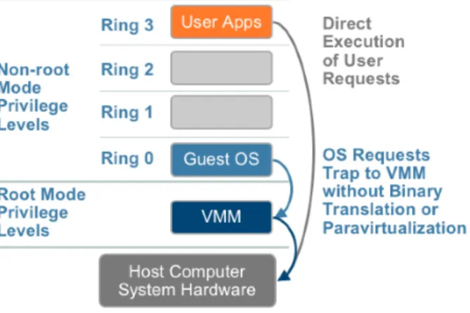
Hardware-assisted virtualization is only possible since 2005 with the new Intel and AMD x86 processors fully supporting virtualization (Intel VT and AMD-V). Those processors allow the VMM to run in a new privileged mode below ring 0 (Figure 2.2.4) and OS requests are automatically trapped without need of binary translation or paravirtualization (VMWare, 2007).
Figure 2.2.4 - Hardware-assisted virtualization technique (VMware, 2007) 2.2.3 Virtual Machine Monitor
A Virtual Machine Monitor (VMM) is a thin software layer that is used to map virtual resources to physical resources. Therefore, it allows multiple guests
OSs to run on a single host computer. The physical resources may be time-shared, partitioned, or emulated in software. VMM can be divided in two types (Goldberg, 1973):
• Native VMM runs directly on the host’s hardware and virtualize the
entire hardware for the guests OSs. This type represents the most classic implementation of virtualization. Examples of type 1 VMMs are VMware ESXi or Microsoft Hyper-V.
• Hosted VMM runs within an operating system environment. Examples
of type 2 VMMs are VMware Workstation or VirtualBox.
The main advantage of native VMMs is an increased security and isolation as each virtual machine runs in a sequestered execution environment. Physical hardware can be either virtualized or directly mapped to a virtual machine (pass-through mode). The pass-through mode is very efficient in term of performance as it directly maps physical device to a single virtual machine. Hosted VMMs are easier to adopt and implement but lack the isolation capability of type 1 VMMs (Intel Corporation, 2008; Madden, 2010).
2.3 Cloud Computing
2.3.1 Definition of Cloud Computing
Cloud computing is an emerging and evolving technology and this is why giving a definition of such a technology is not easy. As a matter of fact, the National Institute of Standards and Technology (NIST) that tries to give an up to date definition of cloud computing is at its 15th definition version. According to the NIST (2009), cloud computing is a model for enabling on-demand network access to a shared pool of configurable computing resources like servers, storage, applications or services. Cloud computing is composed of five essential characteristics (Mell et al, 2009; Armbrust et al, 2010):
• On-demand self-service: a consumer can provision computing
capabilities as needed without requiring human interaction with each service’s provider.
• Broad network access: resources available over the network can be
accessed by thin or thick client platforms (mobile phones, laptops, PDAs…).
• Resource pooling: the provider share a pool of resources to multiple
consumers, dynamically assigned and reassigned based on their demands. The customer has no knowledge over the exact location of the provided resources in the cloud but may be able to specify location at a higher level of abstraction (country, state, datacentre…).
• Rapid elasticity: resources over the cloud can be quickly and elastically
provisioned or released providing a high level of scalability. To the customers, the resources almost appear as unlimited and can be purchased in any quantity and at any time.
• Measured Service: resources in the cloud are automatically controlled
and optimized in function of the resources capabilities. Resources usage can also be monitored, controlled and reported to provide transparency for the provider and the consumer using the services. 2.3.2 Architecture of Cloud Computing
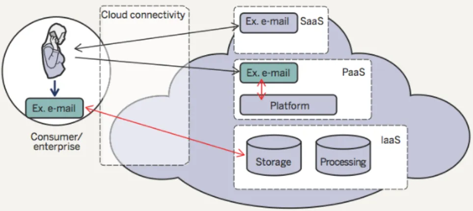
Cloud Computing is composed of three service models that meet different customer requirement (Mell et al, 2009): Software as a Service, Platform as a Service and Infrastructure as a Service. Figure 2.3.1 shows the three services infrastructure using email application as an example.
Software as a Service (SaaS) model provides to the consumer the possibility of using applications running on a cloud infrastructure. These applications can be accessed from various platforms using a thin client such as a web browser. The consumer does not control the underlying cloud infrastructure at all.
Figure 2.3.1 - Architecture of Cloud Computing with an email application (Gabrielsson et al, 2010)
Platform as a Service (Paas) gives the possibility to the consumer to deploy onto the cloud consumer-created applications using programming languages tools supported by the cloud provider. The consumer does not control the underlying cloud infrastructure but has control over the deployed applications and sometimes application hosting environment configurations as well.
Infrastructure as a Service (IaaS) allows the consumer to provision processing, storage, networks and other fundamental computing resources where it can run arbitrary operating systems and applications. The consumer does not control the underlying cloud infrastructure but has control over operating systems, storage, deployed applications and selected networking components (host firewalls…).
2.3.3 Deployment of Cloud Computing
There is four deployment models of cloud computing (Mell et al, 2009). Their differences lie primarily in the scope and access of the cloud services, as they are presented to service consumers.
• Private cloud: the cloud infrastructure is operated for a single
organization. The cloud may be managed by the organization itself or a third party and may be located in or out the organization network.
• Community cloud: the cloud infrastructure is shared by multiple related
organizations participating in a common domain that has shared concerns. It may be managed by the organizations or a third party and may exist on premise or off premise.
• Public cloud: the cloud infrastructure is made available for the public
and is owned by an organization selling cloud services.
• Hybrid cloud: the cloud infrastructure is composed of two or more
clouds (public, private or community clouds) that remain unique entities but are bound together by proprietary technology enabling portability of data and applications.
2.3.4 Economics of Cloud Computing
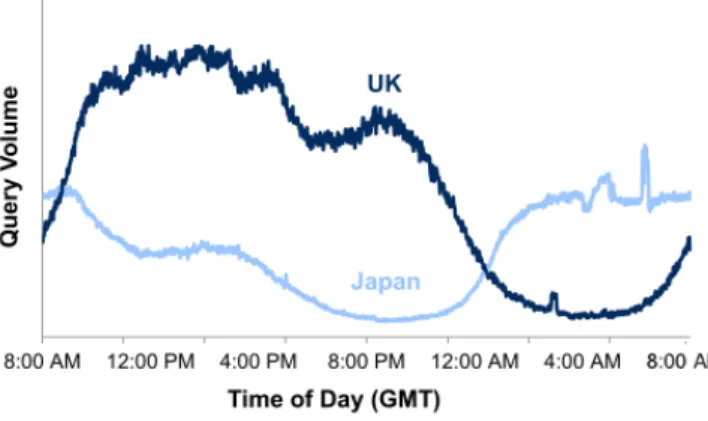
From an economical point of view, cloud computing is a cost-saving technology as it is an on-demand service. For example, cloud computing permits to efficiently match the resources of a datacenter with the peak loads it could encounter at very precise time of the day (Figure 2.3.2). It is much more cost saving than buying a powerful datacentre that will be underutilized most of the time (Harms et al, 2010). Another example to illustrate the efficiency of the on-demand service is the uncertain growth problem that startups can face when they need to invest well in advance before actually knowing their demand of infrastructure. In this case, cloud computing helps mitigate the cost of a lower-than-anticipated demand.
Due to the utilization of virtualization in cloud computing, it is possible to greatly reduce hardware cost as multiple applications or machines run on the same physical hardware, and thus to also save energy cost. In fact, the cost of power is the largest element of total cost of ownership in large facilities (Bailey, 2009). The Dell IT group found that three quarters of their servers did not exceed 20 percent of processor utilization. By virtualizing more than 5000 servers for a more intelligent and efficient resource usage, Dell saved an estimated US$29 million on new hardware purchases, reduced storage and power consumption (Brooks, 2008). It also permitted to ease management as it reduced the deployment of applications of 45 days to only 4 days.
2.4 Network Security
2.4.1 Firewalls
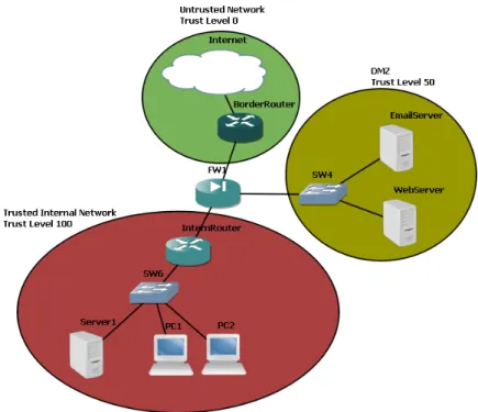
Firewalls are software or hardware devices designed to control the data flowing between two different networks (Bellovin et al, 1994; Wool, 2006). They permit or deny network transmissions based upon a set of rules. Networks firewalls can be deployed in various different network topologies depending on the requirements of the organization and its users. Typically, they are deployed on the perimeter of an organization network where it connects with the outside network, or Internet (Macfarlane, 2010). They can also be placed between internal networks to protect critical resources such as servers or databases. One of the most common network topology involving a perimeter firewall is made of three zones (Figure 2.4.1).
Figure 2.4.1 - Typical network infrastructure
The Untrusted network is the network that directly faces the Internet. The Demilitarized Zone (DMZ) is a neutral zone between the inside private network and the outside public network. It is typically a zone where servers that needs to be accessed publicly (Web server, Email server…) are deployed. This way if a server gets compromised, the internal organization network remains secured (Microsoft, 2004). The Trusted network is the internal private network. Depending on the needs of the organization, some parts of the internal network may be more trusted than others.
Several types of firewall technologies are available. Their capabilities depend on the OSI layers they are able to examine (Scarfone, 2009). There are four main types of network firewalls: stateless, stateful, application and application-proxy firewalls.
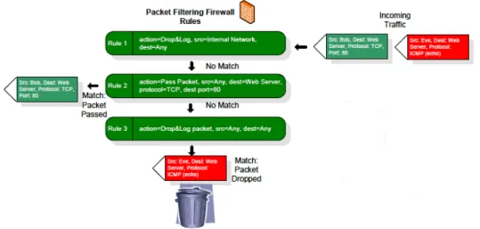
Stateless inspection firewalls operate at both the layer 3 and 4 of the OSI model (network and transport layers) and filters each packet based on information contained in the packet itself, such as source and destination IP addresses or port numbers (Figure 2.4.2). They do not keep track of the state of each flow that passes through the firewall. Stateful inspection firewalls improve the functions of packet filters by tracking the state of connections of each flow that passes through the firewall. If a connection is permitted by an existing firewall rule, they keep track of it in a state table. Then, each new packet is compared to the state table and allowed through if they are part of an open connection. Application protocol inspection (or deep packet inspection) firewalls are an extension of the stateful firewalls. They operate at the layer 3, 4 and 7 of the OSI model (network, transport and application layers) and provide protection to applications and services. They compare the protocols behaviour with defined standards that they should follow, preventing any misuse of commands in a protocol. They can also check if the protocol is what it says it is which permit to block hidden or tunnelled attacks (Macfarlane, 2010). Application-proxy firewalls operate at all the layers of the OSI model. These firewalls contain a proxy agent that acts as an intermediary between two hosts that wish to communicate. They offer the greatest level of security of all the different types of firewall but spend much more time filtering packets because of the full packet awareness.
2.4.2 Network firewalls in cloud environment
Virtualization is both an opportunity and a threat (Lin, 2009). In fact, collapsing multiple servers into a single one with several virtual machines inside results in eliminating all firewalls and other protections in existence prior to the virtualization (Ben-Efraim, 2011). Traditional physical security measures literally become blind to traffic between virtual machines since the virtual network traffic may never leave the physical host hardware (Figure 2.4.3).
Figure 2.4.3 - Physical firewall blind to the virtual traffic
There are two approaches to secure virtual network traffic using existing methods. The first one involves routing the entire virtualized network traffic out of the virtual network and onto the physical network using VLANs, where a physical firewall permits to secure, log and monitor the virtual traffic before it is routed back onto the virtual network. This solution not only introduces latency and performance degradation, it also requires complex networking to support resource pooling and live migration (Ben-Efraim, 2011).
The second approach focuses on taking software-based firewalls and running them as agents on each virtual machine. This method falls short as well, as it contains too many drawbacks: poor performance, low security level and difficulty of management – especially as the number of VMs on the virtual network increases (Moore, 2008). This is why virtual firewalls are the best answer to the security issue in virtualized environment.
2.4.3 Virtual Firewalls
A virtual firewall is a firewall service running in a virtualized environment and providing the usual packet filtering and monitoring services that a physical firewall would provides (Scarfone, 2009). We can distinguish two types of virtual firewalls:
• Virtual switch with additional security capabilities. Also referred to
• Virtual firewall operating in hypervisor-mode with a managed kernel
process running on the host hypervisor that sits atop all virtual machines activity.
Virtual firewall in bridge-mode acts like its physical-world firewall analog. Positioned in a strategic point of the virtual network infrastructure (usually between different networks), it can intercept virtual traffic destined for other segments. Because a bridge-mode virtual firewall once installed is then a virtual machine itself, its relationship to the other virtual machines may become complicated over time because of virtual machines migration allowed by the virtualized infrastructure. An example of this type of product is Cisco Nexus 1000v.
By contrast, a virtual firewall operating in hypervisor-mode is not actually part of the virtual network at all. A hypervisor-mode virtual firewall is located in the virtual machine monitor (VMM) where it can capture virtual machine activity, including packet injections. Since a hypervisor-mode virtual firewall is not part of the network and is not a virtual machine, its functionalities cannot be monitored or altered by users and software having access to the virtual network. Hypervisor-mode virtual firewalls can be much faster in term of throughput than the same technology running in bridge-mode because they are not doing packet inspection in a virtual machine, but rather from within the kernel at native hardware speeds (Juniper, 2011). An example of this type of virtual firewall is Reflex Systems vTrust.
2.5 Network Security Threat
Because this thesis will focus on the evaluation of firewalls, which are supposed to filter and block attacks, some network threats will be looked at in this section. As there are so many kinds of threats, only the most common ones will be presented.
2.5.1 Viruses, Worms and Trojans
Viruses, worms and trojans are all considered malicious software or malicious code. The NIST (1995, p. 27) describes these three types of malicious software as the following:
• A virus is a segment of code that get attached itself to an existing
executable (an application) and is executed when the user runs the contaminated application. Usually, viruses carry out malicious actions such as overwriting or deleting data.
• A worm is a self-replicating program that does not need to be attached
to a host program. No user intervention is required for the worm to run and replicate itself before it tries to propagate to other host systems throughout a network.
legitimate one. Once executed, it will carry out malicious actions such as opening a backdoor (opening a port) on the host allowing outside access to that machine.
2.5.2 Network Scanning
The purpose of network scanning is to gather information about a network (Wagh, 2009) such as network addresses and open network ports. This threat is usually the first step an intruder takes before actively attacking a network (Buchanan, 2011).
The most common scanning techniques are ping sweep, port scan and port sweep. Ping sweep refers to the scanning of a wide range of network addresses on a given subnetwork and aims at knowing which machines are responsive, and thus running, on a network. Port scan technique refers to the scanning of TCP ports for a range of hosts on a given subnetwork in order to find out what ports are open on the host machines. Port sweep is very similar to port scan, but focuses instead on specific ports rather than scanning every one of them. One of the most famous programs that permits network scanning is Nmap (Lyon, 2011).
2.5.3 User Privilege Gain
This type of threat consists of gaining a foothold on a network. Usually it involves obtaining access to a low-level user account by guessing of login and passwords using techniques such as brute force dictionary attacks. Once on the system, an intruder will try to move up through the privilege hierarchy (Buchanan, 2011) using for example software flaws to exploit weaknesses, where in some case a program would not properly identify the requester. The ultimate goal of a user privilege gain attack is to obtain the highest level of access such as an administrator or root account. If an intruder manages to gain access to such an account, he becomes in control of the entire system. One of the most famous dictionary attack program is Hydra (THC, 2011). It supports many different services such as SSH, FTP or HTTP. In this type of attack, the program attempts to gain access to a target using user name and password lists trying all possible combinations (Shirey, 2007).
2.5.4 Denial of Service Attacks
A denial of service (DoS) attack consists of flooding a target with continual requests for services, which eventually reduces its performance (Buchanan, 2011). It exists various types of carrying out DoS attack, but the three main ones that remains a serious threat nowadays are smurf attack, flood attack and SYN attack (Georgieva, 2009).
With a smurf attack, also called ICMP flood, the attacker sends an ICMP echo request to a broadcast address with the source address of the echo request being the IP address of the victim. The attacker target a server within the
victim’s network that will broadcast the ICMP echo request throughout the entire network resulting in all the network’s machines returning a response. SYN attacks exploit a weakness in the TCP/IP handshaking mechanism, which is the state retention TCP performs for some time after receiving a SYN request on an open port. If an attacker floods the target with SYN messages, the SYN buffer will quickly get full not allowing new legitimate connections to be established (Eddy, 2007).
Flood attack is one of he first form of DoS attack and its mechanism is simple, it consists of sending more traffic to a server than it can handle. This type of attack can only succeed if it uses Distributed Denial of Service (DDoS) attack. A DDoS attack uses multiple computers to send out requests to the target. The attack is generally controlled by a single computer (Master) which communicates with a network of infected machines which have a bot installed on them to initiate the attack. These networks of infected machines are known as botnets (Nazario, 2008).
2.6 Methodologies in Evaluating Firewalls
2.6.1 Evaluation Metrics
A metric is a measurement taken over a period of time that communicates vital information about a process or activity. Units of measurement can include counts, frequency, percentages or physical values (Cambra, 2004). In the work of Kean and Mohd (2002), the authors propose a benchmarking methodology to evaluate firewall performance using three distinct metrics: throughput, latency and goodput:
• Throughput is the maximum rate at network layer which none of the
received packet is dropped by the firewall without activating filtering rules. The measurement unit is input packets per second.
• Latency is the time interval starting when a packet enters the firewall
and ending when this same packet leaves it. It is measured in seconds.
• Goodput is the rate at which packets are forwarded to the right
destination interfaces of the firewall without taking into account packets dropped due to filtering rules. The measurement unit is in bit or packets per second.
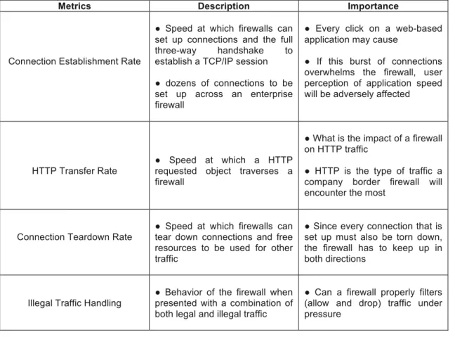
In the recent work of Snyder (2010) based on the IETF’s RFC 3511 (Hickman et al, 2003), throughput and latency are also highlighted for being critical metrics to evaluate firewall performance. However the author introduces four new evaluation metrics to meet today’s application requirement: Connection Establishment Rate, Concurrent Connection Capability, HTTP Transfer Rate and Connection Teardown Rate (Table 2.6.1).
Metrics Description Importance
Connection Establishment Rate
● Speed at which firewalls can set up connections and the full three-way handshake to establish a TCP/IP session ● dozens of connections to be set up across an enterprise firewall
● Every click on a web-based application may cause
● If this burst of connections overwhelms the firewall, user perception of application speed will be adversely affected
HTTP Transfer Rate ● Speed at which a HTTP requested object traverses a firewall
● What is the impact of a firewall on HTTP traffic
● HTTP is the type of traffic a company border firewall will encounter the most
Connection Teardown Rate ● Speed at which firewalls can tear down connections and free resources to be used for other traffic
● Since every connection that is set up must also be torn down, the firewall has to keep up in both directions
Illegal Traffic Handling ● Behavior of the firewall when presented with a combination of both legal and illegal traffic
● Can a firewall properly filters (allow and drop) traffic under pressure
Table 2.6.1 - Additional Firewall performance evaluation metrics (Snyder, 2010; Hickman et al, 2003)
As a firewall is supposed to block attacks (if it is properly configured), it is critical to evaluate the illegal traffic handling of a firewall (Hickman et al, 2003). Illegal traffic does not mean necessarily attack traffic, but traffic that is not allowed to pass the firewall. However, this can also be done with real attack traffics making the evaluation closer of a real-life scenario.
Because the aim of this thesis will be the evaluation of a virtual firewall, its hardware resource won’t be dedicated. It would be interesting to record hardware consumption metrics at different workload level of the firewall, such as CPU or memory usage, to get an idea on its resource consumption impact. Virtualization and cloud computing are considered green computing technologies that permit to save energy consumption (Das et al, 2010). Therefore, another interesting metric to record in parallel with the evaluation of a virtual firewall would be the power consumption of the physical device where the firewall is being virtualized. This can be done using a simple wattmeter plugged into the device we want to monitor (Bluejay, 2011).
2.6.2 Black-Box and White-Box Testing
Before starting to analyse the many different evaluation methods proposed by researchers over the past few year, it is important to understand the very first concept of evaluation. There is two predominate testing methodologies:
black-box and white-black-box testing (TestPlant, 2011).
Black-box testing looks at the available inputs and at the expected outputs of an entity without any concerns with its inner workings. The main advantage of this technique is its ease of use as the testers do not have to bother with the internal workings of the entity. This strength is also a weakness as it is often criticised that black-box testing lack of introspection (TestPlant, 2011). On the contrary, White-box methodology looks at the inner workings of the entity it tests and can even interact with them. This technique permits much more introspection that black-box testing but also adds additional complexity to the evaluation.
These two testing techniques are more commonly used in software engineering but can still be applied to firewall evaluation. In the work of Hafele (2004), the author applies black-box and white-box testing to ethical hacking. The black-box approach is depicted as an attack on network with little or no knowledge concerning the targeted network and is very similar to what criminal hackers would do in real life during the initial phase of an attack. The white-box approach gives much more information to the hacking team prior to the penetration test so there will be fewer unknowns or variables.
It can be summarised that there is no “best” technique between this two methodologies for evaluating firewall. In fact, some tests depicted in the previous part (2.6.1) like latency or IP throughput fall in the category of black-box testing where it does not matter to know what are the filtering rules of the firewall and instead simply looks at the input and output of the firewall. Some other tests such as goodput are closer to white-box testing as it requires to know the filtering rules of the firewall so the traffic can be matched to them in order to successfully provide specific amount of legal traffic.
2.6.3 Real-time and Offline Evaluation
There are two different approaches to network device evaluation: “the use of canonical packet traces for offline tests or traffic generation systems for online evaluation (Sommers et al, 2005)”.
• Real-time (or Online) evaluation involves live traffic generation. An
application like Harpoon will be used to generate real traffic that will be sent to the network device.
• Offline evaluation involves playing back sets of data rather than live
traffic. These sets of data may be captured using sniffer programs like Wireshark and then played back with tool such as Tcpreplay.
The following sections will look at well-known evaluation methods. DARPA and Automated evaluation are both based on offline evaluation while LARIAT and Trident are real-time evaluation.
2.6.4 DARPA Evaluation
Created by the MIT Lincoln Laboratory in sponsorship with the Defense Advanced Research Projects Agency (DARPA) and the Air Force Research Laboratory (AFRL/SNHS), the DARPA evaluation is one of the first evaluation methods for computer network intrusion detection systems. Even if this evaluation method was designed in the first place to evaluate Network Intrusion Detection System (NIDS), it is also applicable to firewalls (Kayacik et al, 2001). The main goal of the DARPA evaluation was to evaluate a set of IDSs in term of detection and false alarm generation while providing the computing community with data sets that could be used by others for evaluating their IDSs (Lippmann et al, 2000). To do that, the MIT Lincoln Lab built a small network simulating an Air Force base connected to the Internet and then produced background traffic with scripts while injecting attacks at certain periods of time (Brugger et al, 2007). The overall traffic was recorded into data sets for later offline evaluation. The datasets were first release in 1998 and contained seven weeks of training data and two weeks of testing data, both containing network-based attacks in the midst of normal background data. The four main attack types present in the DARPA evaluation are denial of service, probing, remote to local and user to root (Lippmann et al, 2000). In 1999, a second data set based on the 1998 one was produced containing additional new inside attacks and new stealthy attacks.
One of the major critics of the DARPA evaluation is that the data sets traffic is too different from real traffic. The work of Mahoney and Chan (2003) compares the DARPA 1999 dataset with real traffic and point out many irregularities. The main ones are:
- TCP SYN regularity: always the same 4 options bytes whereas there are 103 different options in the collected real traffic
- Source address predictability: only 29 different source addresses appear in the DARPA dataset traffic against 24,924 in the real data - Packet header field regularity: only 9 different TTL values and 4 TOS
values in the dataset against 177 TTL values and 44 TOS values in the real data
Also, it is important to point out that the DARPA evaluation was created more than 10 years ago now, therefore it does not cover the many new security threats that emerged since then, making this evaluation methodology not as relevant as we could have imagine in the first place.
2.6.5 Automated Evaluation
To address some of the DARPA evaluation shortcomings, we must look at a more recent evaluation methodology carried out by Massïcotte, Gagnon, Labiche, Briand and Couture (2006). Their work focuses on giving a more up to date data set for evaluating IDS along with a tool that automatically analyse and evaluates IDS.
The automated evaluation proposed is based around two elements: a Virtual Network Infrastructure (VNI) that is able to generate a data set of attacks, and a Intrusion Detection System Evaluation Framework (IDSEF) that analyses the alerts generated by the IDSs being evaluated.
Because the main dissertation of this thesis is the evaluation of virtual firewalls and not IDSs, only the dataset part of this evaluation methodology can be useful. However, the VNI does not generate any background traffic but instead only attack traffic (Massïcotte et all, 2006). Because the evaluation metrics described in previous section (2.6.1) require background traffic as well as illegal traffic, this evaluation method alone does not suit the goal to be achieved in this dissertation.
2.6.6 LARIAT Evaluation
The Lincoln Adaptable Real-time Information Assurance Testbed (LARIAT) is an extension of the testbed created by the DARPA evaluation with two objectives in mind (Rossey et al, 2002): support real-time evaluations, and create deployable, configurable and easy to use testbed.
To meet the second objective, LARIAT was designed using a GUI interface called network director where testers can interact through menus and buttons rather than command lines. The LARIAT evaluation itself is carried out by emulation of both background and attack traffic generated in real-time and not just played back from a dataset (Rossey et al, 2002). The traffic profiles were based on the network traffic distribution of a US military base, but new traffic profiles can be added to suit a particular network environment. The tester can choose through the GUI the type of background traffic to be generated (HTTP, FTP and so on) along with the traffic rate and the distribution of each service over the course of a day. The types of attacks to be carried out are chosen by the users in a similar fashion.
Like DARPA, LARIAT was mainly designed for evaluating IDS. However, the evaluation methodology is also applicable to firewalls, routers and VPNs (Rossey et al, 2002). The only major issue with LARIAT is that it is part of a US Government funded project and not available for public use (Athanasiades et al, 2003).
2.6.7 Trident Evaluation
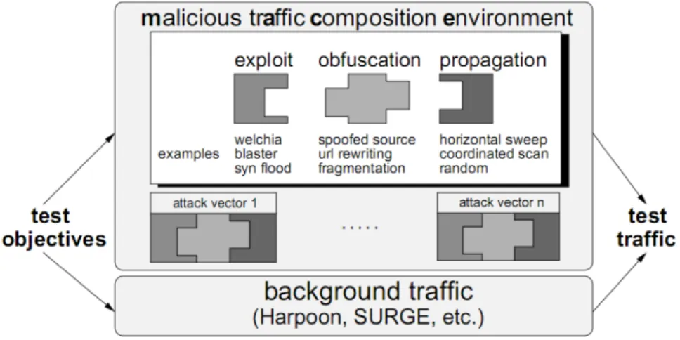
Trident is a traffic generation framework made for the evaluation of NIDS or other network systems, such as firewalls (Sommers et al, 2006). The main capabilities of Trident are:
• Generation of background (or benign) traffic streams, including
payloads. This is done by Harpoon, a background traffic generator.
• Generation of new types of malicious traffic. This is done using the
Malicious Traffic Composition Environment (MACE), which is a modular attack composition framework. MACE consists of three
components: exploit, obfuscation and propagation (Figure 2.6.1).
• Modulation of both the background and malicious test traffic in term of
mixture, volume and temporal arrival.
Figure 2.6.1 - Trident Framework (Sommers et al, 2004)
MACE supports 21 types of attacks such as SYN flood or smurf attacks, and has the capability to play back 58 of the attacks used in the DARPA evaluation (Sommers et al, 2006). Harpoon presents two main features (Sommers, 2005) which are the ability to generate network traffic at the IP flow level, and to be easily configured to automatically create traffic identical to traffic measured in specific network topologies using NetFlow traces.
The Trident framework successfully generates background and malicious traffic in a realistic way and allows a fine control to the testers over the traffic generation. However, one of the critics against the Trident evaluation is that the background traffic generated by Harpoon is not realistic enough as it uses always the same port number for its communication (Corsini, 2009).
2.7 Conclusion
Section 2.2 described the meaning and functioning of virtualization. It showed the different types of virtualization on the market in term of architecture and hypervisor approach. It also highlighted the link existing nowadays between virtualization and computer processors.
Section 2.3 defined the concept of cloud computing and described the different types of cloud infrastructure in use. It showed the obvious economical benefits of such a technology, permitting organizations to drastically reduce their costs in term of hardware acquisition or power consumption. It is mainly the cost saving aspect of this technology that makes cloud computing so widely used nowadays, making the question of security in cloud environment even more critical.
The main purpose of firewalls was explained in Section 2.4 along with a description of the different firewall types existing. The security issue in virtualized environment with physical firewalls being blind to the virtual traffic
was pointed out, and some solutions to this problem such as virtual firewalls were presented. One possible solution is to route the entire virtual traffic to a physical firewall using VLANs before routing it back in the virtualized environment, but this technique greatly increase the overall latency of the network.
Section 2.5 analysed some of the main network security threats that both organizations and personal users face. These threats which are already a serious concern for physical networks, are even more dangerous in virtual networks where security is too often neglected. Denial of Service attacks are particularly virulent and difficult to prevent.
Finally, Section 2.6 reviewed the different methodologies used to evaluate firewalls: DARPA evaluation, Automated evaluation, LARIAT evaluation and Trident evaluation. All these evaluation methods pointed out the importance of choosing a proper methodology, and also highlighted the importance of having both legal and illegal traffic in order to make the evaluation viable. Different works were also looked at in order to introduce a set of metrics to evaluate firewall performances. The most used are IP throughput, Latency and Goodput.
The main aim of this thesis is to provide an evaluation of a virtual firewall in a cloud environment. Based on the findings in this literature review, we can identify three key requirements:
1. Choice of a cloud infrastructure
2. Choice of meaningful evaluation metrics 3. Use of a proper evaluation methodology
To provide an effective evaluation of a virtual firewall, it will be required to meet all those three requirements. The next chapter will describe the design choices that are required to set up such an evaluation.
3 Design
3.1 Introduction
The literature review concluded that the three key requirements to evaluate a virtual firewall in a cloud environment were:
1. Choice of a cloud infrastructure
2. Choice of meaningful evaluation metrics 3. Use of a proper evaluation methodology
This chapter introduces the design involved in such an evaluation. First, the cloud infrastructure choice and why it was chosen will be outlined (Section 3.2). Then the virtual firewall used in this cloud infrastructure will be descripted along with the basic set of filtering rules it will present (Section 3.3).
Section 3.4 will then focuses on the evaluation methodology and on the different evaluation metrics that will be chosen to evaluate the virtual firewall. For each evaluation metric, the overall design of the experiment will be detailed. Section 3.5 will present the different tools that will be used during the evaluation of the virtual firewall. Finally, Section 3.6 will provide a conclusion to this chapter.
3.2 Cloud infrastructure
In order to evaluate a virtual firewall in a cloud environment, it is required to choose a cloud platform where the evaluation will take place. For simplicity reasons, it was chosen to implement a cloud infrastructure only using open source solutions. By doing so, it becomes quite easy to install and set up the entire cloud platform without having to worry about cost or copyright issues. Also, using an open source platform for the evaluation makes any future work or improvement based on this dissertation much easier. It was chosen to use Xen as a hypervisor and OpenNebula as a cloud toolkit.
Xen is one of the most famous open source virtualization solutions. The Xen Hypervisor is a thin software layer that runs directly on computer hardware replacing the operating system. It allows the computer hardware to run multiple guest operating systems (virtual machines) securely and independently. The machine running Xen hypervisor contains three components (Xen, 2011):
• Xen Hypervisor
• Domain0, the privileged domain. It is a privileged guest running on the
hypervisor with direct hardware access and guest management responsabilities
• Multiple DomainU, the unprivileged domain guests that runs on the
which are launched and controlled by the Domain0, run with special modified OSs (paravirtualization) or with unmodified ones using hardware-assisted virtualization. As an example, Windows machines can only be virtualized using hardware-assisted virtualization.
OpenNebula is an open source cloud toolkit that permits to build and manage any type of cloud Infrastructure. It can interact with multiple different hypervisor such as Xen, KVM, or VMWare ESX (OpenNebula, 2011). For ease of evaluation, it will be used to implement a private cloud so both clients and virtual machines will be localised on the same site.
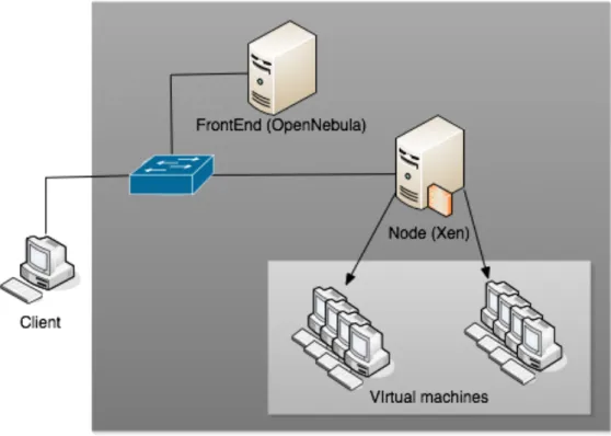
In order to implement a private cloud infrastructure, two machines will be required: a frontend and a node. The frontend is used to install the cloud toolkit (OpenNebula) while the node is used to install the Xen hypervisor in charge of the virtual machines. The operating system of these machines will be OpenSUSE as it fully supports Xen and OpenNebula. In term of hardware requirement, the node should presents high CPU performance in order to support virtualization. Also, its processor should support virtualization (AMD-V or Intel-VD processor). Once the platform will be in place, Linux and Windows images will be installed on the node using Xen and deployed for users using OpenNebula. The overall scheme of the cloud infrastructure is shown in Figure 3.2.1.
Iptables -P INPUT REJECT Iptables -P OUTPUT ACCEPT iptables -P FORWARD REJECT
iptables -A FORWARD -i eth0 -o vif1.0 -j ACCEPT iptables -A FORWARD -i vif1.0 -o eth0 -j ACCEPT
3.3 Virtual Firewall
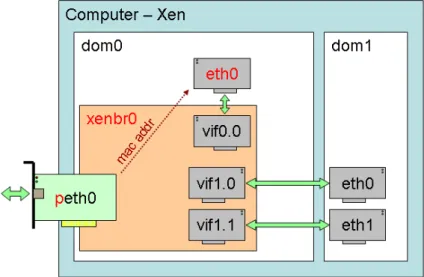
Xen Hypervisor can only be installed on Unix-like operating systems and therefore fully supports the use of linux firewall (iptables). Once the Xen Hypervisor installed, the privileged domain (dom0) is not only responsible of the guest management but also of bridging the different unprivileged domain (domU) to him. For each new domU instance, Xen creates a new pair of connected virtual ethernet interfaces with one end in dom0 and the other in domU (Figure 3.3.1). Therefore, by using iptables commands, the Xen Hypervisor becomes a virtual switch with additional security capabilities: a bridge-mode virtual firewall.
Figure 3.3.1 - Xen Network-bridging (XenNetworking, 2011)
The linux firewall also referred to as iptables, uses IP addresses, protocols and ports to filter network traffic; it can also track the state of connections of the flows that pass through him and therefore is considered as a stateful inspection firewall. It presents four different predefined tables to which filtering rules can be added. The main three ones are:
• INPUT: packets destined to be locally delivered • OUTPUT: packets originating from the machine itself
• FORWARD: packets neither destined for or originating from the host,
but passing through the machine. This is the table that will be mostly used as Domain0 acts like a bridge mainly forwarding packets to the other DomainU.
Taking the example in Figure 3.3.2, we can identify the following:
• -P command change the policy of the chain target. Here, the INPUT
and FORWARD chains are set to reject any packets while the OUTPUT chain accept any packets
• -A command permits to append to a chain. Here, the FORWARD chain
is appended so packets coming on the in-interface eth0 (physical network interface) and being forwarded to the out-interface vif1.0 (virtual network interface) get accepted, and the other way around
• This set of rules completely block the access to the physical host and
only allow traffic to and from the virtual host vif1.0
Filtering rules will be created in accordance with the evaluations to be carried out. For example to test illegal traffic handling, it will be crucial to add proper rules blocking the “illegal” traffic.
3.4 Evaluation Scenarios
Different evaluation metrics to test firewalls were studied in the literature review. It was chosen to use five specific metrics: IP throughput, latency, goodput, HTTP transfer rate and denial of service handling. These metrics will permit to evaluate the performances of the implemented virtual firewall.
In term of methodology, the evaluation is a mix of both white-box and black-box testing. IP throughput or latency evaluation do not require any knowledge of the firewall configuration while goodput or illegal transfer handling are evaluation that need to be taken knowing what are the firewall filtering rules. This evaluation fall in the real-time (or online) evaluation category as it involves live traffic generation instead of playing back sets of data. However, and this will be explained in the following chapter, none of the evaluation methods involving real attack traffic will be used in our evaluation.
3.4.1 IP Throughput
IP Throughput evaluates the maximum number of packets a device can receive without dropping any. It is measured in input bits or packets per second, and the test duration should be at least 120 seconds. For an in-depth evaluation, it is also interesting to increase the frame size of the packets: 64, 128, 256, 512, 1024 and 1518 bytes (Kean and Mohd, 2002). There must be no filtering rules on the firewall. The procedure involves sending large amount of packets at a constant rate on one of the firewall interface, and then counts the number of frames received. The test is repeated until there is no packet loss.
In order to evaluate the impact of the iptables filter table on the IP throughput, the test will be run again while gradually increasing the number of filtering rules on the firewall. This will be done using three different frame sizes: 128, 512 and 1518 bytes. The filtering rules generated for this evaluation are there to simulate the worst case scenario, forcing the incoming packers to be
matched to all of theses rules before being allowed. Performance would be much better if realistic filtering rules were used.
This will be done with the network testing tool Iperf. This tool measures the IP throughput of a network by sending TCP or UDP data streams from a client to a server. To evaluate the IP throughput of the virtual firewall, the client will be installed on the client machine, which is connected to the node (Xen Hypervisor) where the Iperf server will be running. This is shown in Figure 3.4.1.
Figure 3.4.1 - IP Throughput evaluation with Iperf
The result of the IP throughput evaluation will be reported in a graph format with the X-axis being the frame sizes and the Y-axis being the aggregate IP throughput in bits per second. This test is one of the most important as the IP throughput value will be reused during later evaluation. A second graph will be displayed, with the X-axis being the number of filtering rules on the firewall and the Y-axis the IP throughput in bits per second.
3.4.2 Latency
Latency is a measure of time delay that can occur in a system. The processing delay of a firewall is the time a packet takes to enter and then leave the firewall, measured in seconds. The procedure involves sending a stream of frames at a constant rate through the firewall where tagged frames are used for timestamping. Both the times at which the tagged frame reaches the input interface and then the output interface of the firewall are recorded. The difference between these two times is the latency. The traffic should be generated over a period of 120 seconds or more (Kean & Mohd, 2002). In order to realize this test, different scenario were imagined:
- ICMP Timestamp: An ICMP Timestamp reply contains three timestamps: originate timestamp which is the time the sender last touched the message,
receive timestamp which is the time the receiver first touched the message, and transmit timestamp which is the time the receiver last touched the message before sending it back. By subtracting the transmit timestamp by the receive timestamp, we get the processing latency of the packet (Hall, 2000). The problem of this scenario is that the time measured is in milliseconds which is not precise enough as the latency generated by the firewall is less than 1ms (at lest with very few filtering rules).
- ICMP Echo/rReply: normal ping ran at two different times with the firewall on, and then off. The firewall latency would be the difference between these two times, divided by