A NEW FORMULATION FOR THE ANALYSIS OF BONDED ELASTIC LAYERS
A THESIS SUBMITTED TO
THE GRADUATE SCHOOL OF NATURAL AND APPLIED SCIENCES OF
MIDDLE EAST TECHNICAL UNIVERSITY
BY
SEVAL PINARBAŞI
IN PARTIAL FULFILLMENT OF THE REQUIREMENTS FOR
THE DEGREE OF DOCTOR OF PHILOSOPHY IN
CIVIL ENGINEERING
Approval of the Graduate School of Natural and Applied Sciences
______________________ Prof. Dr. Canan Özgen
Director
I certify that this thesis satisfies all the requirements as a thesis for the degree of Doctor of Philosophy.
_______________________ Prof. Dr. Güney Özcebe
Head of Department
This is to certify that we have read this thesis and that in our opinion it is fully adequate, in scope and quality, as a thesis for the degree of Doctor of Philosophy.
______________________ Assoc. Prof. Dr. Uğurhan Akyüz
Supervisor
Examining Committee Members
Prof. Dr. Polat Gülkan (METU,CE)__________________ Assoc. Prof. Dr. Uğurhan Akyüz (METU,CE)__________________ Prof. Dr. Yalçın Mengi (METU,ES)__________________ Assoc. Prof. Dr. Ahmet Yakut (METU,CE)__________________ Assist. Prof. Dr. A. Hakan Argeşo (Baskent Unv., ME)__________________
I hereby declare that all information in this document has been obtained and presented in accordance with academic rules and ethical conduct. I also declare that, as required by these rules and conduct, I have fully cited and referenced all material and results that are not original to this work.
Name, Last Name: Seval Pınarbaşı Signature :
ABSTRACT
A NEW FORMULATION FOR THE ANALYSIS OF
BONDED ELASTIC LAYERS
Pınarbaşı, Seval
Ph. D., Department of Civil Engineering Supervisor: Assoc. Prof. Dr. Uğurhan Akyüz
April 2007, 248 pages
Elastic layers bonded to reinforcing sheets are widely used in many engineering applications, e.g., as elastic foundations to machinery, as seismic isolators to structures, etc. Because of its practical importance, the behavior of bonded elastic layers under some basic deformation modes (e.g., compression, bending and shear modes) has attracted the attention of many researchers. However, the analytical works available in literature involve, with the object of obtaining design formulas, many simplifying assumptions. In this dissertation, a new formulation is developed for the analysis of bonded elastic layers, which removes most of the assumptions used in the earlier formulations. Since the displacement boundary conditions are included in the formulation itself, there is no need to start the formulation with some assumptions on stress and/or displacement distributions
or with some limitations on geometrical and/or material properties. For this reason, the solutions derived from this formulation are valid not only for “thin” layers of strictly/nearly incompressible materials but also for “thick” layers and/or compressible materials.
The advanced solutions obtained within the framework of the new formulation are used to study the behavior of bonded elastic layers under basic deformation modes. The effects of three key parameters, shape factor, Poisson’s ratio and reinforcement flexibility, on effective layer moduli, displacement/stress distributions, and location/magnitude of maximum stresses are investigated. It is shown that the stress assumptions of the “pressure” method are inconsistent with the results obtained for thick layers and/or compressible materials and/or flexible reinforcements, and that the assumption “plane sections remain plane” is not valid, in general.
Keywords: Bonded Elastic Layers, Elastomeric Bearing, Seismic Isolation, Shape Factor, Poisson’s Ratio
ÖZ
ÜST VE ALT YÜZEYLER
İ
NDEN YAPI
Ş
TIRILMI
Ş
ELAST
İ
K TABAKALARIN ANAL
İ
Z
İ
İ
Ç
İ
N YEN
İ
B
İ
R
FORMÜLASYON
Pınarbaşı, Seval
Doktora, İnşaat Mühendisliği Bölümü Tez Yöneticisi: Doç. Dr. Uğurhan Akyüz
Nisan 2007, 248 sayfa
Üst ve alt yüzeylerinden güçlendirici plakalara yapıştırılmış elastik tabakalar, elastik makina temelleri ve sismik yapı izolatörleri gibi pek çok mühendislik uygulamasında yaygın olarak kullanılmaktadır. Pratik önemi nedeni ile, güçlendirilmiş elastik tabakaların bazı temel deformasyon modları (basınç, eğilme ve kayma modları gibi) altındaki davranışları bir çok araştırmacının dikkatini çekmiştir. Ancak, literatürde konu ile ilgili mevcut analitik çalışmalar, tasarım formülleri elde edilmesi amacı ile, bir çok basitleştirici kabul içermektedir. Bu tezde, güçlendirilmiş elastik tabakaların bazı temel deformasyon modlarındaki davranışlarının analizi için yeni bir formülasyon geliştirilmiştir. Bu formülasyon, daha önceki çalışmalarda kullanılan kabüllerin pek çoğunu elimine etmektedir.
Deplasman sınır koşulları formülasyonun içinde yer aldığı için analize, tabakadaki gerilme ve/veya deplasman dağılımları üzerine bazı varsayımlar yapılarak ya da tabakanın geometrik ve/veya malzeme özelliklerine bazı sınırlandırmalar getirilerek başlanması gerekmemektedir. Bu nedenle, bu formülasyondan elde edilen çözümler sadece sıkıştırılamaz ya da sıkıştırılamaza yakın malzemelerden üretilen “ince” tabakalar için değil sıkıştırılabilir malzemelerden üretilen “kalın” tabakalar için de geçerlidir.
Yeni formülasyon çerçevesinde elde edilen ileri çözümler, güçlendirilmiş elastik tabakaların temel deformasyon modlarındaki davranışlarının incelenmesinde kullanılmıştır. Analizlerde, üç anahtar parametrenin, tabakanın şekil faktörü, malzemenin Poisson oranı ve güçlendirici plakaların rijitliklerinin, etkili tabaka modülleri, tabakadaki deplasman ve gerilme dağılımları ile tabakada oluşan maksimum gerilmelerin yer ve büyüklüğü üzerindeki etkileri incelenmiştir. Kalın tabaka ve/veya sıkıştırılabilir tabaka ve/veya esnek donatı durumları için elde edilen sonuçların yaygın olarak kullanılan basınç metodundaki gerilme varsayımları ile tutarsız olduğu kanıtlanmış; “düzlem kesitler düzlem kalır” varsayımının genel olarak geçerli olmadığı gösterilmiştir.
Anahtar Kelimeler: Güçlendirilmiş Elastik Tabakalar, Elastomerik Yastık, Sismik İzolasyon, Şekil Faktörü, Poisson Oranı
ACKNOWLEDGEMENTS
I would like to express my deepest gratitude to all –not only to those whose names are listed below which are, in fact, extremely lucky to come to my little brain– who gave me their support, encouragement and, most importantly, their love which made it possible for me to accomplish this dissertation. Thank you all for being in my life and please stay there forever…
Specially, my sincere appreciation and gratitude go to my supervisor, Dr. Uğurhan Akyüz, who gave me the freedom to pursue my own research interests.
It is really hard to find the proper words to be able to express my appreciation to Dr. Yalçın MENGİ, whose contribution to the entire work is invaluable. However, I can easily say one thing: This dissertation could not have been completed without his guidance…
I would also like to thank to the other members of my dissertation committee: Dr. Polat Gülkan and Dr. Ahmet Yakut, for their valuable suggestions and encouragements during my research.
This study is partially funded by the State Planning Organization (DPT) Grant No: BAP-08-11-DPT2002K120510, which is also gratefully acknowledged.
I also thank Mr. Burhan Avcı and the staff of the Structural Mechanics Laboratory for their help during the realization of the tests, which constituted one stage of my Ph.D. studies.
I would like to extend my gratitude to Prof. James M. Kelly for giving me the opportunity to work with him at the Earthquake Engineering Research Center of the University of California at Berkeley. It was a great privilege for me to study under the supervision of my “idol”.
Special thanks go to Yalın Arıcı and Barbaros Sarıca for helping to start my Berkeley adventure, and to my home mate Çağla Meral for sharing not only her home but also her life and love. I would also like to express my gratitude to Nergiz Dinçer, Dimitrios Konstantinidis, İsmail Ergen, Tufan Karalar, Afşin Sarıtaş, Feyzi Tecellioğlu and Türel Gür for their valuable friendship and support before/during/after my Berkeley days. My sincere appreciation also goes to Dr. Yousef Bozorgnia, Mr. Charles D. James and Ms. Nancy Nelson for their help, support and valuable friendship during my Berkeley experience.
My colleagues Burcu Erdoğan, Dilek Okuyucu, Beyhan Bayhan, Bora Acun, Serhat Bayılı, Emre Akın, Özgür Avşar, Abdullah Dilsiz, Barış Erdil, Ramazan Özçelik, and Hakan Erdoğan are also acknowledged for their friendship.
Never to be forgotten are my dearest friends; Ali Cihan Pay, Fatih Kürşat Fırat, Gökhan Özdemir, İbrahim Erdem, Metin Yılmaz, Onur Pekcan, Reyhan (Eğri) Şahin, Seçkin Çaban, Sezgin Küçükçoban and Sinan Akarsu, whose friendship, moral support and love are invaluable for me.
My heartfelt gratitude goes to three special persons in my life: Fatma (Durna) Akar, Volkan Aydoğan and Şevket Özden. Without their endless support, encouragement and love, this dissertation would not have been completed.
Finally, I would like to express my deepest gratitude to my parents, Ülker Pınarbaşı and Mehmet Pınarbaşı, my brother Ali Seyhun Pınarbaşı, and also to my aunt Ülkü Durna for their unconditional love, support and encouragement they have provided me throughout my whole life.
TABLE OF CONTENTS
ABSTRACT... iv ÖZ ... vi ACKNOWLEDGEMENTS ... ix TABLE OF CONTENTS... xi LIST OF TABLES ... xvLIST OF FIGURES... xvi
CHAPTER 1. INTRODUCTION ... 1
1.1 BONDED ELASTIC LAYERS ... 1
1.2 AIM OF THE DISSERTATION ... 5
1.3 SCOPE AND ORGANIZATION OF THE DISSERTATION... 7
2. THEORY ON BONDED ELASTIC LAYERS ... 9
2.1 ELASTIC LAYERS BONDED TO RIGID SURFACES ... 9
2.1.1 Compressive Behavior... 13
2.1.2 Bending Behavior ... 26
2.1.3 Apparent Shear Behavior... 29
2.2 ELASTIC LAYERS BONDED TO FLEXIBLE REINFORCEMENTS . 31 2.2.1 Compressive Behavior... 33
2.2.2 Bending Behavior ... 39
2.2.3 Warping Behavior... 41
3. THE NEW FORMULATION FOR THE ANALYSIS OF BONDED ELASTIC LAYERS ... 47
3.1 REVIEW OF THE APPROXIMATE THEORY USED IN THE
DISSERTATION ... 49
3.2 APPLICATION OF THE APPROXIMATE THEORY TO ELASTIC LAYERS BONDED TO RIGID SURFACES... 54
3.2.1 Derivation of Reduced Governing Equations... 56
3.2.1.1 Uniform Compression ... 56
3.2.1.2 Pure Bending ... 58
3.2.1.3 Apparent Shear ... 60
3.2.2 Reduced Governing Equations in Cylindrical Coordinates... 61
3.2.2.1 Uniform Compression ... 64
3.2.2.2 Pure Bending ... 65
3.2.2.3 Apparent Shear ... 67
3.2.3 Determination of Displacement/Stress Distributions ... 68
3.2.4 Compression, Bending and Apparent Shear Moduli ... 69
3.3 APPLICATION OF THE APPROXIMATE THEORY TO ELASTIC LAYERS BONDED TO FLEXIBLE REINFORCEMENTS ... 71
3.3.1 Derivation of Reduced Governing Equations... 73
3.3.1.1 Uniform Compression ... 73
3.3.1.2 Pure Bending ... 77
3.3.1.3 Pure Warping... 79
3.3.2 Determination of Displacement/Stress Distributions and Effective Moduli of the Layer ... 80
4. ANALYSIS OF BONDED ELASTIC LAYERS USING THE NEW FORMULATION ... 82
4.1 ANALYTICAL SOLUTIONS FOR ELASTIC LAYERS BONDED TO RIGID SURFACES ... 83
4.1.1 Bonded Elastic Strips... 83
4.1.1.1 Uniform Compression ... 83
4.1.1.1.1 Solution for Zeroth Order Theory ... 83
4.1.1.1.2 Solution for First Order Theory... 84
4.1.1.3 Apparent Shear ... 88
4.1.2 Bonded Elastic Discs ... 90
4.1.2.1 Uniform Compression ... 90
4.1.2.1.1 Solid Circular Sections ... 91
4.1.2.1.2 Hollow Circular Sections ... 94
4.2 ANALYTICAL SOLUTIONS FOR ELASTIC LAYERS BONDED TO FLEXIBLE REINFORCEMENTS... 96
4.2.1 Bonded Elastic Strips... 96
4.2.1.1 Uniform Compression ... 96
4.2.1.1.1 Solution for Zeroth Order Theory ... 96
4.2.1.1.2 Solution for First Order Theory... 100
4.2.1.2 Pure Bending ... 103
4.2.1.3 Pure Warping... 107
5. ASSESSMENT OF THE FORMULATION... 113
5.1 PROBLEM 1: A C-SHAPED LAYER UNDER COMPRESSION ... 114
5.1.1 BEM Model ... 114
5.1.2 Compression Modulus ... 116
5.1.3 Displacement Distributions ... 116
5.1.4 Stress Distributions... 119
5.1.5 Effect of Mesh Size ... 124
5.2 PROBLEM 2: AN HC-SHAPED LAYER UNDER COMPRESSION . 126 5.2.1 BEM Model ... 126
5.2.2 Compression Modulus ... 127
5.2.3 Stress Distributions... 128
5.3 PROBLEM 3: AN IS-SHAPED LAYER UNDER COMPRESSION ... 131
5.3.1 BEM Model ... 131
5.3.2 Compression Modulus ... 132
5.3.3 Displacement Distributions ... 133
5.4 PROBLEM 4: AN IS-SHAPED LAYER UNDER BENDING ... 133
5.4.1 BEM Model ... 133
5.4.3 Displacement and Stress Distributions ... 135
5.5 PROBLEM 5: AN IS-SHAPED LAYER UNDER APPARENT SHEAR... 137
5.5.1 BEM Model ... 137
5.5.2 Apparent Shear Modulus ... 137
5.5.3 Displacement and Stress Distributions ... 138
6. EFFECT OF POISSON’S RATIO AND SHAPE FACTOR ON BEHAVIOR OF BONDED ELASTIC LAYERS... 140
6.1 COMPRESSIVE BEHAVIOR ... 140
6.2 BENDING BEHAVIOR ... 156
6.3 APPARENT SHEAR BEHAVIOR ... 168
7. EFFECT OF THE PRESENCE OF A CENTRAL HOLE ON COMPRESSIVE BEHAVIOR OF BONDED DISCS... 173
7.1 COMPRESSION MODULUS... 174
7.2 STRESS DISTRIBUTIONS ... 183
7.3 MAXIMUM SHEAR STRESS AND SHEAR STRAIN ... 191
8. EFFECT OF REINFORCEMENT FLEXIBILITY ON BEHAVIOR OF BONDED ELASTIC LAYERS ... 198
8.1 COMPRESSIVE BEHAVIOR ... 199 8.2 BENDING BEHAVIOR ... 210 8.3 WARPING BEHAVIOR ... 220 9. CONCLUSIONS ... 234 REFERENCES... 241 CURRICULUM VITAE ... 247
LIST OF TABLES
Table 2.1 Definition of the notation for bonded layers of different shapes (Figure for the rectangular shape is taken from [22])... 12 Table 3.1 cnj coefficients (φn’s are Legendre polynomials) ... 55 Table 3.2 Coefficients i
k
a and constants γj, γ± for the 0th, 1st and 2nd order theories (φn’s are Legendre polynomials)... 56 Table 5.1 Definition of BEM models with different mesh sizes and their
predictions for compression modulus (S=2, ν=0.45) ... 124 Table 5.2 BEM and FOT predictions for compression modulus of the
HC-shaped layer (S0=2, ν=0.499) with different hole sizes... 127
Table 5.3 BEM and FOT predictions for compression modulus of the IS-shaped layer of S=5 with different compressibility characteristics ... 132 Table 7.1 Limiting β values, denoted as βCeq and βISeq, computed for 1% error in
LIST OF FIGURES
Figure 1.1 A typical steel-reinforced elastomeric bearing used in seismic isolation technique (taken from [8]) ... 3 Figure 1.2 Definition of shape factor for a cylindrical steel-reinforced
elastomeric bearing (taken from[9])... 3 Figure 2.1 An elastic layer bonded to rigid surfaces under its three basic
deformation modes ... 10 Figure 2.2 Compression modulus of bonded rubber blocks (taken from [2])... 15 Figure 2.3 Deformed and undeformed configurations for an IS-shaped bonded
elastic layer under uniform compression (taken from [20])... 17 Figure 2.4 Deformation of an elastic layer bonded to flexible reinforcements
under the effects of the compression force P, bending moment M and warping moment Q (taken from [46]) ... 32 Figure 2.5 Forces on a reinforcing sheet bonded to IS-shaped rubber layers at its
top and bottom faces (taken from [47])... 34 Figure 2.6 Forces on an infinitesimal area of a reinforcing sheet bonded to
RC-shaped rubber layers (taken from [47]) ... 37 Figure 3.1 Cartesian coordinate system defined for a layer... 49 Figure 3.2 Undeformed and deformed configurations for an elastic layer bonded
to rigid plates under its three basic deformation modes ... 54 Figure 3.3 Cylindrical coordinate system defined for axisymmetric case
(taken from [30]) ... 61 Figure 3.4 Undeformed and deformed configurations for an elastic layer bonded
Figure 3.5 Forces on an infinitesimal area of a reinforcing sheet bonded to rubber layers at its top and bottom faces (taken from [47]) ... 76 Figure 4.1 Undeformed and deformed configurations of a bonded disc (i)
without and (ii) with a central hole under uniform compression ... 90 Figure 5.1 Discretization of the bonded elastic disc in r-z plane for axisymmetric
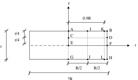
BEM solution (Boundary conditions (BC’s) are also specified)... 115 Figure 5.2 Definition of the sections in the bonded elastic disc over which the
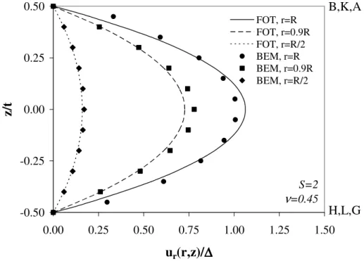
displacement and stress distributions are plotted ... 116 Figure 5.3 Variation of normalized radial displacement through the layer
thickness at various sections... 117 Figure 5.4 Variation of normalized radial displacement through the radius at
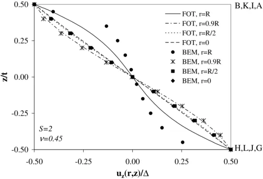
z=0, t/4... 117 Figure 5.5 Variation of normalized axial displacement through the layer
thickness at various sections... 118 Figure 5.6 Variation of normalized axial displacement through the radius at
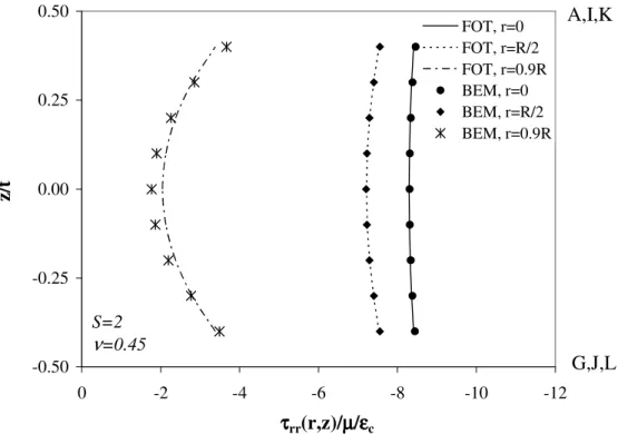
z=t/4... 118 Figure 5.7 Variation of normalized radial stress through the layer thickness... 120 Figure 5.8 Variation of normalized axial stress through the layer thickness ... 120 Figure 5.9 Variation of normalized radial, circumferential and axial stresses
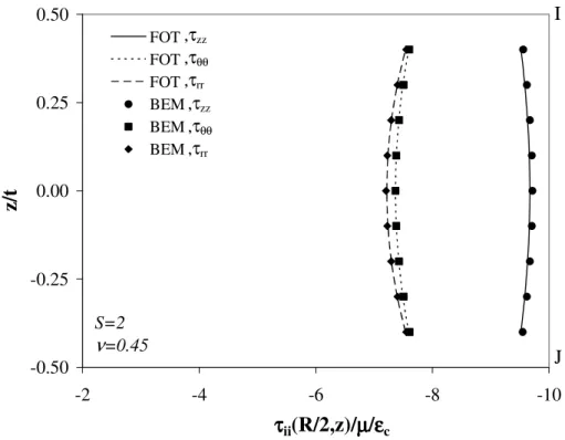
(τii/µεc for i=r,θ,z) through the layer thickness at r=R/2 ... 121
Figure 5.10Variation of normalized shear stress through the layer thickness ... 121 Figure 5.11Variation of normalized axial stress through the radius ... 122 Figure 5.12 Variation of normalized radial, circumferential and axial stresses
(τii/µεc for i=r,θ,z) through radius at z=t/4 ... 122
Figure 5.13Variation of normalized shear stress through the radius ... 123 Figure 5.14 Effect of mesh size on BEM predictions for stress distributions... 125 Figure 5.15 Discretization of the HC-shaped bonded elastic layer for BEM
Figure 5.16 Variation of shear stress through the layer thickness in the HC-shaped layer (S0=2, ν=0.499) with different radius ratios predicted by
FOT (continuous lines) and BEM (discrete points) ... 128 Figure 5.17 Normal stress distributions through the layer thickness in the
HC-shaped layer (S0=2, ν=0.499) with different radius ratios predicted by
FOT (continuous lines) and BEM (discrete points) ... 129 Figure 5.18 Stress distributions over the bonded faces in the HC-shaped layer
(S0=2, ν=0.499) with different radius ratios predicted by
FOT (continuous lines) and BEM (discrete points) ... 130 Figure 5.19 Discretization of the IS-shaped bonded elastic layer for the
compression problem (Boundary conditions (BC’s) are also specified)... 131 Figure 5.20 Assessment of the validity of two basic assumptions through the
comparison of FOT (continuous lines) and BEM (discrete points) predictions134 Figure 5.21 Discretization of the IS-shaped bonded elastic layer for the bending
problem (Boundary conditions (BC’s) are also specified) ... 135 Figure 5.22 Displacement distributions through the layer thickness under pure
bending ... 136 Figure 5.23 Stress distributions through the layer thickness under pure bending . 136 Figure 5.24 Stress distributions at the bonded faces under pure bending... 137 Figure 5.25 Discretization of the IS-shaped bonded elastic layer for apparent
shear problem (Boundary conditions (BC’s) are also specified)... 138 Figure 5.26 Displacement distributions under apparent shear ... 138 Figure 5.27 Stress distributions at the bonded faces under apparent shear... 139 Figure 6.1 Effect of shape factor and Poisson’s ratio on compression modulus ... 141 Figure 6.2 Effect of Poisson’s ratio on displacement distributions in lateral
direction under uniform compression... 142 Figure 6.3 Effect of Poisson’s ratio on displacement distributions through the
layer thickness under uniform compression ... 143 Figure 6.4 Effect of shape factor and Poisson’s ratio on maximum bulging under
Figure 6.5 Effect of shape factor and Poisson’s ratio on axial displacement of the layer at the quarter thickness under uniform compression ... 145 Figure 6.6 Effect of Poisson’s ratio on stress distributions in lateral direction in
bonded IS-shaped layers with S=1 (left hand side) and S=30 (right hand side)146 Figure 6.7 Effect of shape factor on stress distributions in lateral direction in
bonded IS-shaped layers for ν=0.45 (left hand side), ν=0.499 (right hand side) ... 147 Figure 6.8 Effect of Poisson’s ratio on stress distributions in axial direction in
bonded IS-shaped layers with S=1 (left hand side) and S=30 (right hand side)150 Figure 6.9 Effect of shape factor on stress distributions in axial direction in
bonded IS-shaped layers for ν=0.45 (left hand side), ν=0.499 (right hand side) ... 151 Figure 6.10 Comparison of the predictions of FOT (continuous lines) and PM
(discrete points) for lateral normal stress distribution in the axial direction.... 152 Figure 6.11 Effect of shape factor and Poisson’s ratio on maximum normalized
stresses under uniform compression... 155 Figure 6.12 Predictions of zeroth and first order theories for bending modulus ... 156 Figure 6.13 Effect of Poisson’s ratio and shape factor on Ec/Eb ratio ... 157 Figure 6.14 Effects of shape factor and Poisson’s ratio on displacement
distributions under pure bending ... 158 Figure 6.15 Effect of Poisson’s ratio on stress distributions in lateral direction in
bonded IS-shaped layers with S=2.5 (left hand side) and S=30 (right hand side) ... 160 Figure 6.16 Effect of Poisson’s ratio on stress distributions in axial direction in
bonded IS-shaped layers with S=2.5 (left hand side) and S=30 (right hand side) ... 162 Figure 6.17 Effect of shape factor on stress distributions in axial direction in
bonded IS-shaped layers for ν=0.45 (left hand side), ν=0.499 (right hand side) ... 163
Figure 6.18 Effect of shape factor and Poisson’s ratio on magnitude and location of maximum lateral normal stress under pure bending ... 164 Figure 6.19 Maximum pressure in a bonded elastic layer under pure bending ... 166 Figure 6.20 Assessment of the predictions of the pressure method (PM) for the
“critical” pressure in an IS-shaped layer under pure bending ... 167 Figure 6.21 Effect of shape factor and Poisson’s ratio on maximum shear stress
under pure bending ... 168 Figure 6.22 Effect of shape factor and Poisson’s ratio on apparent shear modulus169 Figure 6.23 Comparison of the prediction of FOT for apparent shear modulus of
an IS-shaped layer with the predictions of the other expressions in literature. 170 Figure 6.24 Displacement distributions in axial direction under apparent shear ... 171 Figure 6.25 Axial and shear stress distribution in lateral direction under apparent
shear... 172 Figure 7.1 Effect of radius ratio on Ec,HC, normalized with respect to (a) µ and
(b) Ec,C, for two different initial shape factors So=2,30... 175
Figure 7.2 Effect of Poisson’s ratio and initial shape factor on Ec,HC, normalized
with respect to Ec,C, for two different initial shape factors... 178
Figure 7.3 Ec predictions computed from (solid) C, exact HC, “equivalent” C
and “equivalent” IS expressions for So=2 (left hand side) and So=30 (right
hand side)... 180 Figure 7.4 Assessment of the success of the “equivalent” C (left hand side) and
“equivalent” IS (right hand side) expressions in predicting Ec,HC... 182
Figure 7.5 Effect of radius ratio on axial stress distribution in radial direction in bonded annular layers with So=2 (left hand side) and So=30 (right hand side) 184
Figure 7.6 Comparison of the predictions of the exact HC expression and the “equivalent” IS expression for axial stress distribution in radial direction in an HC-shaped layer with β=0.5 for two different initial shape factors ... 187 Figure 7.7 Effect of initial shape factor on shear stress distribution in radial
direction in a bonded annular layer of slightly compressible material (ν=0.499) ... 189
Figure 7.8 Effect of radius ratio on radial stress distribution in axial direction in bonded annular layers with So=2 (left hand side) and So=30 (right hand side) 190
Figure 7.9 Effect of shape factor and Poisson’s ratio on maximum shear stress in C-shaped bonded elastic layers ... 191 Figure 7.10 Variation of shear stress at the inner (left hand side) and outer (right
hand side) faces of a bonded annular layer with initial shape factor... 193 Figure 7.11 Magnification of maximum shear strain due to the existence of a
hole in the center of a bonded circular disc as a function of radius ratio ... 195 Figure 7.12 Assessment of the success of the simple expression proposed by
Constantinou et al. [16] for the maximum shear strain ratio (discrete points in filled triangular shapes) ... 197 Figure 8.1 Effect of reinforcement flexibility on normalized compression
modulus of bonded IS-shaped layers... 199 Figure 8.2 Effects of shape factor and Poisson’s ratio on normalized
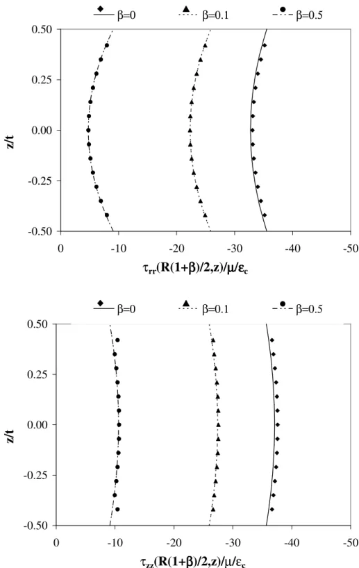
compression modulus of an IS-shaped layer bonded to flexible reinforcements ... 201 Figure 8.3 Effect of reinforcement flexibility on stress distributions in lateral
direction under uniform compression for S=1... 202 Figure 8.4 Effect of reinforcement flexibility on normal stress distributions in
lateral direction under uniform compression for S=30... 204 Figure 8.5 Effect of reinforcement flexibility on shear stress distribution in
lateral direction under uniform compression for S=30... 205 Figure 8.6 Effect of reinforcement flexibility on normal stress distributions in
axial direction under uniform compression for S=1... 205 Figure 8.7 Effect of reinforcement flexibility on normal stress distributions in
axial direction under uniform compression for S=30... 206 Figure 8.8 Effect of reinforcement flexibility on maximum stresses in a bonded
IS-shaped layer under uniform compression... 208 Figure 8.9 Effect of shape factor on maximum stresses in an IS-shaped layer
Figure 8.10 Predictions of zeroth and first order theories for bending modulus of IS-shaped layers bonded to flexible reinforcements ... 211 Figure 8.11 Effect of reinforcement flexibility on Ec/Eb ratio ... 212 Figure 8.12 Effect of reinforcement flexibility on normalized bending modulus . 213 Figure 8.13 Effect of reinforcement flexibility on stress distributions in lateral
direction under pure bending for S=2.5... 214 Figure 8.14 Effect of reinforcement flexibility on normal stress distributions in
lateral direction under pure bending for S=30... 216 Figure 8.15 Effect of reinforcement flexibility on shear stress distribution under
pure bending in lateral direction for S=30... 217 Figure 8.16 Effect of reinforcement flexibility on lateral normal stress
distribution in axial direction under pure bending for S=2.5 (on the left hand side) and S=30 (on the right hand side)... 217 Figure 8.17 Effect of reinforcement flexibility on maximum shear stress in an
IS-shaped layer bonded to extensible reinforcements under pure bending... 219 Figure 8.18 Predictions of zeroth and first order theories for warping constant
“f” ... 220 Figure 8.19 Effect of reinforcement flexibility on warping constant “f”... 222 Figure 8.20 Predictions of zeroth and first order theories for warping modulus ... 222 Figure 8.21 Effect of reinforcement flexibility on normalized warping modulus . 223 Figure 8.22 Effect of reinforcement flexibility on Ec/Ew ratio... 225 Figure 8.23 Effect of reinforcement flexibility on stress distributions in lateral
direction under pure warping for S=2.5 ... 226 Figure 8.24 Effect of reinforcement flexibility on lateral normal stress
distribution in lateral direction under pure warping for S=30... 227 Figure 8.25 Effect of reinforcement flexibility on shear stress distribution under
pure bending in lateral direction for S=30... 228 Figure 8.26 Convergence of FOT solution to PM solution for stress distributions
Figure 8.27 Convergence of FOT solution to the “short beam” solution for axial stress distribution in an LSF (S=2.5) and HSF (S=30) layer of compressible (ν=0.3) materials bonded to flexible reinforcements (kf/µt=30000) ... 230
Figure 8.28 Effect of reinforcement flexibility on stress distributions in axial direction under pure warping for S=2.5 ... 232 Figure 8.29 Effect of reinforcement flexibility on stress distributions in axial
CHAPTER 1
INTRODUCTION
1.1 BONDED ELASTIC LAYERS
Elastic layers bonded to reinforcing sheets have long been used as suspension and support systems, compression and shear mountings, and as sealing components [1]. Earlier studies on “bonded elastic layers” [2,3] have shown that the reinforcing plates bonded to top and bottom faces of an elastic layer may cause considerable changes on the layer behavior. These studies have also shown that the effects of the bonded surfaces on the layer behavior highly depend on the geometric and material properties of the layer, and become much more pronounced as material compressibility decreases, i.e., as Poisson’s ratio approaches 0.5, since, as stated by Lindley [4], “for materials such as rubber which have a low shear modulus but a relatively high bulk modulus, any restrictions on their freedom to change shape can have a very marked effect on their stiffness in compression”.
It is now very well known that not only the compression but also the bending stiffness of a bonded rubber layer may be several orders of magnitude greater than that of the corresponding unbonded layer. It is to be noted that despite their significant effects on the compressive or bending behavior, the bonded surfaces do not influence the shear behavior of the layer considerably. This is an important property considering that the resistance of a soft elastic layer to compression and bending can be increased without compromising from its flexibility in shear.
Composed of several elastomer layers sandwiched between and bonded to steel plates, “elastomeric bearings” have been developed using this favorable mechanical property of bonded elastic layers. In the earlier applications, elastomeric bearings were primarily used as expansion bearings for highway bridges to accommodate thermal expansion and slow differential movements, helicopter rotor bearings, wharf fenders, elastic foundations to machinery and motors and as sealing components. Recently, their applications have been extended to seismic isolation, which is a new earthquake resistant design concept in which flexible and energy dissipating elements are inserted at the base of the structure to reduce the transmission of seismic force from the soil to the structure. The main philosophy behind this technique is to shift the fundamental period of the structure sufficiently away from both its fixed-base period and the predominant period of most earthquakes so that the behavior of the entire structure can be governed by its first mode where the deformations are concentrated at the isolation level, while the superstructure moves almost rigidly.
Combination of soft elastomer layers, which provide flexibility in horizontal direction to shift the period of the isolated structure away from its fixed-base period, with comparatively rigid steel plates, which provide resistance to support the heavy weight of the superstructure and to resist possible rotations, in a single unit makes multi-layered steel-laminated elastomeric bearings (Figure 1.1) favorable to use as effective seismic isolators [5-7].
Under the applied loads, the behavior of a steel-laminated elastomeric bearing is controlled primarily by the elastomer thickness. Independent from the interior steel-elastomer composition, the total elastomer thickness is the main parameter determining the shear stiffness of the bearing. On the other hand, the thickness of the individual “bonded elastomer layers” governs the behavior of the bearing under compression and bending. In fact, as shown by many analytical and experimental studies, it is the aspect ratio of a typical interior bonded elastomer layer (Figure 1.2), named as shape factor (S), which mainly controls the compressive and bending behavior of a multi-layered elastomeric bearing.
Figure 1.1 A typical steel-reinforced elastomeric bearing used in seismic isolation technique (taken from [8])
Figure 1.2 Definition of shape factor for a cylindrical steel-reinforced elastomeric bearing (taken from[9])
Shape factor of a bonded elastic layer is defined as the ratio of “one loaded area” to the “entire force free area”, i.e., the area of the perimeter free to bulge, as illustrated in Figure 1.2 [9]. Accordingly, “thin” layers which have high shape factors, called HSF (high shape factor) layers, have considerably high compressive and bending stiffnesses while “thick” layers which have low shape factors, called LSF (low shape factor) layers, have low stiffnesses. As it can easily be inferred, an HSF bearing is mainly designed to provide isolation only in the horizontal direction while an LSF bearing can provide three dimensional (3D) isolation.
While most of the elastomeric bearings used in seismic isolation technique are reinforced with steel plates, in a recent study, Kelly [10] proposed to replace steel reinforcement with fiber reinforcement to produce cost-effective light-weight isolators to be used in developing countries. Since with recent technology, the fiber materials with elastic stiffness comparable to that of steel can be produced, it is possible to produce a fiber-reinforced bearing which matches the behavior of the steel-reinforced bearing [11]. Even though the idea of using fiber reinforcement in seismic isolation bearings is very new, the viability of the concept has already been shown through several experimental studies [12-15].
Although the use of bonded elastic layers for reducing the devastating effects of severe earthquakes on structures is relatively new, its use in engineering applications is not new, as already mentioned. In fact, the studies on bonded rubber layers, or more generally on bonded elastic layers, go back as early as the beginning of the twentieth century. Even though the behavior of most elastomers can be highly nonlinear and they may undergo considerable finite deformations, in most of these analytical treatments, linear behavior is assumed and the derivations are performed for small strains because the use of finite strain analysis with nonlinear constitutive models usually leads to highly nonlinear and complex equations [7]. Further, with the purpose of obtaining simple design formulas, some simplifying assumptions are used in these studies, such as parabolic bulging assumption for the lateral boundary of the layer, the assumption that horizontal plane sections remain plane during deformation, rigidity assumption for the reinforcing sheets, “pressure” assumption for the state of stress, incompressibility assumption for the layer material, etc. [16].
It can also be recognized that most of the earlier studies on bonded elastic layers have focused on the derivation of closed form expressions only for the stiffnesses, particularly the compressive stiffness, of the layers. On the other hand, as emphasized by Gent et al. [17], the knowledge of the detailed displacement and stress distributions, and the location and magnitude of the critical local stresses developing in the layer is also essential for a rational design. For instance, an important parameter that can control the design of a bonded elastic layer is the bulging of the layers. Control of bulging is essential because increased bulging implies increased shear strain [18]. Similarly, the interfacial stresses, i.e., the stresses developing at the bonded faces, become one of the main parameters for the design of the reinforcements. Reinforcing sheets can fail due to excessive shear or normal stresses. Likewise, the knowledge of stress distribution at reinforcement-rubber bond is essential for the bond design. In some cases, even the failure of the elastomer itself may be taken as a design criterion, which can be evaluated only if the detailed stress distributions are known [17].
Thus, in order to study the behavior of a bonded elastic layer thoroughly, it is necessary to investigate not only the stiffness of the layer but also the displacement and stress distributions developing in the layer in detail. However, as already discussed, most of the earlier studies on bonded elastic layers have been based on assumed displacement fields with assumed stress distributions, which usually lead to approximate and/or ‘‘average’’ solutions, hindering a comprehensive study on displacement and stress distributions over the entire layer and on the effects of the geometrical and material properties on the layer behavior.
1.2 AIM OF THE DISSERTATION The main object of this dissertation is
(i) to develop a new formulation for linear analysis of bonded elastic layers by removing most of the in-priori assumptions used in the earlier formulations, and
(ii) to study comprehensively, by using the advanced solutions obtained from this new formulation, the behavior of bonded elastic layers under their fundamental deformation modes.
The new analytical formulation presented in this dissertation is developed by employing an approximate theory proposed by Mengi [19], which is based on a modified version of the Galerkin Method. The use of the theory by Mengi [19] in the formulation brings in the following distinct advantages over the other formulations in literature:
• Since the displacement boundary conditions are included in the formulation itself, any possible inconsistency between the assumed displacement field and the boundary conditions at the bonded surfaces are eliminated. Thus, there is no need to start the formulation with some assumptions on stress and/or displacement distributions, or some limitations on the geometrical and material properties.
• Since the effect of compressibility is naturally included in the formulation, the solutions are valid not only for incompressible or nearly incompressible materials but also for highly compressible materials.
• Because of the appearance of face variables in the approximate theory, there is no need to make additional assumptions when the flexibility of the reinforcement is included in the formulation.
• The order of the theory is arbitrary; this facilitates improving the prediction of the theory and obtaining solutions much closer to the exact by increasing its order.
Consequently, within the framework of this new formulation, it is possible to derive the solutions in a form which can be used for the comprehensive study of stress and displacement distributions at any section in a bonded elastic layer.
While studying the behavior of bonded elastic layers in their basic deformation states, the main emphases are given to the investigation of the effects of three key parameters
• shape factor of the layer
• Poisson’s ratio of the layer material • flexibility of the reinforcing sheets on
• effective moduli of the layer
• displacement and stress distributions over any section in the layer • location and magnitude of maximum stresses developing in the layer.
The effects of the existence of a central hole on compressive behavior of bonded elastic discs are also examined in the dissertation.
1.3 SCOPE AND ORGANIZATION OF THE DISSERTATION
The dissertation starts with a review chapter where the theory and the earlier studies on bonded elastic layers are discussed (CHAPTER 2). Then, in CHAPTER 3, the new formulation proposed in this dissertation for the analysis of bonded elastic layers is presented. Since in the dissertation, the main emphasis is given to the elastic layers bonded to rigid reinforcements, first, the rigidly-bonded case is discussed in this chapter for three fundamental deformation modes: (i) uniform compression, (ii) pure bending and (iii) apparent shear. For each deformation mode, keeping the order of the theory arbitrary, the relevant equations are presented in general forms, in view of displacement boundary conditions at the top and bottom faces of the layer. To have a formulation applicable to all possible shapes (circular as well as infinite-strip, square and rectangular shapes), the reduced governing equations, originally derived in rectangular Cartesian coordinates, are also extended to cylindrical coordinates. The constants which appear in the approximate theory are determined and tabulated by choosing the distribution functions employed in the theory as Legendre polynomials. Regardless of the layer shape or order of the theory, determination of displacement/stress distributions and relevant effective modulus for each deformation mode is also formulated and presented. Then, in the same chapter (CHAPTER 3), the formulation is extended to the case where the elastic layer is bonded to extensible reinforcements. This case is discussed for three
simple deformation modes: (i) uniform compression, (ii) pure bending and (iii) pure warping. Similar to the rigid-reinforcement case, for each deformation mode, reduced governing equations are derived by keeping the shape of the layer and order of the theory arbitrary. However, in this case, the relevant equations are presented only in rectangular Cartesian coordinates.
CHAPTER 4 contains the application of the general formulation for various shapes of bonded elastic layers. In this chapter, closed form solutions for displacement/stress distributions and effective layer moduli are obtained, through the solution of governing equations presented in CHAPTER 3, for the cases involving an elastic layer of
• infinite-strip shape, bonded to rigid reinforcements
• solid and hollow circular shape, bonded to rigid reinforcements • infinite-strip shape, bonded to extensible reinforcements.
CHAPTER 5 is devoted to the assessment of the new formulation proposed in the dissertation, which involves comparing the analytical solutions derived using first order theory for elastic layers of infinite-strip, circular and hollow-circular shapes, bonded to rigid reinforcements with the numerical solutions. For this purpose, some simple ‘numerical’ problems are designed and analyzed using a widely used numerical technique: boundary element method (BEM).
The solutions obtained in CHAPTER 4 are used
• in CHAPTER 6, to investigate the effects of shape factor and Poisson’s ratio on the behavior of infinite-strip elastic layers bonded to rigid surfaces
• in CHAPTER 7, to study the effect of the presence of a central hole on the compressive behavior of elastic discs bonded to rigid reinforcements
• in CHAPTER 8, to investigate the effect of reinforcement flexibility on the behavior of bonded infinite-strip elastic layers.
Finally, in view of the findings of the dissertation, some conclusions are stated in CHAPTER 9.
CHAPTER 2
THEORY ON BONDED ELASTIC LAYERS
2.1 ELASTIC LAYERS BONDED TO RIGID SURFACES
As stated by Gent and Meinecke [20], there are three basic deformation modes for an elastic layer bonded to rigid surfaces (Figure 2.1a): (i) uniform compression/extension (Figure 2.1b), (ii) pure bending (Figure 2.1c) and (iii) apparent shear (Figure 2.1d). Comprehensive analysis of a bonded elastic layer under each fundamental deformation mode is essential for understanding the effects of the bonded surfaces.
As already mentioned, in the last century, many researchers have studied the behavior of bonded elastic layers, specifically bonded rubber layers. Most of these studies have been conducted to determine the compression stiffness of the rigidly-bonded rubber layers. According to Kelly [7], “the first analysis of the compression stiffness was done using an energy approach by Rocard” in 1937 “and further developments were made” by Gent and Lindley [2] and Gent and Meinecke [20]”. These earliest studies put forward three basic assumptions for small deformation and linear analysis of bonded elastic layers:
(i) horizontal plane sections remain plane after deformation,
(ii) initially vertical lateral surfaces take a parabolic shape in the deformed configuration (parabolic bulging assumption),
(iii) state of stress at any point in the material is dominated by the hydrostatic pressure (“pressure” assumption).
a. undeformed shape b. deformed shape under uniform compression
c. deformed shape under pure bending
d. deformed shape under apparent shear
Figure 2.1 An elastic layer bonded to rigid surfaces under its three basic deformation modes
These three assumptions can be accepted as the fundamental assumptions of the linear theory developed for the analysis of bonded elastic layers since most of the earlier studies on this subject have been conducted based on these three assumptions. As it will be discussed later in detail, even if different formulations are used, these fundamental assumptions always lead to the same differential equation in terms of the “pressure” term, which is commonly called as the “pressure equation”. Most of the case, the solution of this differential equation was sufficient for the analysis since the effective stiffness of the layer can easily be derived once the pressure distribution is obtained. Thus, it seems to be reasonable to name all the formulations developed based on these three fundamental assumptions as the “pressure method”. Since most of the studies in literature have been based on this method of analysis, in the following sections, first, the pressure method is reviewed.
h=t/2 z x h=t/2 δ/2 z x δ/2 M F F M z x P P ∆/2 ∆/2 z x φ/2 φ/2 M M
In this review, only the formulations of Gent and Lindley [2] and Kelly [7] are discussed with some detail. For the other formulations, the related references should be referred. After defining these two methodologies, the closed form expressions derived using different formulations are presented without giving details on their derivations. Other studies including those that used energy methods, variational methods and finite or boundary element methods are also mentioned shortly.
Considering that several different notations have been defined and used in the previous studies for the geometrical properties of the elastic layer and/or for the coordinate system to which the derived equations are referred, it seems to be reasonable and practical to define the notation that is used throughout this chapter at this point. Table 2.1 summarizes the geometrical properties of the commonly used cross sectional shapes for bonded elastic layers, namely, infinite strip (IS), hollow circular (HC) and rectangular (RC) shapes. It should be noted that circular (C) section is a special case of HC section in which a=0. Similarly, square (SQ) section is a special case of RC section in which b=a.
In linear elasticity, the state of an isotropic material in its undeformed configuration can be described by two basic elastic constants [21]: bulk modulus K, which is used to define the resistance of the material to hydrostatic pressure, and shear modulus µ, which is used to define the resistance of the material to simple shearing forces. The other elastic constants; namely, Young’s modulus E, Poisson’s ratio ν, and Lamé constant λ can easily be derived from these constants using the simple relations given below:
9 3 K E K µ µ = + , 1 3 2 2 3 K K µ ν µ − = + and 3 2 3 K µ λ= − (2.1)
The selection of the two basic elastic constants to be used in the equations is usually related to the formulation. The presentation of the fundamental equations or the resulting expressions may be much easier when the suitable “pair” of material constants is used. Since the conversions between these elastic constants can easily be made using Eqs. (2.1), in the following sections, the form of the equations is not changed and the researchers’ preference for the two elastic constants is accepted.
Table 2.1 Definition of the notation for bonded layers of different shapes (Figure for the rectangular shape is taken from [22])
Shape Geometrical Properties Factor Shape
Infinite Strip (IS) width 2w w t Hollow Circular (HC) outer radius R, inner radius a 2 R a t − Rectangular (RC) sides 2a,2b ( ) ab t a b+ t/2 z x t/2 w w 2R t/2 z r t/2 2a
2.1.1 Compressive Behavior
The vertical stiffness (Kv) of a bearing composed of several bonded rubber layers (without any horizontal displacement) is given by the following well-known expression [6]: c v r E A K t = (2.2)
where A is the cross sectional area of the reinforcing plates, tr is the total rubber thickness and Ec is named as the “effective compression modulus” of the bearing. Effective (or sometimes called apparent) compression modulus of a multilayered steel laminated elastomeric bearing can be determined from the effective compression modulus of its typical interior rubber layer bonded to steel plates, which is simply the ratio of the nominal compressive stress (σc) to the nominal compressive strain (εc) as follows:
c c c E σ ε = (2.3) in which c P A σ = and c t ε = ∆ (2.4)
where P is the applied compressive load, ∆ is the corresponding vertical displacement and t is the thickness of the typical interior rubber layer, as shown in Figure 2.1a,b.
As discussed in detail by Lindley [4], there are three limiting cases for the compression of an elastic layer.
i. Compression without any restraint: if a layer is free from any lateral restraint (S→0), it will be in “homogeneous compression” state under a uniaxial load. Compression modulus in this case, denoted as (Ec)0, can be written in terms of
elastic modulus E and Poisson’s ratio ν as [23,24]:
( )
02
for symmetrical cross sections for plane strain case
1 c E E E ν = − (2.5)
ii. Compression with complete lateral restraint: This case corresponds to the compression of an infinite strip layer whose bulging at the lateral faces is completely restrained (S→∞). Compression modulus in this case, denoted as (Ec)∞, can be expressed in terms of E and ν as:
( )
2 (1 ) (1 2 ) c E ν E ν ν ∞ − = − − (2.6)iii. Bulk compression: Under equal hydrostatic pressure in all three directions, the behavior of the layer is governed by the bulk modulus K, which is related to (Ec)∞ with
( )
(1 ) 3(1 ) c K ν E ν ∞ + = − (2.7)From Eq. (2.7), it is clear that (Ec)∞≥K for all materials (equality holds only for incompressible materials). Thus, it can be concluded that the compression modulus of a bonded elastic layer (Ec) is always greater than (Ec)0, which requires
perfect slip, but smaller than (Ec)∞, which requires infinite lateral restraint. While LSF layers are closer to the lower bound (Ec)0, as shape factor increases, Ec
approaches to the upper bound (Ec)∞. This range is very sensitive to the Poisson’s ratio of the material and can increase considerably as ν→0.5. Thus, as stated in [4], “for materials such as rubber which have a low shear modulus but a relatively high bulk modulus, any restrictions on their freedom to change shape can have a very marked effect on their stiffness in compression”.
This effect of bonding the on compressive behavior of rubber layers was investigated by Gent and Lindley [2] through an experimental study in which the behavior of various bonded rubber blocks with different geometries was examined under uniform compression. The tested blocks had one of the following four shapes: C, HC with R/a ratios of 8, 4 or 2, SQ or RC with a/b ratio of 3. The discrete points, in the shapes of circles, squares and rectangles, plotted in the graphs presented in Figure 2.2a-b show the experimental data obtained by the researhers for the compression modulus of the tested blocks [2].
Figure 2.2 Compression modulus of bonded rubber blocks (taken from [2])
It should be noted the points plotted in the shapes of squares and circles in Figure 2.2a correspond to the experimental data, respectively, for SQ and C-shaped rubber blocks. Similarly, the points plotted in the shapes of rectangles and circles in Figure 2.2b correspond to the data obtained from the tests of RC and HC-shaped blocks. The test results for the HC-shaped blocks with different R/a ratios are differentiated by plotting the data for the blocks with a R/a ratio of 8 in the shape of “empty” circles and those with R/a ratios of 4 or 2 in the shape of “filled” circles. The graphs in Figure 2.2 clearly illustrate the strong effect of the shape factor of a bonded elastic layer on its compression modulus: the compression modulus of an HSF layer can be about 500 times greater than that of an LSF layer.
It is to be noted that the continuous and dashed curves tried to fit to the test data in Figure 2.2a,b were drawn, by the researchers, using the approximate relations they derived for the compression modulus of IS and C-shaped bonded elastic layers. In their theoretical study, Gent and Lindley [2] considered that, under
C om p re ss io n M od u lu s (k g/ cm ) ( lo g sc al e)
Shape Factor (log scale) Shape Factor (log scale)
(a) (b)
Exp, C-shape Exp, SQ-shape Anal, Eq. (2.12)2 Anal, Eq. (2.13)
Exp, HC-shape with R/a=8 Exp, RC-shape with b/a=3 Anal, Eq. (2.12)1
Anal, Eq. (2.13)
uniform comprssion, the total displacement of a bonded rubber layer is composed of the superposition of two simple displacements; (1) pure homogeneous compression of the corresponding unbonded layer and (2) the additional displacement required to keep the points on the bonded surfaces in their original positions. Under homogenous compression, the deformation of the layer is uniform. Thus, for incompressible case, the compressive stress developing in IS and C-shaped bonded layers under the 1st stage deformations, (σz1i,IS and σz1i,C) are
1 , 4 3 GL z i IS c E σ = − ε and 1 , GL z i C E c σ = − ε (2.8)
Note that as in Eq. (2.8), a superscript consisting of the initial letters of the researchers’ surnames (e.g., GL in this case) will be added to any formula/equation that will be given in this review for reader’s convenience.
The formulation of the second stage deformations requires some simplifying assumptions on the displacement and stress distributions in the layer. Using the fundamental assumptions of the pressure method and assuming strict incompressibility (ν=0.5), Gent and Lindley [2] derived the following well-known pressure equation, 2 2 12 c p t µ ε ∇ = − (2.9) where 2 2 2 2 2 ( , ) p p p x y x y ∂ ∂ ∇ = + ∂ ∂ or 2 2 2 1 ( ) d p dp p r dr r dr ∇ = + (2.10)
in Cartesian coordinates or cylindrical coordinates, respectively. It is to be noted that their formulation was rather complicated. They derived the incompressibility equation from the geometry of an IS-shaped layer by equating the volumes contained between the central vertical plane and a plane at a distance x from the center in the deformed and undeformed states as shown in Figure 2.3. Similarly, they derived the equilibrium equation in the horizontal direction by computing the excess hydrostatic pressure (dpx) that is required to maintain the parabolic bulging
Figure 2.3 Deformed and undeformed configurations for an IS-shaped bonded elastic layer under uniform compression (taken from [20])
Using the “pressure free boundary conditions” at the lateral surfaces, Gent and Lindley [2] solved Eq. (2.9) and obtained the following expressions for the pressure distribution in IS and C-shaped bonded layers (σz2i,IS and σz2i,C):
, 2 2 2 , ci IS 2 1 2 GL GL z i IS c x p E S w σ = − = − ε − , 2 2 2 , , 4 1 2 GL GL z i C ci C c r p E S R σ = − = − ε − (2.11)
It should be noted that before deriving the expressions for the compression modulus, it is necessary to superpose the first and second stage solutions; i.e., add Eqs. (2.8) and Eqs. (2.11).
Thus, the Gent and Lindley’s formulation leads to the following well-known expressions for the compression modulus of IS and C-shaped incompressible bonded layers (Eci IS, and Eci C, ):
(
2)
, 4 1 3 GL ci IS E = E +S and(
2)
, 1 2 GL ci C E =E + S (2.12)It is worth mentioning that, realizing the significant effect of the material compressibility in HSF rubber layers, Gent and Lindley [2] also proposed an “ad-hoc” modification -independent of the shape of the layer- to account for the bulk compressibility of rubber on compression modulus.
1 1 1
GL GL cc ci
E = E +K (2.13)
where Ecc is the compression modulus including material compressibility and Eci is
the validity of their analytical formulation, the researchers compared the predictions of their analytical solutions with the experimental results (Figure 2.2). It is to be noted that the continuous curve in Figure 2.2a is plotted using the second of Eqs. (2.12). Similarly, the continuous curve in Figure 2.2b is plotted using the first of Eqs. (2.12). Since these “incompressible” curves deviate from the experimental data considerably especially when S is large, the researchers also plot the “compressible” curves, in dashed lines, using Eq. (2.13). By comparing their analytical predictions with the test data, Gent and Lindley [2] suggested that the Ec expression derived for
C-shaped layers (the second of Eqs. (2.12)) can be used for layers with compact sections; i.e., nearly square or circular cross section with a small hole, while the use of the Ec expression derived for IS-shaped layers (the first of Eqs. (2.12)) is more
convenient for layers with very dissimilar side lengths or large holes.
Recognizing the similarity of the pressure equation to the equation of torsion problem for torsional stress function, Gent and Meinecke [20] solved the pressure equation for different shapes by adopting the problem to its corresponding torsion problem. The following expression for “incompressible” compression modulus for
RC-shaped layers (Eci,RC) is worth mentioning in this review:
2 2 , 2 2 2 2 5 5 1,3,5 4 2 4 192 1 (1 tanh( )) 3 3 2 3 2 GM ci RC n ab t a a n b E E a b t t b n a π π = + = − + − + +
∑
(2.14)which leads to the following simple expression for the special SQ case (Eci,SQ):
2 , 1 0.562 2 GM ci SQ a E E t ≅ + (2.15)
It is to be noted that the expression in the first parenthesis in Eq. (2.14), which represents the contribution of the first stage solution, is an empirical relation suggested in [20] in such a way that it satisfies the two basic requirements: it yields 1.0 for symmetrical shapes and 4/3 for plane strain case.
For the prediction of the pressure method for the compression modulus of incompressible HC-shaped layers, it is necessary to refer to the more recent studies. The expression derived by Gent [24] for the compression modulus of
(
)
(
)
2 2 2 2 , 2 1 1 2 ( / ) G ci HC R a E E R a t In R a − = + + − (2.16)Although the incompressibility assumption is generally accepted as a realistic assumption for LSF rubber layers, the contribution of bulk compression of rubber to the total compression of the layer has to be considered for HSF rubber layers [25]. Lindley [26] may be accepted as the first researcher attempting to derive closed form expressions for the “compressible” compression modulus of bonded elastic layers. In his analytical treatment, which was based on an energy approach, in addition to the three fundamental assumptions of the pressure method, he assumed that the distribution of bulk strain over any horizontal section is parabolic. He obtained closed-form expressions for the compressible compression modulus of IS and C-shaped layers.
Compared to the above-mentioned formulations of the pressure method, Kelly’s formulation [7] can be said to be much simpler and more methodological. He started his formulation by simplifying the displacement field of the rubber layer based on the displacement assumptions of the pressure method. Thus, for a bonded elastic layer with an arbitrary shape, Kelly [7] wrote the displacements in the x, y
and z directions, denoted as u, v and w respectively, in the form of: 2 2 4 ( , , ) o( , )(1 z ) u x y z u x y t = − 2 2 4 ( , , ) o( , )(1 z ) v x y z v x y t = − ( , , ) ( ) w x y z =w z (2.17)
where u0 and v0 are the maximum bulging of the layer in x and y directions,
respectively. From Eq. (2.17), it is easy to see that the displacement function in z
direction represents directly the first kinematics assumption, i.e., the assumption that the horizontal planes remain horizontal, while the first two functions written for the horizontal components are based on the second kinematics assumption, i.e., the parabolic bulging.
In the case of strict incompressibility, the incompressibility equation, i.e.,
0 xx yy zz
ε +ε +ε = when written in terms of the normal strain components (εxx,εyy,εzz), can be written, in terms of the displacement functions, as:
(
0, 0,)
22 , 4 1 0 x y z z u v w t + − + = (2.18)where the commas imply partial differentiation with respect to the indicated coordinate. If the effect of compressibility is wanted to be included, the equation of incompressibility must be replaced with εxx+εyy +εzz = −p K/ , where K is the bulk modulus of the material, which leads to
(
0, 0,)
22 , 4 1 x y z z p u v w t K + − + = − (2.19)Assuming infinitesimal strains and linearly elastic material behavior, integrating Eq. (2.18) or Eq. (2.19) through the layer thickness, writing equilibrium equations in x
and y directions and using the stress assumption of the pressure method (i.e., that
xx yy zz p
σ =σ =σ = − where σxx,σyy,σzz are normal stress components), the following equations are obtained for the pressure term p(x,y)
2 2 12 c p t µ ε ∇ = − (2.20)
for the incompressible case and 2 2 2 12 12 c p p t Kt µ µ ε ∇ = − + (2.21)
for the compressible case. It is to be noted that in equilibrium equations, shear stress
xy
τ was assumed to be negligible when compared to the normal stresses, i.e., to the pressure, and to the other shear stresses τxz and τyz.
Thus, Kelly’s formulation leads to the same pressure equation resulted from Gent and Lindley’s formulation (Eq. (2.9)) for the incompressible case. As already mentioned, this is due to the fact that both formulations were based on the same fundamental assumptions. When Eq. (2.21) is compared with Eq. (2.20), it can be seen that including the material compressibility in the formulation results in an
addition of one compressibility term to the original (incompressible) pressure equation. Indeed, as shown later by Gent [24], exactly the same equation can be obtained when Gent and Lindley’s approach was directly applied to the compressible materials.
Since Kelly’s formulation leads to the same expressions for the incompressible case, only the compressible solutions are mentioned here. By applying Kelly’s formulation, Chalhoub and Kelly [27,28] derived the following closed form expressions for the pressure distribution and “compressible” compression modulus of IS and C-shaped layers under uniform compression:
, cosh( ) 1 cosh( ) CK cc IS c x p K w λ ε λ = − and 0 , 0 ( ) 1 ( ) CK cc C c I r p K I R λ ε λ = − (2.22) and , tanh( ) 1 CK cc IS w E K w λ λ = − and 1 , 0 2 ( ) 1 ( ) ( ) CK cc C I R E K R I R λ λ λ = − (2.23) where 2 2 12 Kt µ λ = (2.24)
Realizing that the presence of even a very small hole in the center of a steel laminated elastomeric bearing can decrease the compression modulus of the bearing enormously, Constantinou et al. [16] analyzed this compression problem for bonded annular layers using the pressure method and obtained the following expression for the compressible compression modulus of HC-shaped bonded rubber layers:
[
]
[
]
[
]
[
]
0 0 1/ 2 1 2 2 , 0 0 1/ 2 1 1 1 2 2 2 ( ) ( ) 1 ( ) ( ) ( ) 48 2 ( ) ( ) ( ) ( ) ( ) ( ) 48 i o o o o i CKK cc HC o i o o i o i K K K S I d S S E K I I K S K S K d S S β β β µ β β β β µ − − − = − + − − (2.25) where 2 o R S t = , , 2 i a S t = (48 )1/ 2 o So K µ β = , (48 )1/ 2 i Si K µ β = 0( )o 0( )i 0( )i 0( )o d =I β K β −I β K β , (2.26)In Eqs. (2.23) to (2.26), I0, I1 and K1 are modified Bessel functions of the first kind
of zero order, first kind of first order and second kind of first order, respectively. Constantinou et al. [16] pointed out that the exist
![Figure 1.1 A typical steel-reinforced elastomeric bearing used in seismic isolation technique (taken from [8])](https://thumb-us.123doks.com/thumbv2/123dok_us/261485.2526752/26.892.185.773.111.385/figure-typical-reinforced-elastomeric-bearing-seismic-isolation-technique.webp)
![Table 2.1 Definition of the notation for bonded layers of different shapes (Figure for the rectangular shape is taken from [22])](https://thumb-us.123doks.com/thumbv2/123dok_us/261485.2526752/35.892.198.761.248.987/table-definition-notation-bonded-layers-different-figure-rectangular.webp)
![Figure 3.5 Forces on an infinitesimal area of a reinforcing sheet bonded to rubber layers at its top and bottom faces (taken from [47])](https://thumb-us.123doks.com/thumbv2/123dok_us/261485.2526752/99.892.190.772.113.550/figure-forces-infinitesimal-reinforcing-sheet-bonded-rubber-layers.webp)