CYBER SWITCHING ATTACKS ON SMART GRIDS
HAZEM KARBOUJ
Department of Electrical Engineering
National Institute of Technology, Rourkela
CYBER SWITCHING ATTACKS ON SMART GRIDS
Thesis submitted in
June 2016
to the department of
Electrical Engineering
in partial fulfillment of the requirements
for the degree of
Master of Technology
by
Hazem Karbouj
(Roll Number 214EE4007)
under the supervision of
Dr. Somnath Maity
Department of Electrical Engineering National Institute of Technology, Rourkela
Electrical Engineering
National Institute of Technology Rourkela
Rourkela-769008, India.
www.nitrkl.ac.inCertificate
This is to certify that the thesis entitled ”Cyber Switching Attacks on Smart Grids”
submitted by Hazem Karbouj, in partial fulfillment of the requirements for the award of Master of Technology in Electrical Engineering, in the Department of Electrical Engineering, with specialization in Power Electronics and Drives atNational Institute of Technology - Rourkelais a genuine thesis carried out by him under my guidance and supervision. To the best of my knowledge, the material personified in the thesis has not been submitted to any other University, College or Institute for the award of any Degree or Diploma.
Date:
Dr. Somnath Maity
Assistant Professor Department of Electrical Engineering
Declaration of Originality
I, Hazem Karbouj, Roll Number 214EE4007 hereby declare that this dissertation entitled Cyber Switching Attacks on Smart Grids presents my original work carried out as a doctoral student of NIT Rourkela and, to the best of my knowledge, contains no material previously published or written by another person, nor any material presented by me for the award of any degree or diploma of NIT Rourkela or any other institution. Any contribution made to this research by others, with whom I have worked at NIT Rourkela or elsewhere, is explicitly acknowledged in the dissertation. Works of other authors cited in this dissertation have been duly acknowledged under the sections Reference or Bibliography. I have also submitted my original research records to the scrutiny committee for evaluation of my dissertation. I am fully aware that in a case of any non-compliance detected in future, the Senate of NIT Rourkela may withdraw the degree awarded to me on the basis of the present dissertation.
May 31, 2016 Hazem Karbouj
Acknowledgment
I would like to express my sincere gratitude and thanks to my supervisor Dr. Somnath Maity, Asst. Professor, Department of Electrical Engineering for his continuous inspiration and support. I am grateful to him for helping me to understand the problem deeply and providing visions towards the solution.
I extend my gratitude to the Prof. Anup Kumar Panda for his continuous encouraging and support. I would like also to thank all professors and administrative staff of electrical engineering department for their help.
As I did this project far away from my country there is a person who stood with me in all circumstances, who inspired me a lot and was the big brother, he is Abdullahi Alkhalifa, I would like to thank him for all incorporeal support and inspiration.
Finally this thesis would have been difficult to complete without the continuous moral support from my family members and my best friends, I would like to thank them all.
Abstract
As we live in smart grid revolution, the conventional power systems turn into a fast pace toward smart grids, this transition creates new and significant challenges on the electrical network security level; In addition to the important features of the smart grids, cyber security transpire to be a serious issue due to connecting all the loads, generation units, renewable resources, substations and switches via communication network. Cyber-physical attacks are classified as the major threatening of smart grids security, this attacks may lead to a many severe repercussions in the smart grid such as large blackout and destruction of infrastructures. Switching attack is one of the most serious cyber-physical attacks on smart grids because it is direct, fast, and effective in destabilizing the grids.
We start the thesis by introducing a state-of-the-art on cyber attacks from the power layer point of view i.e. the cyber attacks that affect the smart grid stability, and what are the power system based solutions have been done so far to prevent or reduce the cyber attack severity.
As we focus on cyber switching attack and the method of preventing it, firstly a study on the attack principles and effects is introduced, we construct the attack on a single machine connected to an infinite bus through a transmission line. The attack on the target generator implemented by modeling the system using swing equation on Matlab platform, then we verified the result by implementing the same attack on Simulink Platform. Finally we present a novel solution to mitigate such type of attacks by using Thyristor-Controlled Braking Resistor (TCBR). The suggested solution is able to recapture the machine stability directly after the attack.
Contents
Certificate ii
Declaration of Originality iii
Dedication iv Acknowledgement v Abstract vi List of Figures ix List of Tables xi 1 Introduction 1
1.0.1 Overview: Cyber Threats on Smart Grids . . . 1
1.0.2 Objective . . . 3
1.0.3 Structure of Thesis . . . 3
2 Literature Review 5 2.1 A classification of Cyber-Physical attacks on smart grids . . . 5
2.1.1 Congestion Attacks . . . 7
2.1.2 Cyber Switching Attacks . . . 9
2.2 Detection of Cyber-Physical Attacks on Smart Grids . . . 10
3 Cyber Switching Attacks on SMIB system 12 3.1 Hybrid Systems Stability . . . 12
3.1.1 Sliding Mode in Hybrid Systems . . . 12
3.1.2 Switching Attacks . . . 14
3.2 Cyber Switching Attack Construction . . . 16
3.3 Simulation results . . . 21
4 Cyber Switching Attack Mitigation Using TCBR 25
5 Conclusion And Future Work 30
5.1 Conclusion . . . 30 5.2 Future Work . . . 30
List of Figures
1.1 Smart Grid Architecture . . . 2 3.1 Hybrid system architecture . . . 13 3.2 System Dynamic. (a) System’s trajectory in State Ψ1. (b) System’s
trajectory in State Ψ2. (c) System trajectory with sliding surfaceS(x) =
x1+x2.(d) System trajectory with sliding surfaceS(x) =x1−x2. . . 15 3.3 Single machine infinite bus model . . . 16 3.4 Cyber switching attack steps on SMIB system . . . 17 3.5 The dynamics of target generator for different initial conditions. (a)
trajectories of system A1 (switch is opened). (b) trajectories of system
A2(switch is closed). (c) overlapped trajectories. . . 18 3.6 Successful cyber switching attack. (a) System trajectory under cyber
switching attack. (b) Load switch status. . . 20 3.7 Unconstrained cyber switching attack. (a) System trajectory under
unconstrained cyber switching attack. (b) Load switch status. . . 20 3.8 Unsuccessful cyber switching attack. (a) System trajectory under
unsuccessful cyber switching attack. (b) Load switch status. . . 21 3.9 Simulink model of cyber switching attack on SMIB system . . . 22 3.10 CSA on generatorGt, (a) phase plan, (b) switching signal, (c) rotor angle
ofGt, (d) frequency ofGt, (e) Terminal voltage ofGt. . . 23
4.1 Single line diagram of one leg TCBR . . . 26 4.2 Using TCBR to mitigate CSA (a) closed loop control of TCBR, (b) the
controller structure. . . 27
4.3 Simulation results of SMIB system under CSA in the presence of TCBR. (a) System phase plan. (b) The terminal voltage of target Generator. (c) The frequency of target Generator. (d) Rotor angle of target Generator. (e) Active power consumed by TCBRPTCBR. . . 28
List of Tables
2.1 Classification of cyber attacks in smart grid [8]. . . 6 3.1 Target generator parametersGt. Pbase=100 MVA [30] . . . 22
Chapter 1
Introduction
1.0.1
Overview: Cyber Threats on Smart Grids
Due to new power and energy context such as greenhouse effect and other environmental issues, fuel depletion and electricity cost increase, new regulation and standards [1], the electrical power systems operators as well as the governments around the world urge the pace to upgrade their conventional power systems toward the smart grids. The smart grid is nothing but the assemblage of the conventional power system and information technology in five fields: smart places, smart renewable resources, smart electricity services, smart transportation and smart power grid [2]. The implementation of smart grids achieves more effective management and control of the grid and the integration of renewable energy resources. Information and Communication Technologies (ICTs) have an important role to play in improving the efficiency, and controlling the smart grid. This combination of the power grids and ICTs create a new type of systems which is called Cyber-Physical Systems (CPSs). Figure 1.1 shows the basic architecture of smart grid, it is clear that all physical components of power system are linked with each other by cyber network.
Although the Integration of CPSs in the power systems achieves the implementation of more complicated controls, the ability of connecting a different energy resources, cooperative loads, smart homes and manufactories, more ability to observe and control the system due to sensor networks and analytics, and many other aspects [3], it carries the risk of increasing security vulnerabilities of the grid, and allows the hackers to access the power system to either apply undesirable operation or steal state of the system.
Internet Power
Network
Renewable Resources
Smart Houses
EVs and PHEVs
Energy Storage Systems
Old Houses & Companies
Conventional Power Plants
Unidirectional power flow Bidirectional power flow Bidirectional data flow
Control Center
Figure 1.1: Smart Grid Architecture
Because of the strong linkage between the electrical power layer and the internet layer in the smart grid at all levels (Generation-Transmission-Distribution and Consumption) and the widespread of them, the cyber attacks on smart grids have different goals, effects and vulnerable points of access. Despite the high level of communication security system of smart grid, the possibility of hacking the internet layer still exists, the impact of this attacks heads a dangerous turn when the target of attacks is such a vital infrastructure facility like electrical grid especially that type of attacks which may lead to partial or complete blackout i.e. Cyber attacks which affect the power system stability. In addition to the massive economic losses that could be caused by this blackout for the electrical power production companies as well as the electric power consumers, the causalities became possible with increasing the dependence on electrical power in sensitive facilities like metros and Desalination plants. According to the recent risk study [4] which proposed by Cambridge
University and others, the expected direct and indirect economic losses due to blackout in 15 states caused by hypothetical cyber attack might rise to more than 1 trillion USD and the duration of this blackout could be reach to a number of weeks in some parts of attacked network. The main vulnerable points of smart grid where the attacks may take place are identified in [5] and [6] as follow:
• Advanced metering infrastructure (AMI).
• Electric transportation infrastructure (e.g., plug-in hybrid electric vehicle, charging stations).
• Energy storage system.
• Supervisory control and data acquisition (SCADA) network. • Power Station.
• Indoor Net Users.
The threat of cyber attacks on CPS is not hypothetical, there are several cyber-attacks have been reported against CPS even before the implementation of the smart grid. The impact, coverage, and frequency of this type of attacks are expected to increase in the smart grids [5]. There are different types of cyber-physical attacks on the smart grid which are different in aims and effects, the most dangerous attacks are those attacks which affect power grid stability. This thesis introduce a novel solution for one type of those cyber-physical attack on smart grid, it is cyber switching attacks, this attack is very effective, stealthy and direct in destabilizing the target machines.
1.0.2
Objective
The objectives of this project are to study the properties of cyber switching attacks, to construct this type of attack and implement it on a single machine infinite bus system, and then to find a technical solution so that the generator targeted by the attack does not disconnect from the network due losing its stability.
1.0.3
Structure of Thesis
This Thesis is organized as follow, in chapter 2 a survey on cyber-physical attacks which affect the power layer stability and the new methods of attacks detection and
identification is presented. Chapter 3 presents the principles of constructing the cyber switching attacks on the single machine infinite bus. We present in chapter 4 a new dynamic solution to mitigate the cyber switching attack on SMIB system by using Thyristor-Controlled Braking Resistor TCBR . Finally, The conclusion and future work are presented in chapter 5.
Chapter 2
Literature Review
In this chapter, we survey the research works have been done on cyber-physical attacks on a smart grid which affect the power layer stability. Moreover, a review of the researches that have been done on cyber-physical attacks detection presented in the last part of this chapter.
2.1
A classification of Cyber-Physical attacks on smart
grids
The underlying objectives of cyber attacks on smart grids vary depending on the vulnerable points that the hacker can access whether those points are information points or control points and in complex attacks it may depend on the hackers knowledge about power network connections diagram and its control process. Generally, cyber attacks on smart grids can be divided into two categories:
• a cyber attack without causing power interruption i.e. the attack has no impact on continuity of the power supply: as the attacks which aim to breach a power consumers privacy like stealing the smart meters readings in order to detect the physical activities inside the home, another type of this attacks is that kind where the hackers aim is to collect the power consumption data in order to use this information in another attack.
power grid and its control operations are the target rather than the consumers privacy. This attacks might be directed to implement power outage on a specific consumer or an area of consumers; in distribution level the hacker can subject the supplier circuit breaker by fake load shed command or open specific breaker which feed an area of consumers [8], [9] and [10], in generation and transmission levels this type of attack (False Data Injection (FDI)) could take more dangerous forms by giving wrong commands to the generation and grid control equipment such as facts, AVR, governor etc [11] [12], [13] and [14]. Furthermore hackers might attack the power layer in an indirect way by subjecting the cyber layer of smart grid by heavy data traffic to create failure or delay in communication layer i.e. deny of service (DoS) attack, consequently the control centers would be busy in processing fake data which cause a delay in control decisions, such a delay is very critical in smart grid control.
Table 2.1: Classification of cyber attacks in smart grid [8].
Name Description
Privacy attack It aims to learn/infer users private information by analyzing electricity usage data.
Device attack It aims to compromise (control) a grid device. It is often the initial step of a sophisticated attack.
Data attack
It attempts to adversarially insert, alter or delete data in the network traffic so as to mislead smart grid to take wrong decisions.
Network availability attack
It aims to use up or overwhelm the communication and computational resources of smart grid and to result in delay or failure of communication.
In this chapter, we interested in surveying only the cyber attacks which affect the power layer stability of the smart grid. Congestion attacks and cyber switching attacks are considered as the most effective attacks can destabilize or reduce the stability margin of the power layer.
2.1.1
Congestion Attacks
Congestion attacks are considered as an effective cyber-attack on cyber-physical-systems (CPSs), which is based on undermining the communication between the physical parts of the CPS in order to disturb the system or destabilize it. This type of attacks attracted many researchers due to its wide impact and its ease of application by the opponents with less knowledge about the exact details of the physical layer of CPS (i.e. in this case the physical layer dynamics or measurements are not required as they are in switching attacks). Congestion attacks might take other names in researches (Jamming Attacks, Denial-of-Service (DoS) and Network Availability Attacks). Its principle relies on flooding the communication layer of CPS by transmitting fake data in order to delay the effective data arrival to its destination or by overwhelming the servers by false information to delay the decision-making which will reflect negatively on the physical layer performance and may lead to serious damage.
The required time to transfer the network measurements (phase measurement units PMU and wide area measurement system WAMS) to control center/s or to transfer the control commands from control center/s to the deferent devices around the power system significantly affect the power system stability, it decreases the area of stability, make the stability margin smaller [15] and it may lead the whole system to be unstable if this time delay cross a certain value [16]. This point of weakness is utilized in congestion attack which is primarily based on obstructing the control process of power layer in smart grid by creating time delay in control/communication processes in order to destabilize the smart grid or at least decrease the stability margin.
The existing studies on this type of attacks on smart grids can be broadly divided into two groups. The papers in the first category investigate the impact of congestion attacks on different parts of power layer [17]- [19]. The work in the second category applies different types of control algorithms of smart grid in order to decrease the effect of congestion attacks [21]- [27].
The impact of congestion attacks on the electrical grid differs depending on the target communication node/link, what the criticalness of this node/link and at which
time the attacker is going to apply this attack. Congestion attack may attack critical communication node and leads to blackout [17], an attacker can apply this type of attack on Advanced Metering Infrastructure AMI during critical peak hours and causes power interruptions [18]. Moreover reference [19] has shown that congestion attack on the communication link between the voltage support devices (SVC) sensor and its controller can decrease the stability margin of all power system and might lead the system to be unstable On the other hand by moving to discuss the prevention methods, as we have mentioned previously, we are not going to refer to the methods of protecting the communications layer, but instead we will survey the solutions on physical layer i.e. power system solutions and the control algorithms of power network which aim to increase the smart grid immunity against this kind of attack. Most of the proposed solutions to improve smart grid stability in light of congestion attacks are focused on smart grid management and control mechanism of fast-acting energy storage devices (flywheels, batteries, ultra-capacitors . . . etc.) in the event of the disturbance. One of those control strategies of smart grid control is flocking-based control paradigm ” [21] and [22], It is an algorithm designed to minimize the exchange of data and control commands via the communication network which is based in its essence on the theory flocking theory [20] where each generator is considered as a bird and those birds are clustered based upon their physical coherency with each other and consider this cluster as a flock of birds (generators) which has a leader, the highest inertia generator in the cluster. In conventional control algorithm all generators are fitted with fast-acting power source and are connected through communication layer in order to take an action if any disturbance occurred, however by applying flocking-based control paradigm only the lead generator of each cluster are equipped with fast-acting power source and the communications are confined to those lead generators which reduces the reliance on the communications network as it is in conventional methods and mitigate the impact of congestion attack associated with physical disturbance in the electrical network. Jin Wei and Deepa Kundur in [23] proposed a fast clustering algorithm based on generators coherency. The main disadvantage of this method is the large computational energy required and the slow performance of this algorithm to restore the system stability, especially when time delay in communication layer is large [24].
References [25] and [26] have proposed a new method to stabilize the smart grid
after being subjected to a disturbance and have taken the communication delay which may be caused by congestion attack into account. The proposed method developed a combined centralized-decentralized parametric feedback linearization controller which has two modes, in destabilized mode where the controller is designed to control the fast-acting energy storage devices to take the required actions based on parametric feedback linearization control scheme without relying on communication network, on the other hand, the controller is designed by using same scheme with considering the communications between all generators. Depending on the communication availability in the smart grid the control mode is switched between centralized mode (in normal cases) and decentralized mode (in the case of congestion attack). Finally Nasirian et al. have proposed a new control strategy to improve the stability of dc microgrids by decreasing the number of communication links i.e. connecting each dc-dc converter to its neighbors only and using cooperative distributed algorithm to control the microgrid [27].
2.1.2
Cyber Switching Attacks
Cyber switching attacks can be classified as False Data Injection (FDI) attacks which combine two types of attacks device and data attacks, FDI is considered as one of the most dangerous cyber-attacks in smart grids, as it may lead on small scale to energy steal from end users, false dispatch in the distribution process, and device breakdown during power generation [42]. In cyber switching attacks, the opponent aims to get the accurate information and measurement from the transferred data through the communication network (data attack) to detect the current and exact situation of the system and then apply the attack on the system based on the system conditions (device attack). The corrupted device in such kind of attacks the circuit breakers, the main target of cyber switching attacks is to destabilize specific generator or the whole system as we will discuss in details in chapter 3.
Researches [28–34] present and analyze the methodology of construction single CSA , in [28–30] the principles of constructing single-switch CSA based on sliding mode control has been presented, the target generator has been simulated as single machine infinite bus (SMIB) model and the corrupted breaker was load breaker connected to the target generator. [29, 31] studied the possibility of constructing CSAs when
the opponent (hacker) has a limited knowledge of target generator state or model parameter error. In [32] same authors investigated the method of constructing single switch CSA on a multi-machine system, the corrupted switch was line switch whereas in previous studies it was load switch. A developed version of CSA has been developed in [33] where the fast-acting energy storage system (ESS) has been used in the attack. Abdullah A et.al.in [34] presented an investigation of practical limitation of constructing CSA. The CSAs has been developed in [35, 36] where destabilizing a generator was not the main aim but destabilizing the whole network instead, many techniques for constructing a stealthy multi-switch CSA has been presented in these papers, a complete blackout in studied network has been accomplished.
On the other hand, at the level of finding technical solutions and detection methods of CSAs, and here we are talking about the power layer based solutions. [40] presents a switching based solution of CSAs, where the smart grid operator implements a switching signal on a specific power switch in order to oppose the attack signal and drag the system trajectory to stable operating point through specifying a stable sliding surface. Practically it is difficult to implement such kind of solution because CSAs are very fast in leading the system to instability (less than 1 sec in some cases), which will not give the operator sufficient time to take action. The distributed control strategy of fast-acting ESS has been used in [37] to stabilize the smart grid under CSAs. A game theory based analysis of CSA has been presented in [38], this analysis provided a platform for developing a strategy based on game theory to control the fast-acting ESS in order to mitigate CSAs. It is possible to apply these two solutions technically, but the high cost of ESS is an important obstacle of applying such kind of solutions. [39] presented a CSA detection method based on hidden mode stochastic switched linear systems with unknown inputs, the method success in detecting the switching attack signal during the attack process.
2.2
Detection of Cyber-Physical Attacks on Smart Grids
In order to detect and identify the cyber attacks on smart grids, different methods are proposed. In [41] Fabio Pasqualetti et al. proposed a distributed method for smart grid control centers to estimate the operating conditions of the power plant, and to determine the occurrence of false data injection (FDI), this mission has
been done by adopting the static state network estimation model,and then applying a finite-time algorithm to detect if the measurements have been corrupted by a malignant agent. Within the same context, Dai Wang et al. [42] proposed a method to detect Tolerable false data injection (TFDI) based on extended distributed state estimation. In [43] Amir-Hamed Mohsenian-Rad et al. presented multiple defense mechanisms which may be used against Internet-based load-altering attacks, this has been achieved by identifying a set of loads which can be vulnerable targets for Internet-based load-altering attacks and the scenarios where the attacks can be effective and able to cause large damage to the smart grid. Based on graph theory Florian Dorfler, Fabio Pasqualetti, and Francesco Bullo in [44–47] proposed a unified framework and multiple methods to detect and identify the cyber attacks as well as to analyze the resilience of cyber-physical systems (smart grids in our case) against attacks. In [44] and [45] the researchers describe a unified modeling framework for cyber-physical systems and attacks, they modeled the cyber-physical system under the attack as a descriptor system subject to unknown inputs affecting the state and the measurements, then they have shown the fundamental limitations of static, dynamic, and active detection and identification procedures and they provide a graph theoretic characterization of undetectable attacks. In addition, they propose attack detection and identification filters that are effective against both state and output attacks against linear continuous time differential-algebraic cyber-physical systems. In [46] the researchers proposed a new approach which called Waveform Relaxation Approach where a distributed estimation and detection of cyber attacks in large-scale interconnected power networks is proposed. Last but not least they define in [47] the concept of network vulnerability, which identifies the possibility for an opponent to affect the network dynamics without being detected through the monitoring measurements based on graph theoretic techniques.
Chapter 3
Cyber Switching Attacks on SMIB
system
In this chapter we introduce the principles of constructing cyber switching attacks, as the smart grid under cyber switching attacks is considered as hybrid system, we discuss hybrid system stability in first section, an example of using sliding mode control to get a stable and unstable hybrid system from multi-structure stable states system is introduced in this section. The requirements of constructing such type of attack on the single machine infinite bus SMIB system is introduced in the second section of this chapter, we use Matlab to study the system dynamic under the cyber switching attack. Finally, in the third section, we verify the attack’s ability in destabilizing the target generator using Simulink.
3.1
Hybrid Systems Stability
3.1.1
Sliding Mode in Hybrid Systems
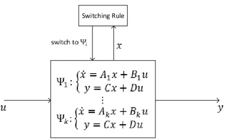
As the smart grid under CSA is considered as a hybrid system we introduce a brief discussion on its stability criteria. The system which contains both continuous and discrete states that influence the dynamic behavior is called Hybrid system or switched system [49], such type of system has its own stability rules, where the stability of all system continuous states is necessary condition but not sufficient to ensure that this system is stable Let us take the hybrid system shown in figure 3.1, the system has N
Switching Rule
Figure 3.1: Hybrid system architecture
continuous states, whereA1, ...,Ak∈Rn×nare the states matrices,B1, ...,Bk∈Rn×mare the input matrices,C∈Rp×nis the output matrix,D∈Rp×mis the feedforward matrix, and u ∈Rm, x ∈Rn and y∈Rp are the input, state and output vectors respectively. The switching decision is taken by switching rule block to switch to state Ψi, where i is an integer i∈[1−N], based on the state vector and it might be based on output vector. Here we have many methods of controlling the hybrid system such as finite time switched control, time average control and sliding mode control (SMC). In this chapter we are more interested in studying SMC because it is the control scheme which is used to control corrupted switch in CSA. SMC is based on designing a sliding surface S(x)force the controlled system trajectory to follow its direction reaching to the desired operating point. To make the mission of designingS(x)easier, we choose S(x)as a linear combination of weighted state variables which is given by:
S(x) =
N
∑
i=1aixi (3.1)
Where ai represent sliding coefficients. SMC problem is summed up by designing these coefficients in such that three conditions are fulfilled, the three conditions are [50], hitting, existence and stability conditions. Hitting condition ensures that the control action will drive the system trajectory toward sliding surface or it’s vicinityε
regardless it’s initial condition, whereε represents the hysteresis band. the following
inequality guarantees this condition: SdS
Existence condition ensures that the system trajectory after hitting the sliding surface it will keep tracking its manifold. Mathematically this condition is represented by:
lim S→0+ dS dt <0 and Slim→0− dS dt >0. (3.3)
Last but not least stability condition ensures that sliding surface not only drives system trajectory toward the equilibrium point, but also it stop this trajectory at the vicinity of this equilibrium point.
3.1.2
Switching Attacks
In order to explain the principles of constructing the switching attacks on smart grid, let us take the following numerical example, suppose we have a system with two state variablesx= x1 x2
this system has two stable statesΨ1 andΨ2as follow
Ψ1: ˙x=A1x, Ψ2: ˙x=A2x (3.4) where A1 = −0.3 2.3 −1 −0.4 and A2 = −2 −2.5 3 1
are the states matrices and
˙ x= dx
dt . As both states have negative real part eigenvalues then the system in its states is stable, and the equilibrium point for both states is(0,0). Figures 3.2a and 3.2b show the system trajectory for both statesΨ1andΨ2respectively.
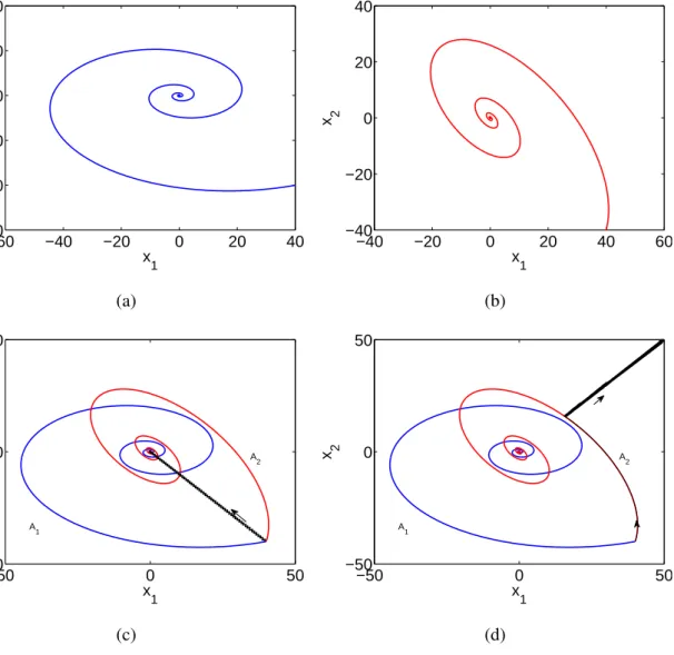
In order to show that the stability of each state of hybrid system is a necessary condition but not enough to ensure the stability of the system [48], let us apply two different sliding surfaces as switching rules to switch between Ψ1 and Ψ2. Both surfaces are designed to satisfy hitting 3.2 and existence 3.3 conditions, however the stability condition is satisfied in the first example and not satisfied in the other, the control signal will be given to the switch or the system to move from one to another state as follow: Switch toΨ1 when S(x)>ε, Switch toΨ2 when S(x)<−ε. (3.5) The system dynamic under first sliding surface applied on the systemS(x) =x1+x2= 0 is shown in figure 3.2c, we can notice that the whole system is stable due to its
−60 −40 −20 0 20 40 −60 −40 −20 0 20 40 x 1 x 2 (a) −40 −20 0 20 40 60 −40 −20 0 20 40 x 1 x 2 (b) −50 0 50 −50 0 50 x 1 x 2 A 1 A 2 (c) −50 0 50 −50 0 50 x 1 x 2 A 1 A 2 (d)
Figure 3.2: System Dynamic. (a) System’s trajectory in StateΨ1. (b) System’s trajectory
in StateΨ2. (c) System trajectory with sliding surfaceS(x) =x1+x2.(d) System trajectory
with sliding surfaceS(x) =x1−x2.
convergence to the common equilibrium point(0,0), moreover, all stability conditions mentioned previously are satisfied where the system is hitting the sliding surface regardless its initial positions and then keeps tracking the vicinity of sliding surface
ε =0.5 and finally stops at the equilibrium point. On the other hand applying another
sliding surface may leads to unstable system like the applied one on the system shown in figure 3.2d, here we can see the system trajectory diverges from the equilibrium point and going to the infinite space with the passage of time, the sliding surface applied isS(x) =−x1+x2=0.
From the previous example we can conclude that the possibility of destabilizing multistructure system is exist even if all its states are stable. The destabilization
process can be achieved by proper designing of switching rule (in our case sliding surface) which controls the hybrid system.
3.2
Cyber Switching Attack Construction
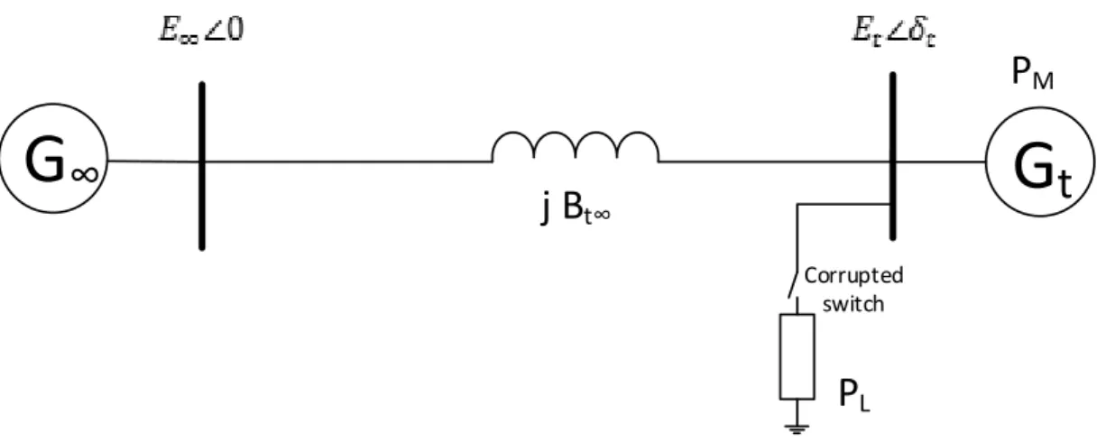
In this section we will try to destabilize a generator (the target generator) which is connected to infinite bus through transmission line, an ohmic load is connected to the target generator bus through breaker (corrupted breaker), figure 3.3 shows the SMIB case. In this study we will assume that the hacker has a full online access to the generator measurements, in other words rotor angleδ and angular speedω or at least
has the online access to the generator measurements which enables him to estimate
δ andω, moreover we assume that hacker gets the authority to control the corrupted
load breaker, these assumptions are to simplify the study and to not go toward the data and communication security of the smart grid. It is important to mention that this section is a reproduction of the researches [28–30] have been done by S.Liu et.al. Let δt and ∆ωt are the deviation of the rotor angle and angular speed of the target generator Gt respectively, Bt∞ is the susceptance of the transmission line between the generator and the infinite bus, Dt represents the damping factor of Gt, Mt is the moment of inertia of Gt, PL and PM are the load power at generator bus and the mechanical power of the target generator respectively , Et and E∞ are the internal voltage of the generator and the voltage of infinite bus respectively.
To represent the dynamics of the target generator we can write the swing equation in
G
∞
G
t
j B
t∞P
MP
L Corrupted switchFigure 3.3: Single machine infinite bus model
form of differential equation as follow: ˙ δt =∆ωt ˙ ∆ωt =M1t[PM−Et2Gtt−σPL−EtE∞Bt∞sin(δt)−Dt∆ωt] (3.6)
where σ represents the situation of the breaker, σ =1 for closed breaker and σ =
0 for opened breaker. Assuming Mt =0.1, Dt =0.1, PL=0.9, PM−Et2Gtt =0.9, EtE∞Bt∞=1 [29]. the overall system can be represented as switched system:
A1: ˙ δt=∆ωt ˙ ∆ωt =−10 sin(δt)−∆ωt i f PLis connected A2: ˙ δt=∆ωt ˙ ∆ωt =9−10 sin(δt)−∆ωt i f PLis NOT connected (3.7)
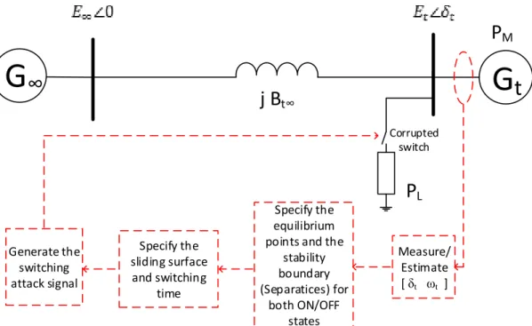
The first step of implementing cyber switching attack is to steal the present situation of the target generator (data attack), or in some cases steal the data which enables the opponent to estimate the required data, in other words to get the initial condition of the system wherex= [δ ∆ω]T is the state variable vector of the studied system. Secondly
to construct the system dynamics, specify the equilibrium points and draw the phase plan of the target generator as well as the stability boundaries (i.e. the separatrices). The third step of the attack is to specify the sliding surface and the attack period,
G
∞
G
t
j B
t∞P
MP
L Measure/ Estimate [ δt ωt ] Specify the equilibrium points and thestability boundary (Separatices) for both ON/OFF states Specify the sliding surface and switching time Generate the switching attack signal Corrupted switch
finally to generate the switching signal and apply this signal on the corrupted breaker. Figure 3.4 presents the diagram of single machine infinite bus with the algorithm of switching attack.
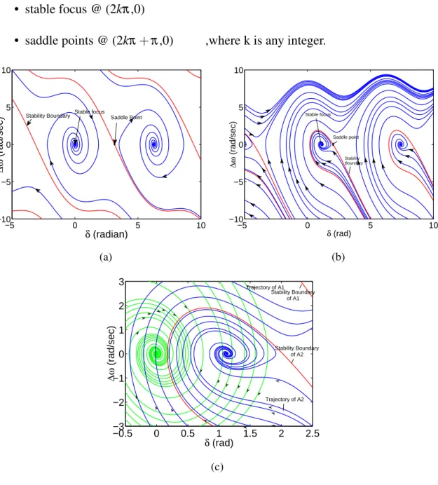
Now we let us analyze each dynamic separately for both breaker positions (opened and closed). When the switch is opened the dynamic of the system is A1, and the system has two types of equilibrium points:
• stable focus @ (2kπ,0)
• saddle points @ (2kπ+π,0) ,where k is any integer.
−5 0 5 10 −10 −5 0 5 10 δ (radian) ∆ω (rad/sec)
Stability Boundary Stable focus Saddle Point
(a) −5 0 5 10 −10 −5 0 5 10 δ (rad) ∆ω (rad/sec) Stable focus Saddle point Stability Boundary (b) −0.5 0 0.5 1 1.5 2 2.5 −3 −2 −1 0 1 2 3 δ (rad) ∆ω (rad/sec) Trajectory of A2 Stability Boundary of A2 Stability Boundary of A1 Trajectory of A1 (c)
Figure 3.5: The dynamics of target generator for different initial conditions. (a) trajectories of system A1 (switch is opened). (b) trajectories of system A2(switch is closed). (c) overlapped trajectories.
On the other hand when the switch is closedA2, then the system also has two types of equilibrium points:
• stable focus @ (2kπ+1.1198,0)
• saddle points @ (2kπ+2.0218,0) ,where k is any integer.
Figure 3.5a and 3.5b show the trajectories of the system and the separatrices (boundary of stability) in both cases (A1 &A2) for different initial conditions, both dynamic’s trajectories are overlapped in figure 3.5c.
Moving to construct cyber switching attack on the target generator, after we assumed that the cyber access to the target generator measurements and the corrupted breaker control is gained by the hacker, then the remain mission is to design the switching signal which will be applied on the corrupted breaker so that the target generator goes out of stability. The main parameters which the switching attack is based on are sliding surface and the period of applying the attack. Sliding surface parameters s(x) =a1δt+a2∆ωt =0 can be chosen such that it satisfies the hitting and existence conditions mentioned in previous section, and ensures that this sliding surface drives the system trajectory away from the the equilibrium point, [30] detects the sliding surface space, we will pick out sliding space parameters from this space as follow: s(x) =1.25δt+∆ωt =0, the switching rule will be:
˙ δt =∆ωt ˙ ∆ωt = −10 sin(δt)−∆ωt, s(x)>ε, 9−10 sin(δt)−∆ωt, s(x)<−ε, (3.8)
The corrupted switch status varies under the attack based on s(x) value, where it is closed whens>0 and opened whens<0. The period of the switching attack can be chosen so that the attack stops switching at the moment when the system trajectory cross the stability boundary for a specific state and to keep the switch on the position of the correspond boundary’s state. To include the breaker delay we will take the hysteresis bandε=0.2.
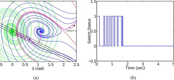
Figure 3.6a presents a success switching attack on the target generatorGt, the system trajectory starts from initial point (where it is assumed that the switch was opened for long period before initiating the attack) and goes away from the origin and going to infinity with the passage of time, which means that the generator is destabilized and the
−0.5 0 0.5 1 1.5 2 2.5 −3 −2 −1 0 1 2 3 δ (rad) ∆ω (rad/sec) Going to ∞ (a) 0 1 2 3 4 5 −0.5 0 0.5 1 1.5 Time (sec) Switch Status (b)
Figure 3.6: Successful cyber switching attack. (a) System trajectory under cyber switching attack. (b) Load switch status.
attack achieve its goal, practically the protection relays switch off the generator after crossing the frequency limit. The switching signal applied on the corrupted switch is shown in 3.6b, the switching signal is applied for 1.7 seconds and then when the system trajectory crosses the boundary of opened switch case, the switch is opened so that the system follows the opened switch dynamic which is out of stability due to cross its boundary.
Applying same sliding surface and hysteresis band i.e. same switching rule,does not necessarily lead to success attack, Figure 3.7 and 3.8 present an unsuccessful
−0.5 0 0.5 1 1.5 2 2.5 −3 −2 −1 0 1 2 3 δ (rad) ∆ω (rad/sec) (a) 0 1 2 3 4 5 −0.5 0 0.5 1 1.5 Time (sec) Switch status (b)
Figure 3.7: Unconstrained cyber switching attack. (a) System trajectory under unconstrained cyber switching attack. (b) Load switch status.
−0.5 0 0.5 1 1.5 2 2.5 −3 −2 −1 0 1 2 3 δ (rad) ∆ω (rad/sec) (a) 0 1 2 3 4 5 −0.5 0 0.5 1 1.5 Time (sec) Switch Status (b)
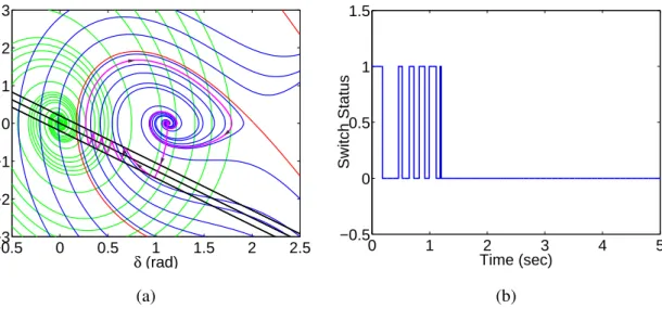
Figure 3.8: Unsuccessful cyber switching attack. (a) System trajectory under unsuccessful cyber switching attack. (b) Load switch status.
switching attacks with same sliding surface applied in previous success attack. In figure 3.7 an unconstrained switching attack with same sliding surfaces(x) =1.25δt+ ∆ωt=0 is applied on the system, the corrupted switch is left to keep switching without time limit, this results in shifting the system equilibrium point from initial stable point
(1.1198,0) to the other one (0,0) which is corresponded to closed switch state. As result the system still stable after the attack and the attack is does not succeed.
Finally if the attack stops switching before the system trajectory crosses the stability boundary, then the system operating point returns back to the initial condition
(1.1198,0)as the system is asymptotically stable inside this region, figure 3.8 shows the system trajectory as well as the corresponding switching signal applied on the corrupted switch.
3.3
Simulation results
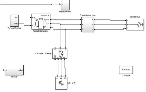
In order to verify the results obtained in previous section we use Matlab-Simulink software, same SMIB system shown in figure 3.3 is implemented on Simulink platform, the generator data has been taken from [30], and shown in table 3.1, the target generator is connected to infinite bus through transmission line has been modeled by inductor with 0.014 H, The generator is loaded by ohmic load, PL = 32.4MW. Figure 3.9 presents the Simulink model used to implement this attack, the
Table 3.1: Target generator parametersGt. Pbase=100 MVA [30]
Parameter Rated voltage Rated power Power factor Frequency
Value 13.8 kV 36 MW 0.8 60 Hz
xd x´d xq Inertia constant T´do
1.55 p.u 0.22 p.u 0.76 p.u. 0.5 sec 8.95 sec
simulation time is 6 seconds.
The simulation results of implementing cyber switching attack on target generatorGt are shown in figure 3.10. A phase plan of target generator rotor angleδ and rotor speed
deviation∆ωis shown in figure 3.10a. Assuming that the system was working for long
period while the switch was opened, consequently the initial conditions[1.098 0]T as it is calculated in previous section.
We can notice how the system trajectory in fig. 4.a starts from the initial condition
[1.098 0]T following the sliding surface until it crosses the stability boundary of the opened switch state and then going to infinity with the passage of time which means the system becomes unstable and the protection relays will disconnect it from the network due to crossing the frequency limit as well as the rotor angle limit. The
Figure 3.9: Simulink model of cyber switching attack on SMIB system
stability boundary is drawn in fig. 4.a is for an opened switch position, the boundary for the closed position is not shown. Driving the operation point of target generator
−2 0 2 4 −10 −5 0 5 10 15 20 δt (rad) ∆ω (rad/sec) (a) 0 0.5 1 1.5 2 0 1 Time (sec)
Corrupted Breaker Status to 6 sec
(b) 0 2 4 6 0 500 1000 1500 Time (sec) δ t (rad) (c) 0 2 4 6 40 60 80 100 120 140 Time (sec) f t (Hz) (d) 0 2 4 6 0 0.5 1 1.5 Time (sec) T e rm in a l V o lta g e ( p .u .) (e)
Figure 3.10: CSA on generatorGt, (a) phase plan, (b) switching signal, (c) rotor angle of
in very fast manner to make big difference between the input mechanical power and the output electrical power is the main reason behind destabilizing the target generator under CSA.
The sliding surfaceS=δt+0.45∆ωt is used to generate the switching signal shown in figure 3.10b, with noticing that the switching process stops att =0.9secdue to cross the boundary of stability. Figures 3.10c and 3.10d show the target generator rotor angle and frequency respectively, it is clear from both figures that the target generator is destabilized due to the attack applied on the corrupted switch and the protection relays have to take action such as disconnecting the target generator from the system where the hacker aim is achieved. The terminal voltage of target generator is shown in figure 3.10e
Chapter 4
Cyber Switching Attack Mitigation
Using TCBR
Thyristor-Controlled Braking Resistor (TCBR) is a member of FACTS controllers family, this controller is usually used to stabilize the power system by absorbing the excess acceleration electrical energy in power network. Due to its resistive nature, TCBR is able only to consume the active power rather than supply it, this characteristic along with TCBRs ability to take a fast action present using TCBR as a cheap, reliable, and dynamical solution for many stability issues. TCBR is widely used to enhance the transient stability, damp low frequency oscillations, damp subsynchronous resonance and solve many other stability problems [54].
A single line diagram of single leg TCBR is shown in figure 4.1, a three phase TCBR consists of three legs each one is connected to phase, and these legs are connected to each other either in wye or delta. Each leg is formed by connecting in series a back-to-back connected thyristor and a resistant RTCBR, practically a transformer is used to connect TCBR to the power grid.
Controlling the consumed power from TCBR can be done by controlling the firing angle of thyristors, the realtion between the average active power consumed by TCBR PTCBR and firing angleα is given by:
PTCBR=
V2 GTCBR
π (π−α+
1
2sin(2α)) (4.1) WhereV is the rms voltage at the point of TCBR connection,GTCBRis the conductance of braking resistor i.e. GTCBR = R 1
TCBR, and α has a range of variation [0,π]. The
G
TCBRT
Figure 4.1: Single line diagram of one leg TCBR
increasingα till reaching zero atα =π.
Our proposed method of mitigating CSA is based on fixing TCBR at the target generator terminals, the objectives of TCBR is to absorb the accelerating active power that produced after CSA which is the main reason of destabilizing the target generator as it is mentioned in previous chapter.
Figure 4.2a shows the proposed method, the generator frequency, mechanical input power and electric output power are fed to the controller, the controller specifies the appropriate firing angle based on the required energy to be absorbed by TCBR. Firing angleα is fed to pulses generator which in turn trigger TCBR thyristors. After adding
TCBR to the system the system dynamic can be represented by:
dδ dt =∆ω M d2δ dt2 =Pm−Pe−Pd−PTCBR (4.2)
The controller structure is shown in figure 4.2b the difference between the input mechanical power Pm and the output electrical power is calculated and fed to PID controller, which in turn produce the required conductance of TCBR Gout to absorb the acceleration active power. whereGout is calculated as follow:
Gout =
GTCBR
π (π−α+
1
2sin(2α)) (4.3) The required conductance is limited between zero and nominal conductance value GTCBR. Equation 4.2 then is used to calculate the required firing angle which is limited
in the range of[0,π]. TCBR controller works only when the generator accelerate and
its speed deviation cross 2% of the nominal speed, otherwise TCBR does not consume any power i.e. α =π.
We use Matlab/Simulink to check the efficiency of proposed method in mitigating CSA, the attack implemented in previous section is applied on the system with simulation time 15 sec with same sliding surface S =δt+0.45∆ωt and switching time t =0.9sec. The rated conductance of TCBR is GTCBR =0.15pu with Pbase = 100MVA and Vbase =13.8kV. The conduction and switching losses in TCBR’s thyristors are neglected compared with the power consumed by the braking resistor. The simulation results are presented in Figure 4.3
G
∞
j xG
t
t∞ PL TCBR Pulses Generator Controller Control Center Measurements Pe PM α* ω P*M (a) PID Gmax Gmin G α -+ Pe α1 If Δω< +2% α* = 180◦ Else α* = α2; -+ ωmeas ωref Δω Limiter α2 PM Controller ΔP Gout Limiter αmax αmin α* (b)Figure 4.2: Using TCBR to mitigate CSA (a) closed loop control of TCBR, (b) the controller structure.
0 0.5 1 1.5 2 −10 −5 0 5 10 δ (rad) ∆ω (rad/sec) (a) 0 5 10 15 0 0.2 0.4 0.6 0.8 1 1.2 1.4 Time (sec)
Terminal Voltage (pu)
(b) 0 5 10 15 0 0.5 1 1.5 2 Time (sec) δ (rad) (c) 0 5 10 15 59 60 61 Time (sec) f (Hz) (d) 0 5 10 15 −0.25 −0.2 −0.15 −0.1 −0.05 0 Time (sec) P TCBR (pu) (e)
Figure 4.3: Simulation results of SMIB system under CSA in the presence of TCBR. (a) System phase plan. (b) The terminal voltage of target Generator. (c) The frequency of target Generator. (d) Rotor angle of target Generator. (e) Active power consumed by TCBRPTCBR.
Figure 4.3a shows the phase portrait of target generator dynamic, the generator was attacked by CSA and trajectory started to diverge away from the equilibrium point. When the rotor speed deviation crosses the specified limit i.e. ∆ω =2%∗120π =
7.54rad/sec, TCBR intervenes and starts to consume the excess acceleration power specified from the difference between Pm and Pe, the consumed power by TCBR is shown in figure 4.3e. We can notice from the phase plan that the intervention of TCBR restore the system stability and draw the system trajectory to new equilibrium point, the location of this equilibrium point can be specified from equation 4.2 and can be controlled by changing the consumed power from TCBRPTCBRwhich can be done by tuning the PID controller parameters.
The rotor angle ,terminal voltage, and frequency of the target generator are shown in figures 4.3b, 4.3c, 4.3d respectively, we can notice from both rotor angle and frequency curves that the system recaptures the stability in less than 10 seconds after the CSA. The time of stability can be minimized by increasing the rated power of TCBR, but practically it is not efficient action due to the increase of TCBR cost.
Chapter 5
Conclusion And Future Work
5.1
Conclusion
A literature survey on cyber attacks on smart grids has been presented, a preface about the importance of smart grids and the probable risks of the interconnection between the communication layer and power network in smart grids has been introduced in the first chapter. A literature survey on the cyber attacks which are directed to destabilize the power layer of smart grid has been introduced in the second chapter, this chapter surveyed also the works have been done on cyber attack detection and identification. In third chapter a full description of cyber switching attacks on smart grids has been presented, single-switch attacks has been discussed in details in this part, we have simulated and discussed a case study of single machine infinite bus, a detailed description of implementing cyber switching attack has been presented on the case study, the result shows that successful switching attack can destabilize the target machine in less than one second. In chapter four of the study, a new solution to save the stability of target generator has been introduced, the suggested solution is based on using TCBR to prevent the attack from destabilizing the target generator. Finally, in this chapter, the thesis is concluded and future work is presented.
5.2
Future Work
• To include the turbine action of target generator in calculating the rated power of TCBR.
• To develop a controller that cooperate between the turbine and TCBR, so that the rated power of TCBR can be reduced.
• To study cyber switching attack on multi-machine system, and specify the optimal location and number of TCBR controllers to mitigate the most savior scenario.
• To develop a new type of coordinated cyber attack which combines congestion and switching attack.
Bibliography
[1] Environmental Engineering (EE) The use of alternative energy solutions in
telecommunications installations ETSI,V1.2.1 (2012-11) , European Telecommunications
Standards Institute 2012.
[2] Smart Grid Insights. South Korea: Smart Grid Revolution, Zpryme Research and
Consulting, July 2011.
[3] E. Widl, P. Palensky, P. Siano, and C. Rehtanz, Guest Editorial: Modeling, Simulation,
and Application of Cyber-Physical Energy Systems.IEEE Trans. Industrial Informatics,
vol. 10, no. 4, pp. 2244-2246, (2014).
[4] Lloyds of London and University of Cambridge, Business Blackout: The insurance
implications of a cyber attack on the US power grid, May 2015. Avilable
at:www.cambridgeriskframework.com/getdocument/29.
[5] M. E. Kantarci and H. T. Mouftah,Smart grid forensic science: Applications, challenges,
and open issues,IEEE Commun. Mag., vol. 51, no. 1, pp. 68-74, Jan. 2013.
[6] Z. Zhang, L. Hao, N. Shuangxia, and Mo Jiansong. Information security requirements
and challenges in smart grid.In 6th IEEE Joint International Information Technology and
Artificial Intelligence Conference (ITAIC), vol. 1, pp. 90-92. 2011.
[7] W. Wang and Z. Lu,Cyber security in the smart grid: Survey and challenges,Comput. Netw., vol. 57, no. 5, pp. 1344-1371, 2013.
[8] X. Li, X. Liang, R. Lu, X. Lin, H. Zhu, and X. Shen,Securing smart grid: Cyber attacks,
countermeasures and challenges, IEEE Communications Magazine, vol. 50, no. 8, pp.
38-45, 2012
[9] I. H. Lim, S. Hong, M. S. Choi, S. J. Lee, T. W. Kim, S. W. Lee, and B. N. Ha, Security
protocols against cyber attacks in the distribution automation system, IEEE Trans.
Power Del., vol. 25, no. 1, pp. 448-455, Jan. 2010.
[10] C.-W. Ten, J. Hong, and C.-C. Liu, Anomaly detection for cybersecurity of the
substations,IEEE Trans. Smart Grid, vol. 2, no. 4, pp. 865-873, Dec. 2011.
[11] S. Sridhar, A. Hahn, and M. Govindarasu,Cyber-physical system security for the electric
power grid,Proc. IEEE, vol. 100, no. 1, pp. 210-224, Jan. 2012
[12] P. Mohajerin Esfahani, M. Vrakopoulou, K. Margellos, J. Lygeros, and G. Andersson,Cyber
attack in a two-area power system: Impact identification using reachability, in Proc.
Amer. Control Conf. (ACC), 2010.
[13] S. Liu, X. Liu, and A. El Saddik, Denial-of-Service (DoS) attacks on load frequency
control in smart grids,in IEEE PES Innovative Smart Grid Technologies (ISGT), pp. 1-6,
2013.
[14] S. Sridhar and G. Manimaran, Data integrity attacks and their impacts on SCADA
control system,in Proc. Power Energy Soc. Gen. Meet., 2010
[15] Jia, Hongjie, Xiaodan Yu, Yixin Yu, and Chengshan Wang. Power system small signal
stability region with time delay. International Journal of Electrical Power & Energy
Systems 30, no.1 (2008): 16-22.
[16] H. Wu, H. Ni, and G. T. Heydt, The impact of time delay on robust control design in
power systems,in Proc. IEEE PES Winter Meeting, vol. 2, pp. 27-31, 2002.
[17] R. Liu, C. Vellaithurai, S. S. Biswas, T. T. Gamage, and A. K. Srivastava, Analyzing the
Cyber-Physical Impact of Cyber Events on the Power Grid,IEEE Trans. on Smart Grid,
vol. 6, no. 5, pp. 2444-2453, Sep. 2015.
[18] S K. Sgouras, A. Birda, and D. Labridis, Cyber attack impact on critical smart grid
infrastructures,in IEEE PES Innovative Smart Grid Technologies Conference (ISGT), pp.
1-5, Feb. 2014.
[19] B. Chen, K. L. Butler-Purry, S. Nuthalapati, and D. Kundur, Network Delay Caused by
Cyber Attacks on SVC and its Impact on Transient Stability of Smart Grids,in Proc.
IEEE Power and Energy Society General Meeting (PES), pp. 1-5, 2014.
[20] R. Olfati-Saber, Flocking for multi-agent dynamic systems: Algorithms and theory,
IEEE Trans. Autom. Control, vol.51, no. 3, pp. 401-420, Mar. 2006.
[21] J. Wei, D. Kundur, T. Zourntos, and K. Butler-Purry, A flocking based paradigm for
hierarchical cyber-physical smart grid modeling and control, IEEE Trans. Smart Grid,
vol. 5, no. 6, pp. 2687-2700, Nov. 2014.
[22] J. Wei and D. Kundur,Two-tier hierarchical cyber-physical security analysis framework
for smart grid,in Proc. IEEE Power Energy Soc. Gen. Meeting (PESGM), San Diego, CA,
USA, Jul. 2012, pp. 1-5.
[23] J. Wei and D. Kundur, A multi-flock approach to rapid dynamic generator coherency
identification,in Proc. IEEE Power Energy Soc. Gen. Meeting, Vancouver, BC, Canada,pp.
1-5 , Jul. 2013.
[24] A. K. Farraj, E. Hammad, J. Wei, D. Kundur, and K. Butler-Purry, Performance
of Flocking-Based Control Schemes in Smart Grid Applications, in IEEE Global
Conference on Signal and Information Processing (GlobalSIP), pp. 1-5, December 2014. [25] A. Farraj, E. Hammad, and D. Kundur,A Cyber-Enabled Stabilizing Control Scheme for
Resilient Smart Grid Systems,IEEE Trans. on Smart Grid, no. 99, pp. 1-10, 2015.
[26] E. Hammad, A. Farraj, and D. Kundur, A Resilient Feedback Linearization Control
Scheme for Smart Grids under Cyber-Physical Disturbances,in IEEE PES Conference
on Innovative Smart Grid Technologies (ISGT), pp. 1-5, February 2015.
[27] V. Nasirian, S. Moayedi, A. Davoudi, and F. Lewis, Distributed Cooperative Control of
DC Microgrids,IEEE Trans. Power Electron., vol. 30, no. 4, pp. 2288-2303, 2015.
[28] S. Liu, X. Feng, D. Kundur, T. Zourntos, and K. Butler-Purry, Switched system models
for coordinated cyber-physical attack construction and simulation, In First IEEE
International Workshop on Smart Grid Modeling and Simulation, Brussels, Belgium, October 2011, pp. 4954.
[29] S. Liu, X. Feng, D. Kundur, T. Zourntos, and K. L. Butler-Purry,A Class of Cyber-Physical
Switching Attacks for Power System Disruption, in Cyber Security and Information
Intelligence Research Workshop (CSIIRW), pp. 14, 2011.
[30] S. Liu, S. Mashayekh, D. Kundur, T. Zourntos, and K. Butler-Purry, A framework for
modeling cyber-physical switching attacks in smart grid,IEEE Trans. Emerging Topics
Comput., vol. 1, no. 2, pp. 273285, 2013.
[31] S. Liu, D. Kundur, T. Zourntos, and K. L. Butler-Purry,Coordinated Variable Structure
Switching Attack in the Presence of Model Error and State Estimation, in IEEE
International Conference on Smart Grid Communications (SmartGridComm), pp. 318323, 2012.
[32] S. Liu, S. Mashayekh, D. Kundur, T. Zourntos, and K. L. Butler-Purry, A Smart Grid Vulnerability Analysis Framework for Coordinated Variable Structure Switching
Attacks,in IEEE Power and Energy Society General Meeting, pp. 16, 2012.
[33] A. Farraj and D. Kundur, On Using Energy Storage Systems in Switching Attacks That
Destabilize Smart Grid Systems, in IEEE PES Conference on Innovative Smart Grid
Technologies (ISGT), pp. 1-5, February 2015.
[34] A. Farraj, E. Hammad, D. Kundur, and K. Bulter-Purry, Practical Limitations of
Sliding-Mode Switching Attacks on Smart Grid Systems, in IEEE Power and Energy
Society General Meeting (PESGM), pp. 1-5, July 2014.
[35] S. Liu, B. Chen, T. Zourntos, D. Kundur, and K. Butler-Purry,Progressive switching attacks
for instigating cascading failures in smart grid. in IEEE Power and Energy Society
General Meeting, pp. 15, 2013.
[36] S. Liu, B. Chen, T. Zourntos, D. Kundur, and K. Butler-Purry,A coordinated multi-switch
attack for cascading failures in smart grid, IEEE Trans. Smart Grid, vol. 5, no. 3, pp.
11831195, May 2014.
[37] A. Farraj, E. Hammad, and D. Kundur,On Using Distributed Control Schemes to Mitigate
Switching Attacks in Smart Grids. in IEEE 28th Canadian Conference on Electrical and
Computer Engineering (CCECE), pp. 1578-1582, May 2015.
[38] A. Farraj, E. Hammad, A. Al Daoud, and D. Kundur,A game theoretic analysis of cyber
switching attacks and mitigation in smart grid systems,IEEE Trans. Smart Grid, 2015.
[39] S.Z. Yong, M. Zhu, and E. Frazzoli,Resilient state estimation against switching attacks
on stochastic cyber-physical systems.in IEEE International Conference on Decision and
Control. 2015.
[40] S. Liu, D. Kundur, T. Zourntos, and K. Butler-Purry, Coordinated variable structure
switching in smart power systems: Attacks and mitigation, in 1st International
Conference on High Confidence Networked Systems, China, April 2012.
[41] F. Pasqualetti, R. Carli, and F. Bullo.Distributed estimation and false data detection with
application to power networks,Automatica, March 2011,
[42] D. Wang, X. Guan, T. Liu, Y. Gu, C. Shen, and Z. Xu, Extended distributed state estimation: A detection method against tolerable false data injection attacks in smart
grids,Energies, vol. 7, no. 3, pp.1517-1538, 2014.
[43] A. Mohsenian-Rad and A. Leon-Garcia, Distributed internet-based load altering attacks against smart power grids, IEEE Transactions on Smart Grid, vol. 2, no. 4, pp. 667-674, 2011.
[44] F. Pasqualetti, F. Dorfler, and F. Bullo, Attack detection and identification in
cyber-physical systems Part I: Models and fundamental limitations,arXiv:1202.6144v2,
2012.
[45] F. Pasqualetti, F. Dorfler, and F. Bullo, Attack detection and identification in
cyberphysical systems part ii: Centralized and distributed monitor design,
arXiv:1202.6049, 2012.
[46] F. Dorfler, F. Pasqualetti, and F. Bullo, Distributed detection of cyber-physical attacks
in power networks: A waveform relaxation approach, in Proc. 49th Annual Allerton
Conference on Communication, Control, and Computing, pp. 1486-1491, 2011.
[47] F. Pasqualetti, A. Bicchi, and F. Bullo, A graph-theoretical characterization of power
network vulnerabilities, in American Control Conference, San Francisco, CA, USA, pp.
3918-3923, 2011.
[48] D. Liberzon,Switching in Systems and Control. Boston: Birkhauser,2003.
[49] S. Pettersson and B. Lennartson, Hybrid system stability and robustness verification
using linear matrix inequalities,Inter.J. Control, vol. 75, no. 16-17, pp. 1335-1355, 2002.
[50] S.-C. Tan, Y.-M. Lai, and C. K. Tse, Sliding Mode Control of Switching Power
Converters. Boca Raton, FL, USA: CRC Press, 2011.
[51] P. W. Sauer and M. A. Pai, Power System Dynamics and Stability. Upper Saddle River, NJ: Prentice-Hall, 1998.
[52] P. Kundur,Power System Stability and Control. New York: McGrawHill, 1994.
[53] J. Machowski, J. Bialek, and J. Bumby,Power System Dynamics: Stability and Control, 2nd ed. NJ, US: John Wiley & Sons, Inc. 2008
[54] N. G. Hingorani and L. Gyugyi, Understanding FACTS: Concepts and Technology of
Flexible AC Transmission Systems, New York: IEEE Press, 2000.
[55] A. H. M. A. Rahim and D. A. H. Alamgir,A closed-loop quasi-optimal dynamic braking
resistor and shunt reactor control strategy for transient stability, IEEE Trans. Power
Syst., vol. 3, no. 3, pp. 879-886, Aug. 1988.
[56] M. H. Ali, T. Murata, and J. Tamura, Effect of coordination of optimal reclosing and fuzzy controlled braking resistor on transient stability during unsuccessful reclosing,

![Table 2.1: Classification of cyber attacks in smart grid [8].](https://thumb-us.123doks.com/thumbv2/123dok_us/1359263.2681872/18.892.185.734.616.982/table-classification-cyber-attacks-smart-grid.webp)