Trimarg: A Distributed Algorithm for the Formation of
Highly Available Underlay Aware Overlay Networks of
Event Brokers
Madhu Kumar S D
Department of Computer Science and Engineering
Indian Institute of Technology Bombay India
[email protected]
Umesh Bellur
Department of Computer Science and Engineering
Indian Institute of Technology Bombay India
[email protected]
ABSTRACT
Event broker networks are used to interconnect publishers and sub-scribers in an event based distributed computing system. Event broker networks are overlay networks formed over the underlying physical network (underlay). In modern distributed applications, high availability in the presence of the runtime failures is an im-portant concern. This paper presents an asynchronous distributed algorithm for constructing and maintaining an underlay aware over-lay which ensures 3-degree of availability in the presence of node and link failures in the underlying physical network. We prove the-oretically that our algorithm is correct. The time complexity of our algorithm is estimated to beO(diameter∗degree)2 of the net-work and the message complexity isO(diameter∗degree). We have investigated the scalability of the algorithm on a simulation testbed. The preliminary scalability test results demonstrate the scalability of our method.
Categories and Subject Descriptors
C.2.4 [Computer-Communication Networks]: Distributed Sys-tems; D.2.8 [Software Engineering]: Metrics
General Terms
Availability, Event Based Systems
Keywords
Overlay Networks, Triconnectivity, Underlay Awareness, Avail-ability
1. INTRODUCTION
Event broker networks are used for event dissemination in large scale event based applications. Event brokers[1] form an overlay network over the physical network consisting of broker nodes as well as other (non-broker) nodes. Overlay networks facilitate appli-cations to run smoothly without being aware of, and disturbed by, the intricacies and variations of the underlying network. In order
to provide this support to applications, the overlay network should ensure the availability of routing paths in the event of node and link failures in the underlying physical network. The overlay has to be formed and maintained dynamically, while the event broker soft-ware and applications are running. As the network of computers is an asynchronous distributed system, asynchronous algorithms are required for the formation and maintenance of overlay networks. This paper outlines an asynchronous distributed algorithm for the construction and maintenance of an overlay network which guaran-tees the existence of three physically node disjoint paths between every pair of overlay nodes. Such an overlay network can be used for routing events without any changes in the presence of two node failures or two link failures, i.e., having an availability of degree three [2]. We chose to focus on an availability of degree three as higher degrees of availability would place a constraint of higher physical degrees (network connections) on the broker nodes in the network. The concept of our algorithm can be extended to provide availability of higher degrees.
The paper is organized as follows. Section 2 describes event bro-ker networks, availability in event brobro-ker networks and the concept of underlay awareness. Related work on available overlays is pre-sented in Section 3. Section 4 illustrates the graph theoretic concept of triconnected graphs, which is closely related to overlays of avail-ability three. TheTrimargalgorithm design and analysis form Sec-tion 5. SecSec-tion 6 presents the proof of correctness for theTrimarg
algorithm. Sections 7 and 8 describe the experimental framework for carrying out the simulation studies and present our experimen-tal results. Future work in this area is discussed in Section 9, which also concludes the paper.
2. BACKGROUND
2.1 Event Broker Networks
In a distributed event processing system [1], event publishers and event subscribers are clients which are connected through a set of event brokers. In a multi-broker publish-subscribe system these event brokers are connected in a peer to peer fashion[1] to form an overlay network over the underlying physical network (under-lay)[3].
Event brokers are smart machines where the event based middle-ware softmiddle-ware is installed. The network of event brokers basically forms a sub network of the underlay network. An overlay network is a logical abstraction of the underlying physical network and can be represented as a graph with vertices corresponding to the
over-lay nodes and edges corresponding to the overover-lay paths between the pairs of overlay nodes. Multiple overlays can be constructed based on a single physical network. An overlay network can be represented as a graphN =< B, L >, where the vertex set B is the collection of overlay nodes, and the edge set L is the collection of paths between overlay node pairs that are determined by the ap-plication (in this case the event broker network). Each broker can directly communicate only to its neighbouring brokers, to which it has direct overlay links. This overlay network of brokers can be structured in many ways. Standard graph topologies like ring, tree, star, chordal ring[4] etc. are seen in literature. However, the per-formance of such an overlay network is tightly linked to that of the underlying physical network (also termed underlay).
In order to maintain a specific quality of service and to be ro-bust, the event based middleware forming the overlay must adapt to changing conditions both in the application requirements and changes in the computation and communication infrastructure pro-vided by the underlying physical network of computers. Amongst changes that can happen in the environment, physical node failure and link failure are crucial as they may block the communication to clients, if there are no alternate paths readily available or effi-ciently computable in the network [4]. The overlay needs to be underlay aware so that it adapts itself to the faults or failures that occur in the underlay. The main focus of this paper is on improving availability in event based systems by providing an overlay network that is adaptable to node and link failure triggers[4]. The proposed overlay is a general fault tolerant overlay which can be used for event dissemination in event based middleware. We propose a dis-tributed algorithm for formation and maintenance of an underlay aware, available overlay formation for the event broker network. The next subsection briefly describes the model of availability in Event Broker Networks used in this paper.
2.2 Availability in Event Broker Networks
Availability of a system is defined in standard literature as the frac-tion of time for which a system is up (usable). In [2] the availability of a general network is discussed and the degree of availability of a network is defined and related to the node connectivity of a net-work. According to [2] a network with an availability of degree k has probability of non-availability of a path between any two pair of nodes as(1−(1−p)n)k, where n is the average path length, and
p is the probability of failure of a link. Such a network should have a topology that guarantees the existence of k independent paths be-tween any pair of nodes. In this paper, we extend the definition of availability and model it for overlay networks. In the context of event broker networks, the availability of the overlay network is the primary concern and the availability of the physical network is of consequence only to the extent of the influence it has on the availability of the overlay network.
2.3 Underlay Awareness
Clearly, knowledge of all aspects of the physical network cannot be known by the overlay network as:
1. A centralized repository of information is not generally main-tained. The information is distributed, as is the network.
2. The underlying network changes dynamically and hence main-taining current information at all nodes is difficult and resource-consuming.
3. The magnitude of information is large and storing this at every
broker node is not practical.
[5] Provides a taxonomy of overlay networks and classifies under-lay aware networks as proximity aware and quality aware. Proxim-ity aware overlays are aware only of neighborhood distance infor-mation. Quality aware networks are aware of other aspects of the links from the node, such as disjointness and performance parame-ters.
In this paper we describe algorithms for anunderlay quality aware overlay. The overlay nodes gather and store information about the underlying path for the overlay links originating from them includ-ing information about the nodes in the path and information about the node overlap in the overlay links from the node. However, the magnitude of this information is reduced by the fact that this in-formation is required only for the nodes that “matter” in the path. We present a brief classification of the nodes in the physical graph relevant in this context.
2.3.1
Node Classification
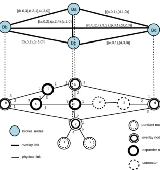
All the nodes in the graph may be classified as follows - overlay nodes, expander nodes, connector nodes and trivial nodes. Figure 1 illustrates this concept.
Overlay nodes Overlay nodes are the nodes selected to be brokers. They should satisfy the criterion that their physical degrees are greater than or equal to k, where k is the degree of con-nectivity required.
Expander nodes Expander nodes are nodes (non brokers) with degree more than two. They have the potential to exist in more than one physical path. Hence any overlay link that contains such nodes can overlap with other overlay links, which contain the same expander node. Hence overlay nodes should remember such nodes that exist in their overlay links.
Connector nodes These nodes have degree equal to two. They cannot be a part of more than one path between two higher degree nodes and are hence ”collapsible” as far as disjointed-ness studies are considered, unless their degrees get changed.
Trivial or client nodes These correspond to “pendant” nodes in graph theory terminology and have a degree of just one. They cannot be guaranteed a connectivity more than one, and can serve only as client nodes, if at all, in an overlay of connec-tivity k higher than one. Hence these nodes can be ignored for overlay construction.
2.3.2 Link numbering
The links associated with every node in the physical network are ordered and specified by their link number for the node. For exam-ple, a node with degree five has a fixed ordering 1, 2, 3, 4, and 5 for its outgoing links. The ordering is fixed based on a function of link type and bandwidth, and uniquely determinable for every node.
2.3.3
Underlay information
The overlay node stores a sequence of three tuples for each of its overlay links. The three elements of the tuple are (node-id, link1, link2), wherenode-ididentifies the physical nodes in the sequence, andlink1andlink2are the link numbers of the links of the node. The end nodes in this sequence correspond to broker nodes and the intermediate nodes are expander nodes. Connector nodes are not
p a d b c 1 2 3 1 2 3 1 2 3 1 2 3 1 3 2 4 w z 1 2 3 1 2 3 k r s t 4 5 Bb Ba Bd Bc pendant nodes overlay nodes expander nodes connector nodes [(b,0,3),(t,2,1),(a,3,0)] [(a,0,1),(d,1,0)] [(b,0,1),(c,3,0)] [(c,0,1),(d,3,0)] [(b,0,2),(s,3,1),(p,3,1),(d,2,0)] [(a,0,2),(p,2,4),(c,2,0)] broker nodes overlay link physical link
Figure 1: Types of nodes in the underlying network
included as they cannot possibly overlap. Pendant nodes cannot be a part of such a path. This information is used by the broker nodes for overlay construction. In the next section we present two different perspectives of available overlays.
2.3.4 Underlay Aware Available Overlays
A given physical network can form the basis for many overlays net-works. The availability guaranteed by an overlay can be manifested in two ways. It may be explicit, which means that different paths that are node disjoint in the overlay also map to physically node disjoint paths. On the other hand, an overlay’s availability may be implicit, or hidden, which means that node disjoint overlay paths are not necessarily node disjoint at the physical level, but the exis-tence of different node disjoint paths at the underlay level, for each pair of overlay nodes, is guaranteed by the overlay. On this basis we classify available overlays as
1. Manifest 2. Latent p a d c q Bq w Bw Ba Bd Physical node Overlay node Overlay Link Physical Link
Figure 2: Availability Manifest Overlay
Availability Manifest Overlay:AnAvailability Manifest Overlay
can be defined as follows. LetG=< V, E >represent a physical network, andN =< B, L >be an overlay network based onG, whereB⊆VandLconsists of overlay links which are paths in G between two vertices ofGthat also belong to B. N represents an availability manifest overlay network, if for any two nodesb1and
b2belonging to B, if(b1, x1...xk, b2)and(b1, y1...yk, b2), where
x1..xk, andy1..yk, all are broker nodes, be two overlay paths
be-tween b1 and b2 such thatx1..xkandy1..ykare disjoint sets, then
the two paths are also disjoint at the underlay level. In other words, the set(p1, x1, p2, x2...pk, xk)and the set(q1, y1, q2, y2...qn, yn),
wherep’s andq’s represent the physical nodes along the path, are also disjoint sets. This is illustrated in Figure 2. Given a physical network and an overlay graph, constructing an availability manifest overlay on the physical graph can be directly mapped to the fixed, node disjoint subgraph homeomorphism problem[6], which is NP-complete for general subgraphs (overlays). However for simple subgraphs, such as triangles and two node disjoint paths between two nodes, the fixed, node disjoint subgraph homeomorphism prob-lem has linear time solutions [6],[7]. Manifest overlaycreation re-quires a complete knowledge of the underlay, which is a practically difficult proposition in the context of event broker systems. More-over,manifest overlaysare not absolutely necessary if availability is the only requirement. Hence, we focus onlatent overlays.
p a d b Bb Ba Bd Bc c Physical node Overlay node Overlay Link Physical Link
Figure 3: Availability Latent Overlay
Availability Latent Overlay:Anavailability latent overlayof de-gree of availability k on a graph< V, E >is defined asA =<
B, L >, where B is a subset of V, and L is a set of links which
rep-resent paths in the physical network, and for any(b1, b2)belonging to B, there exist k node disjoint paths in the physical network be-tween the nodes corresponding to b1 and b2. This is illustrated in Figure 3. Hence in anavailability latent overlay, two distinct overlay links can have node overlaps, but between any two broker nodes, k node disjoint paths are guaranteed.
3. RELATED WORK
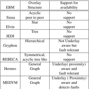
Event based Middleware is a well studied area and a number of re-search projects have been carried out in this field. Our survey on the EBM research projects and study of the type of overlay networks used and their support for availability is summarized in Table 1.
Overlay Support for EBM Structure availability
Acyclic No Siena peer to peer support
Star No
Elvin support
Tree No
JEDI support
Hierarchical Not Underlay Gryphon aware but
fault tolerant Symmetrical, No REBECA acyclic tree like support
General Underlay( proximity) Hermes Graph aware and
fault tolerant General Underlay ( Proximity) MEDYM Graph aware and
detects faults
Table 1: Availability in overlay networks of current EBM projects
The research projects studied here are Hermes[1], Siena [8], JEDI[9], REBECA[10], Elvin[11], MEDYM[12] and Gryphon[13]. Pastry [14] uses a distributed hashing technique for the overlay forma-tion and is not underlay quality aware. The Padres[15] project fo-cuses on composite event handling and is not explicit on the over-lay topology used for the event broker network. RON[16] outlines a strategy for recovering from outages by finding alternate paths via different overlay paths exploiting the “redundancy” present in the Internet for distributed applications. Our survey indicates that the current research on event based middleware has not given suf-ficient attention to available overlay formation. Also distributed algorithms do not exist at present for the creation and maintenance of available overlays for broker networks. [2] contributes a formal definition of availability of overlay networks and presents BICON, an available network of degree two. BICON is anavailability man-ifest overlayof fixed availability of degree two. However, as the manifest availability criterion is difficult in a practical network, we explore availability latent solutions.
In the next section we discuss the concept of triconnectivity in graphs, which forms the basis for our algorithm.
4. TRICONNECTIVITY IN GRAPHS
Ak-connected (or k node connected) undirected graph G =<
V, E >is such that there are k pairwise node disjoint paths between
every pair of nodes in V.
Whitney’s theorem [17], a fundamental theorem in graph theory states that the node connectivity of a graph cannot be more than the minimum degree among all the nodes. Hence a graph cannot have a connectivity and thereby a degree of availability more than the degree of its lowest degree node. If the graph represents a phys-ical network of computers, nodes of degree greater than three are rare, as it would entail more than three network connections per machine. Hence, we focus on 3-connected graphs, which are also calledtriconnectedgraphs [7].
Aseparation pair[17] is a vertex pair (a,b) of a connected graph such that the subgraph G’ of G induced by V-{a,b}is disconnected.
s1 s3
s2
s0
Figure 4: The Stellar Broker Network
If (a,b) is a separation pair of G, then there are at least two nodes x and y in G such that every path between x and y passes through either a or b or both. A triconnected graph has no separation pairs.
Aseparating cut[17] is a set of verticesVcof a connected graph
such that the subgraph G’ of G induced byV−Vcis disconnected.
Aseparating cutof a triconnected graph has at least three vertices.
In general, if a node is added to a triconnected graph in such a manner that it is not disconnected by a separation pair, the resultant graph will be triconnected. This means that it will not be discon-nected from the network by the removal (failure) of two nodes or one node. This can be ensured by connecting it by distinct edges to three different nodes of the original triconnected graph.
TheTrimargalgorithm, discussed in the next section is based on the same principle.Trimarg, in Sanskrit, means three paths. The concept of the algorithm can be used to build similar algo-rithms for higher degrees of availability with different complexities. We develop and present an algorithm for a connectivity of three as higher degrees of connectivity pose a more impractical constraint of greater physical connectivity on the physical nodes in the net-work.
5. THE TRIMARG ALGORITHM
We start with the design fundamentals of our algorithm.
5.1 Design
The overlay network is initialized with four special broker nodes called thestellarnodes. The stellar nodes network form a wheel [17] network of four nodes. The edges in the wheel network are physically disjoint. This network is statically designed and initial-ized. The stellar broker network is illustrated in Figure 4. Figure 5 shows the underlying physical network of the stellar broker net-work.
The initial (stellar) broker hasmanifestandlatent availabilityof degree three, as can be observed by listing out the paths between broker pairs in Figure 5. The paths contain expander nodes as well as connector nodes. The identities of the expander nodes in the ad-jacent links are stored at the broker nodes. A node that wishes to join the overlay network of broker nodes does so by connecting
it-s1 s3 s2
s0
Figure 5: The Stellar Broker network structure
s1 s3
s2
s0
x B
Figure 6: A node joining the existing overlay network
self to existing broker nodes. The overlay links so formed need not necessarily be node disjoint with existing links. However, the bro-ker network should ensure that the new brobro-ker has three pairwise node disjoint paths to every broker node in the existing network.
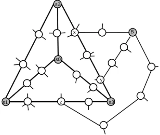
The node joins the overlay network through links consisting of pos-sibly many expander nodes in the link. Consider the expander node x, which is the first node in this path which is already a part of the existing overlay network’s underlay, as illustrated in Figure 6.
At this stage,xis a separating cut of the new broker network, as it disconnects B from the network. The separating cut is of size one. The old network is known to have no separating cuts of size less than three. If now, node B is linked to the existing network through another existing expander node y, the cut separating B from the remaining nodes will bex, y. A third connection to z for B should ensure that the separating cut of B from the existing overlay is three or greater. The two cases that may arise due to relative positions of x an y in the network.
1. Case 1: The nodexandylie on common overlay link.This is illustrated in Figure 7. The new link from B to the broker net-work (to nodez) should lie on a different overlay link, other than the one having x and y in it, otherwise the node B has a separating cut of size two. Figure 7 illustrates this. Thus another link needs to be found, such that it meets a different
overlay link, like z, to ensure the availability constraints.
s1 s3 s2 s0 x B y z
Figure 7: Relative positions of joining expander nodes - case 1
2. Case 2: The nodex, yandz lie on different overlay links. The size of separating cut is at least three. This is illustrated in Figure 8. s1 s3 s2 s0 x B y z
Figure 8: Relative positions of joining expander nodes - case 2
The steps in the distributed algorithm work as follows. The new node to join is statically aware of the ids of the stellar broker nodes. It sends aJoin Stellar Brokermessage to stellar broker nodes through all its links. It receives messages in return from stellar brokers or other intercepting brokers. It finds three node disjoint paths from the messages it receives and establishes broker links through them. The algorithm is formally stated in Subsection 5.2.
5.2 Algorithm
The routines described here are
1. Make Broker(B): This is executed when a node B wants to join the broker network.
2. Leave Broker(B): This is executed by a broker B to leave a broker network.
3. Execute Broker(B): This is a routine executed throughout by a broker which is a part of the network.
The following messages are sent/received by the broker nodes for the construction and maintenance of the overlay.
1. Join Stellar Broker(B)This is sent by a node B wishing to join the broker network
2. New Contact (R,B, path, list) This is a message sent by a broker R which intercepts theJoin Stellar Broker()message, or by the stellar broker (in case the Join Stellar Broker())
was not intercepted by any other broker) to the broker B which wishes to join. It contains the knowledge of the path by which the message reached R from B, and also a list of other brokers and expander nodes, that B should try to con-tact, to get two node disjoint paths to the broker network. 3. Establish Broker Link(B, A, path)This is a message sent
by a broker B to broker A to establish an overlay link be-tween them with the underlay information in path.
4. Confirm Broker Link (A, B, path)This is a message sent by a broker A which receives the establish broker link mes-sage from B, meant for A itself or some other broker X to which B had sent theEstablish Broker Link message, if A was an expander node on the path from B to X, and subse-quently became a broker. Then the broker link is established between A and B, instead of X and B.
5. Check Path (A, B, nodelist )This is sent by a node A to a node B to check whether the path by which theCheck Path
message reaches node B has more/less expander nodes than listed in nodelist (nodes in path). This is a periodic refresher message sent between overlay nodes, for the purpose of dy-namically monitoring changes in the physical network. 6. Leave Stellar Broker(B, nodelist)This is sent by a node B
to inform all the overlay neighbours that B has ceased to be a broker. Nodelist contains the list of neighbours of B. 7. Bye (A,B)This message is sent by a neighbouring broker A
or stellar node to allow B to stop its routing activities in the overlay.
Algorithm 1M ake Broker(B)
1.if(degree(B)<1)thenexit/* does not qualify*/
2. sendJoin Stellar Broker(B)from all the links of B to the stellar brokers
3.while(nottimeout)
4. ifreceive(N ew Contact(A, B, path, list))
5. thenstore (path, list) in pathset 6.ifpathset is empty
7. thenexit/*brokers unreachable*/
8. elseselect three node disjoint paths from pathset 9. iffound
10. thenSend (Establish Broker Link(B, A, path))
11. else if(suggested paths present in the pathset)
12. then send (Join Stellar Broker(B))
through suggested path in list of oneN ew Contactmessage 13. delete suggested path
14. gotostep 3
15. elseexit /* fails to find node disjoint paths*/ 16.while(not timeout)
17. receive(Conf irm Broker Link(A, B, pathlist)) 18. startExecute Broker(B)
19. start routing activity
s1 s3 s2 s0 y B r p w z
Figure 9: Broker joining
s1 s3 s2 s0 y B r p w z g h l
Figure 10: Broker joining through hinted paths
M ake Broker(B) executed by an aspiring broker B
en-ables it to find three node disjoint paths to different nodes in the existing broker network, and it starts the process of establishing the links.
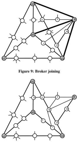
Different cases in the algorithm are illustrated below. As shown in Figure 9, B’sJoin Stellar Broker()sent via its three links may contact the brokers S0, S2 and S3 on node disjoint paths through expander nodes (r), (z, y) and (w, p) respec-tively. Nodes S0, S2 and S3 respond with paths and sug-gested brokers. Node B, on getting these messages, finds the three disjoint paths and decides to establish these links. On the other hand, suppose from all links of B, stellar nodes are not contacted through node disjoint paths. Consider Figure 10. The initial path found by theJoin Stellar Brokersare
(g, y, h)to S0,(z, y, h)to S2 and(w, p)to S3 respectively. TheNew Contactmessage from S3 contains the hint, con-tact S0 through nodel. When B contacts S0 through nodel
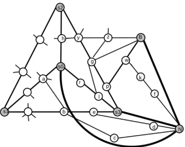
it finds the path(g, l, r)to S0. In this manner it finds three node disjoint paths to the network. If such a path had not been present, ultimately the suggestions list would become empty andMake Brokerwould terminate with a failure be-cause it is not possible to provide a connectivity of three to the broker network if B is also made a broker. Now let us consider a third case, arising when there are more broker nodes in the broker network. Figure 11 illustrates the case in which theJoin Stellar Brokermessage from an aspiring broker node N, to S2 is intercepted by a broker B on the path and subsequently the overlay link is established between the new node N and the intercepting broker B. The three disjoint
s1 s3 s2 s0 y B r p w z g h l a b c d e f k N
Figure 11: Broker joining non stellar broker
paths found are (f, k, w) to B, (c, b, a) to S0 and (d, e) to S3 respectively. The new overlay links are shown with thick lines in Figure 11. s1 s3 s2 s0 y B1 r p w z g h l a b c d e f k j m v N t B2
Figure 12: Overlay overlapping paths
The fourth case illustrated is the establishment of three node disjoint paths, to three different brokers, but the paths hav-ing nodes in a common overlay link. Consider Figure 12. The aspiring broker node N finds three node disjoint paths,
(m, j, k, w)to B1,(v, f, p)to S3 and(t, c, b, a)to S0, and is allowed to join the broker network B with three overlay links to B1, S3 and S0 respectively. The nodes are a part of the overlay link B1-B2, which maps to the physical path (w, k, f, t). But there is no smallerseparating cut, hence the new broker node will have three node disjoint paths to the broker network.
A broker that wishes to stop being a broker executes aLeave Broker(B). It still remains a part of the physical network. This message is also intercepted and replied to by the neigh-bouring broker which has B as its overlay neighbour with a
Byemessage. If this node had already ceased to be a broker theLeave Brokermessage travels up all the way to the stellar node which replies with aByemessage.
Algorithm 2Leave Broker(B)
/* this is executed by a broker B to leave a broker network.*/ 1. leaving =true
2. safe =false
3. over=false
4.while(notsafe) wait; 5. stop(Execute Broker(B))
6. send(Leave Stellar Broker(B, brokerlist)) through all the links of B.
7.while(nottimeout or not over) 8. foreach node in neighbourlist
9. ifnot receive(Bye(A, B)message then wait 10. over=true
11. Stop routing in overlay.
We can visualize the process of a new broker node trying to join the broker network as an ancient ship trying to reach land by following a star. The ship stops when it finds land. The new broker node tries to reach the stellar brokers in the sea of IP addresses in the physical network, and in the process stops its search when it finds another broker already a part of the network.
5.2.1 Maintenance of the Overlay
Every overlay node executes theExecute Broker()for over-lay maintenance.
Algorithm 3Execute Broker(B)
1.while(true) /* execute until terminated*/
2.ifreceive(Join Stellar Broker(A)andleaving==false) 3. thenintercept message
4. sendN ew Contact(B, A, path, list)
5. enqueue (B,A,path,list)
6.ifreceive(Establish Broker Link(A, B, path)
7. thensend(Conf irm Broker(A, B, path))
8. dequeue(A, B, path,list) 9. add overlay path (A,B,path); 10. if(queue is empty) safe=true
11.ifreceive(Leave Stellar Broker(A, brokerlist)
12. thenadd new overlay links to the nodes in brokerlist 13. sendByemessage(A)
14.forall brokers x in neighbourlist of B 15. send(Check P ath(B, x, nodelist1))
16. ifreceive(Check P ath(x, B, nodelist2)andnodelist26= nodelist1)
17. thenupdate path()
Broker addition was discussed in the previous section. The routine for broker addition is also executed by a node already existing in the broker network as an underlay node, on turn-ing into a broker. When theJoin Stellar Brokermessage is received by the brokers on the links from the joining bro-ker node, they respond withNew Contactand new broker links get established. If in the time interval between sending
New Contactand receiving anEstablish Broker, a new bro-ker joins on the path, then theConfirm Brokeris sent by the new broker node, and the overlay link is only to that path. When the broker gets aLeave Brokermessage meant for it-self, it replies with aBye message and establishes overlay links to the neighbour of the neighbours, which is present in
the list sent by the leaving broker. Otherwise, it ignores the message and lets it proceed further up the path to the stellar node. In the overlay network every node checks its links in-formation periodically to confirm the underlay knowledge. If new expander nodes are added in the path (say, by adding a new link to a physical node), then that knowledge is updated in the overlay node, so that further node sharing information among links can be correctly assessed. TheCheck Path(A, B, brokerlist )message does this. The receiving node compares nodelist with the path by which the message actually comes and updates it. While checking the overlay information the old broker links may be modified by the old broker nodes, and new links to the new broker are added.
5.3
Complexity Analysis
Time Complexity: As the algorithm is based on routing to the stellar node in the worst case, the maximum diameter of the network would determine the upper bound on the time for sending and receiving messages. Comparing node dis-jointedness in the obtained paths is O(number of paths2∗path length2). As the number of paths is determined by the degree, and path length by the diameter, node disjointedness can be found in O (degree * diameter)2.
Message complexity: The maximum number of messages are sent for theMake Broker()routine, as theJoin Stellar Brokermessage has to be sent by the joining broker to stel-lar brokers through all its links. The number of hops of this message is bounded by maximum diameter and the number of links is bounded by the maximum degree. Hence, the mes-sage complexity is O(degree* diameter).
6. PROOF OF CORRECTNESS
We start by giving an inductive proof for the correctness for the algorithm.
Lemma: An overlay graph B’ obtained by the sequential or interleaved executions of theMake Broker()andLeave Broker()procedures by different physical nodes and concur-rent executions of theMake Broker()andLeave Broker()
procedures by different physical nodes in a given physical network G, containing an availability latent overlay B of gree three, is an availability latent overlay of availability de-gree three, i.e., any broker node in B’ has three node disjoint paths to every other broker node in B’.
Base:The initial network formed by stellar brokers has three node disjoint paths to each other by construction as shown in Figure 5.
Inductive step:If the network of brokers and expander nodes B has three node disjoint paths between every broker, then a network of broker and expander nodes B’ obtained by the execution ofMake Broker()by a single node, or concurrent execution of Make Broker()by two different nodes, or by
Leave Broker()executed by a non stellar node by two differ-ent nodes, or concurrdiffer-entLeave Broker()executions by non stellar nodes, or the concurrent execution ofMake Broker()
and Leave Broker(), also has three node disjoint paths be-tween every two broker nodes which form a part of B’.
Proof: We prove the inductive step by considering the exe-cution of the routines.
Case 1:Execution of aM ake Broker()by a nodeb. (i) Ifbhas degree less than three or it is not connected or too far off (time-out) from B, then no change is made to B, hence B’=B.
(ii) Ifbgets at least three replies that include node disjoint paths to three different broker nodes in B,x,yandz, then it joins with those links. Suppose the paths it gets are(b,
p11, p12, ... , p1n, x),(b,p21,p22, ...,p2m, y)and (b,p31,
p32, ...,p3k,z). In each of these sequences there is a first
node which is already a part of the existing overlay. Remov-ing any one node, before this first expander node each from any two of these paths, will not disconnectbas there is a third node-disjoint path frombto B. As B already has three node disjoint paths between each of its broker nodes, the re-moval of any two of these nodes does not disconnect B either. The removal of any two nodes including those subsequent to these first nodes also does not disconnectbfrom the network as B is known to have no separating pairs, and there exists a third path frombto B which does not include these two nodes. The three expander nodes at whichbjoins B, form a separating cut for B’. Ifbitself was an expander node in B, then it is allowed to join only if it has three disjoint paths, thus ensuring it has no separation cut of size less than three.
(iii) If it does not get two disjoint replies, it uses the infor-mation given by one of the replying brokers, which contains information about other expander nodes and broker nodes to contact. Hence if the node is able to link to that expander node, and this path is node disjoint to two other paths already obtained, then also B’ satisfies the availability criteria.
(iv) If it is not possible, the nodebdoes not join, so B’=B.
Case 2: Concurrent execution of Make Broker() Suppose nodesb1andb2executeMake Broker().
(i) If one or both ofb1,b2have lesser degree or get timeout then the proof enumerated in Case 1 holds.
(ii) If nodesb1andb2get three node disjoint paths each and these are to different broker/expander nodes in B, then they can simultaneously join B, and the proof for case 1 holds.
(iii) If two nodesb1andb2select paths that are mutually dis-joint but overlap with each other’s paths, it could happen in different ways as we enumerate
1. Both join to same expander nodes/node, but with disjoint paths. Both still get node disjoint paths to each other and to the rest of the network, as they have separating cuts of size at least three. This is illustrated in Figure 13.
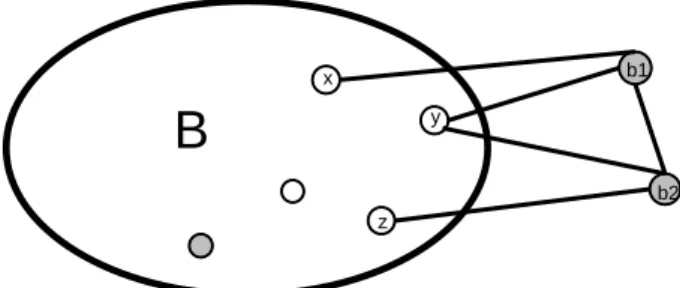
2. Both join same nodes, but with overlapping paths. This is illustrated in Figure 14.
3. One of the nodes lies in the path selected by the other as illustrated in Figure 15.
4. Both nodes lie in paths selected by each other. This is illustrated in Figure 16.
B
x y z b1 b2Figure 13: Concurrent joins with disjoint paths
B
x y z 1 2 b1 b2Figure 14: Concurrent joins with overlapping paths
B
x y z b1 b2Figure 15: Concurrent joins with single broker inclusive path
B
x y z b1 b2Figure 16: Concurrent joins with two broker inclusive paths
Case 3: Leave Broker()execution.
Leave Broker()calls, whether executed simultaneously or in-dividually, do not affect the underlying network connectivity, as it is just a change in status of the node(s) from broker to expander.
Case 4: Leave Broker()andMake Broker()execute concur-rently.
(i) If the brokers contacted byMake Broker()are different from the node executingLeave Broker()then they would each execute correctly individually as proved in cases 1 and 3.
(ii) If the broker executingLeave Broker()is one of the nodes that is contacted by the node executingMake Broker()then if the contact is made after it starts executingLeave Broker()
then theJoin Stellar messageis simply forwarded, as it would have executedleaving =true. IfLeave Brokeris executed by a broker that has already sentNew Contact, it is not allowed to proceed (by wait) until it has confirmed the path. Also, it does not send newN ew Contactmessages.
Once the leaving broker confirms the path, the other broker would put this as a neighbour and vice-versa, so while con-tinuing withLeave Broker( ), the leaving broker will wait for aByemessage from the new broker node, confirming that it has created other overlay links. Hence the algorithm ensures that B’ satisfies the required availability criterion in the pres-ence of concurrentLeave Broker()andMake Broker() exe-cutions.
7. EXPERIMENTAL FRAMEWORK
TheTrimargalgorithm has been tested on a simulated en-vironment using an event based network simulation frame-work. We have developed this simulation framework by ex-tending the Distributed System SIMulator (DSSIM) used in Hermes [1]. Our simulation framework provides for gener-ation of overlay networks of event brokers. Different event routing algorithms can be incorporated into the simulator as plugins. Thus our simulator acts as a testbed for evaluating the performance of different event routing algorithms on dif-ferent overlay topologies generated by the simulator based on the overlay formation algorithms integrated into the frame-work. There is an event driven application (a news dissemi-nation system) simulated on this environment which is used for testing the event routing algorithms on different overlay topologies.
The overlay topology formation discussed in theTrimarg al-gorithm is tested on a simulated underlying physical network generated using the Boston University Representative Inter-net Topology gEnerator(BRITE)[18]. The underlay aware overlay topology with three connectivity is generated using theTrimargalgorithm. A preliminary performance evalua-tion and scalability testing of the algorithm has been carried out. We use a BRITE generated physical network topology of 1000 nodes as the test case for the algorithm. Triconnected overlays of different sizes (10 overlay nodes to 100 overlay nodes) were generated by randomly picking up broker nodes from the physical network. The total time for creating the topology has been measured in incremental steps of 10 over-lay nodes. Also the overover-lay settling time on removal of
bro-Time for Broker Addition 0 5000 10000 15000 20000 25000 30000 35000 40000 45000 50000 20 30 40 50 60 70 80 90 100 Number of nodes T im e t a k e n t o a d d 1 0 b ro k e rs ( m s )
Figure 17: Time to add brokers
kers by execution of Leave Broker()routines has been ob-served in steps of removal of 10 randomly selected overlay nodes from the existing overlay network. The memory re-quirement at each broker node for storing the underlay path information for the incident edges (space complexity of the algorithm ) has been monitored for overlay networks of size upto 100. Our initial test results are presented in the next section. The simulations have been repeated 12 times and average values are reported here. Elaborate testing of the al-gorithm for more performance parameters, on the simulator is in progress.
8. EXPERIMENTAL RESULTS
The scalability of theTrimargalgorithm was tested by in-creasing the size of the overlay network. The number of over-lay nodes was increased from 10 nodes to 100 nodes in steps of 10 by randomly picking up broker nodes from the physical network and the results of the simulation are reported here. The values reported are the average of the values obtained for 12 simulation runs.
We report the initial test results for the experimental frame-work discussed in Section 7.
8.1 Time for overlay formation
Figure 17 depicts the simulated broker addition time as a function of number of nodes.
Discussion: Figure 17 shows that the time for broker addi-tion is independent of the size of the overlay network, prov-ing the scalability of our algorithm and its adaptability to real networks.
The time for broker deletions is measured on the simulation framework with different node sizes, starting from 100 nodes and decreased in steps of 10 to 10 nodes. The time for dele-tion of 10 broker nodes is plotted and illustrated in Figure 18.
Discussion: The graph in Figure 18 shows that the time taken for readjusting the overlay on the executions of the
Leave Broker()routine is less than that of theAdd Broker()
routine. It is due to the fact that as the underlay information is already available with the neighbouring nodes, on leaving
Time taken for deletion of broker nodes
0 20 40 60 80 100 120 100 90 80 70 60 50 40 30 20 Number of nodes T im e f o r d e le ti o n o f 1 0 b ro k e r n o d e s (m s )
Figure 18: Time to delete brokers
Average Space Requirement per broker for underlay path information 0 10 20 30 40 50 60 10 20 30 40 50 60 70 80 90 100 Number of broker nodes
A v e ra g e S p a c e R e q u ir e m e n t p e r b ro k e r (b y te s )
Figure 19: Average space for path information per broker node
of a broker, more underlay information need not be collected. The average time for readjusting the triconnected overlay is independent of the size of the overlay network emphasizing the scalability of our algorithm.
8.2 Space Requirement for underlay
in-formation
Each overlay broker node stores the underlay path informa-tion ( expander node ids) for every incident edge on it. Here we measure the average space overhead per node by measur-ing the total memory required for stormeasur-ing the underlay path information. The results of the simulation are plotted in Fig-ure 19.
Discussion: Figure 19 shows that the average memory re-quirement per broker node is constant, irrespective of the in-crease in the number of overlay nodes in the broker network. The small variations on the memory requirement is due to the random selection of the broker nodes and the random nature of the physical network used as the input.
We have tested the algorithm with different physical net-works and it has been observed that the space overhead re-mains almost the same.
9. CONCLUSIONS AND FUTURE WORK
High availability in the presence of the runtime failures is an important concern in modern distributed event based appli-cations. This paper is based on an analysis of the availability of broker networks and a study of the theoretical formula-tion of the problem of determining the availability in a broker network. This paper presents an asynchronous distributed al-gorithm for constructing and maintaining an underlay aware overlay network which ensures 3-degree of availability in the presence of node and link failures in the underlying physical network. We prove theoretically that our algorithm is cor-rect. The time complexity of our algorithm is estimated to
beO(diameter∗degree)2of the network and the message
complexity isO(diameter∗degree). The scalability of the algorithm has been tested on a simulated environment. The preliminary results of testing and evaluation of the algorithm show that the algorithm is scalable.
It was found that the broker addition time, deletion time and memory requirements for underlay information were inde-pendent of the size of the broker network. Detailed tests on the algorithm are in progress. Fault tolerant event routing al-gorithms, capable of content based event routing are being developed on this underlay aware overlay network of event brokers.
10. REFERENCES
[1] Peter R. Pietzuch. Hermes: A Scalable Event-Based Middleware. PhD thesis, Computer Laboratory, Queens’ College, University of Cambridge, February 2004. [2] Madhu Kumar S D and Umesh Bellur. An Underlay
Aware, Adaptive Overlay for Event Broker Networks. In Proceedings of the 5th International workshop on Adaptive and Reflective Middleware (ARM ’06), Mel-bourne, November 2006.
[3] Chiping Tang.Underlay-Aware Overlay Networks. PhD thesis, Michigan State University, June 2005.
[4] Madhu Kumar S D, Umesh Bellur, and V.K. Govin-dan. Adaptive Overlays for Event Based Middleware: A Case for Chordal Reliability Rings. InProceedings of the 14th International Conference on Advanced Com-puting and Communications (ADCOM 2006), IEEE press, pages 38–43, Mangalore,India, December 2006. [5] Shruti P. Mahambre, Madhu Kumar S. D., and Umesh
Bellur. A Taxonomy and Classification of Adaptive Event based Middleware with support for Service Guarantees. Technical Report IITB/KReSIT/2006/ November/36, IIT Bombay, August 2006.
[6] Andrea S Lalpaugh and Ronald L Rivest. The Subgraph Homeomorphism Problem. InProceedings of the tenth annual ACM symposium on Theory of Computing, pages 40–50, November 1978.
[7] J.E Hopcroft and R.E Tarjan. Dividing a graph into Tri-connected Components. Technical Report TR 74-197, Cornell University Ithiaca, New York, 1974.
[8] Antonio Carzaniga.Architectures for an Event Notifi-cation Service Scalable to Wide-Area Networks. PhD thesis, Politecnico di Milano, Milano, Italy, December 1998.
[9] Gianpaolo Cugola, Elisabetta Nitto, and Alfonso Fuggetta. The JEDI Event-Based Infrastructure and its Applica-tions to the Development of the OPSS WFMS.IEEE
Transactions on Software Engineering (TSE), 27(9):827– 850, September 2001.
[10] Gero Mouhl Ludger Fiege and Alejandro Buchmann. An Architectural Framework for Electronic Commerce Applications. InInformatik 2001: Annual Conference of the German Computer Society, 2001.
[11] Bill Segall and David Arnold. Elvin has left the Build-ing: A Publish/Subscribe Notification Service with Quench-ing. InProceedings of AUUG Technical Conference ’97, Brisbane, Australia, September 1997.
[12] Fengyun Cao and Jaswinder Pal Singh. MEDYM: Match-Early and Dynamic Multicast for Content-Based Publish-Subscribe Service Network. InProceedings of ICDWS, 2005.
[13] IBM TJ Watson Research Center. Gryphon: Publish/ Subscribe over Public Network.http://researchweb.watson. ibm.com/gryphon/Gryphon, 2001.
[14] Antony Rowstron and Peter Druschel. Pastry: Scalable, Decentralized Object Location and Routing for Large-Scale Peer-to-Peer Systems. InProceedings of the 3rd International Conference on Middleware, Middleware’01, pages 329–350, Heidelberg, November 2001.
[15] Guoli Li and Hans-Arno Jacobson. Composite Subscrip-tions in Content based Publish/Subscribe Systems. In
Proceedings of the Sixth International Conference on Middleware, Middleware’05, pages 249–269, Novem-ber 2005.
[16] David Anderson, Hari Balakrishnan, Frans Kaashoek, and Robert Morris. The Case for Resilient Overlay Net-works. InProceedings of Eighth Workshop on Hot Top-ics in Operating Systems,(HotOS’01), IEEE Computer Society, pages 152–157, 2001.
[17] Douglas B. West.Introduction to Graph Theory. Pren-tice Hall of India, 1999.
[18] Alberto Medina, Anukool Lakhina, Ibrahim Matta, and John Byers. Brite: An Approach to Universal Topology Generation. InProceedings of the International Work-shop on Modeling, Analysis and Simulation of Com-puter and Telecommunication Systems- MASCOTS’01, Cincinnati, Ohio, August 2001.