Science Arts & Métiers (SAM)
is an open access repository that collects the work of Arts et Métiers ParisTech
researchers and makes it freely available over the web where possible.
This is an author-deposited version published in:
http://sam.ensam.eu
Handle ID: .
http://hdl.handle.net/10985/12176
To cite this version :
A BEN RHOUMA, T AMADOU, H SIDHOM, C BRAHAM - Correlation between microstructure and
intergranular corrosion behavior of low delta-ferrite content AISI 316L aged in the range 550e700
C - Journal of Alloys and Compounds - Vol. 708, p.871-886 - 2017
Any correspondence concerning this service should be sent to the repository
Administrator :
[email protected]
Correlation between microstructure and intergranular corrosion
behavior of low delta-ferrite content AISI 316L aged in the range
550
e
700
C
A. Ben Rhouma
a, T. Amadou
a, H. Sidhom
a,*, C. Braham
baLaboratoire de Mecanique, Materiaux et Procedes (LR99ES05), Universite de Tunis, ENSIT, 5 AV Taha Hussein Montfleury, 1008 Tunis, Tunisia bLaboratoire Procedes et Ingenierie en Mecanique et Materiaux (PIMM, CNRS UMR 8006), ENSAM, 151 Bd de l'H^opital, 75013 Paris, France
Keywords:
Austenitic stainless steel AISI 316L ICG Aging Sensitization Microstructure
a b s t r a c t
The microstructure and the phase identification of austenitic stainless steel AISI 316L with lowd-ferrite content (d1%) and aged for up to 80 000 h at temperatures ranging from 550 to 700C were investigated by using an optical microscope (OM), a scanning electron microscope (SEM) and a trans-mission electron microscope (TEM). Local changes of chromium content, resulting from nucleation and growth of chromium-rich phases during aging, were quantitatively assessed by energy dispersive X-ray spectroscopy (EDX) in the scanning transmission electron microscope (STEM). The intergranular corro-sion behavior (IGC) of annealed and aged specimens was evaluated using the double loop electro-chemical potentiokinetic reactivation (DL-EPR) and completed by IGC morphologies according to the ASTM A262 practice A standard.
The results showed thatd-ferrite decomposed gradually into M23C6at 550C and decomposed totally into intermetallic phases (s,h,c, and R) and into secondary austenite (gr) at temperatures equal to or higher than 650C. Similarlyg-austenite decomposed into M23C6carbide at 550C and into intermetallic
phases such as h and s in addition to carbide, at higher temperatures. The time-temperature-sensitization diagram (TTS) was established and used to calculate the critical cooling rate (CCR) that prevents IGC sensitization. The analysis of IGC results leads to the conclusion that sensitization-desensitization is still controlled by the characteristics of chromium-depleted area surrounding austenite grain boundary regions. No significant effect of remainedd-ferrite and derived components on the corrosion behavior of AISI 316 L containing 1% ofd-ferrite.
1. Introduction
Austenitic stainless steels are usually recommended for appli-cations requiring high corrosion resistance materials. This property is due to the chromium content that is equal to or higher than 16 wt % that forms a self-healing protectivefilm on the surface. However, these materials have modest low-temperature mechanical strength and they are recurred for high temperature application such as in nuclear power plants where they are used in sea water cooling pumps and steam generators. Moreover, these materials are currently used in more severe environments such as offshore platforms[1], food, chemical industries and medical application [2e5]due to their good toughness at a large temperature range[6]
and to their resistance to pitting corrosion[4,7e9].
Despite the various attempts to enhance the corrosion resis-tance of these austenitic stainless steels [10e27], their
suscepti-bility to hot cracking during cooling from welding[18,28]and their sensitivity to IGC during isothermal heating or continuous cooling after heating through the sensitization temperature ranging from 500 to 800 C [16,20,29e33]remain unsolved. The state of the
literature knowledge indicates that the convenient and commonly used method to prevent hot cracking consists in introducing a small amount of
d
-ferrite in austenitic stainless steel[34e36]. It has beenreported that a
d
-ferrite fraction ranging from 1% to 6% is efficient to avoid hot cracking in the welded austenitic stainless steels. It also decreases the crack growth rate in SCC[34,35,37]. As for the sus-ceptibility to intergranular corrosion, it was reported that after welding, cooling at a rate above the CCR prevents the sensitization to IGC. Therefore some values of CCR, depending on the micro-structure and chemical composition, were provided[13]. Analysisof literature data provided by various methods and tests[38e45]
reveals the great influence of microstructure and chemical composition of austenitic steel on the IGC sensitivity and CCR. Ac-cording to Sidhom et al.[44], the IGC sensitization was related to chromium-depleted areas resulting from M23C6carbide
precipita-tion during aging at temperatures ranging from 550C to 750C of the fully austenitic stainless steel type AISI 316L. Moreover, it was shown that the IGC sensitization-desensitization was controlled by the chromium level and by the width of the chromium depleted area. Similarly, Yae Kina et al. [27] studied the intergranular behavior of AISI 304 with low ferrite content during aging at 650C and 750C, and showed that
d
-ferrite transformation tos
-phase does not occur for periods of up to 200 h. They attributed the sensitization phenomenon to M23C6carbides and reported that thematerial has healed after 48 h at 750C but has not healed at 650C due to the thermally active bulk chromium diffusion process. Moreover, authors indicated that
d
-ferrite remained stable during aging for periods of up to 200 h at 750C. However, Guanshun et al. [46]have shown that thed
-ferrite in Ti-modified super 304H de-composes rapidly intos
-phase, M23C6 carbides and secondaryaustenite during aging at 650C for periods of 4 he500 h. These
phases strongly influence the IGC resistance of the steel. They added that IGC sensitization at 650C of the studied material is associated basically with the
s
-phase. In addition, they also established that higher fractions ofd
-ferrite increase the IGC sensitization at 650C. Moreover, in the case of welded joints of austenitic stainless steels Garcia et al.[47]showed that the DOS of different welding zones has been correlated with the local changes in the material composition and its microstructure caused by the welding process. They showed thats
-phase, formed by the trans-formation of thed
-ferrite, contributed to the IGC sensitization of welded joints but less than the segregation phenomenon related to dendritic structure.Despite the several studies devoted to the effect of small amounts of
d
-ferrite on the IGC sensitization of austenitic stainless steel, some aspects are still unsolved:- Even though the instability of
d
-ferrite is evident, its decom-position process during heating and the associated quantitative depletion of chromium are still lacking for the comprehensive understanding of its effect on the corrosion behavior of austenitic stainless steel containingd
-ferrite.- The decomposition of
d
-ferrite has been often studied at rela-tively high temperatures such as 650 and 750C for relatively short aging periods of up to 500 h [27,46]. These conditions promote thes
-phase formation that generates less deep chro-mium depletion. Moreover, at this temperature range, the rapid bulk chromium diffusion enhances the healing process and IGC phenomena could then be concealed. Therefore, the conclusions related to the studied temperature range could not be valid for lower temperatures such as 600 and 550C and for very high aging durations due to other possibled
-ferrite decomposition mechanisms involving carbide precipitation.- The effect of
d
-ferrite transformation on the TTS diagram and the CCR has not yet been fully resolved due to the lack of a systematic study exploring a large range of sensitization temperatures.- There is no predictive tool of IGC sensitization-desensitization to make extrapolation of DOS reliable for longer aging times at lower temperatures from short aging periods at higher tem-perature results.
To provide answers to the above raised issues, the microstruc-tural evolution and the intergranular corrosion behavior of AISI 316L containing 1% of
d
-ferrite during aging for periods varying from 50 h to 80 000 h at temperatures ranging from 550 to 700C are worth investigating. The 1%d
-ferrite content has been recom-mended by the nuclear boiler manufacturer, in order to avoid hot cracking and brittle sigma phase resulting from welding of austenitic stainless steel AISI 316L. It is therefore of considerable importance to identify the decomposition of ferrite and austenite during the aging process and to quantify the associated chromium depletion in order to understand their specific effects on the intergranular corrosion behavior. Secondly, the DOS corresponding to various aging conditions has been established using an electro-chemical DL-EPR test, and correlated with the microstructural changes and with the chromium depletion area characteristics in order to deduce the IGC sensitization-desensitization criteria. Then, the TTS diagram was established and correlated with the TTP dia-gram in order to identify the role of phase decomposition on the IGC sensitization. The critical cooling rate avoiding IGC sensitiza-tion was calculated. Finally the effect ofd
-ferrite on the inter-granular corrosion behavior was discussed by superimposing TTS diagrams corresponding to stainless steels with different ferrite contents.2. Material and aging conditions
The investigated material is an austenitic stainless steel type AISI 316L with a low carbon content C¼0.023 wt%. The chemical composition of the steel is given inTable 1. The test specimens were cut from a 30 mm thick hot-rolled plate. In the as received state, the samples underwent two annealing treatments by water quenching subsequent to holding at 1070C for 1 h. Aging treatments were carried out on the annealed samples at temperatures ranging from 550 to 700C for a short duration such as 50 h as well as for a very long duration of up to 80 000 h.
3. Tests and methods
3.1. Microstructure investigation techniques
The ferrite content of austenitic stainless steel was evaluated by measurements using Feritoscope type FMP 30. Microstructure in-vestigations were carried out on the annealed and aged specimens before and after corrosion tests through using O. M, SEM and TEM. O. M and SEM examinations were conducted on samples polished usingfine silicon carbide papers (180e2000 grades) then polished
with 6
m
m water-based diamond suspension andfinally electro-chemically polished in 10% oxalic acid solution in order to reveal the microstructure. The TEM observations were performed on thin foils with 3 mm diameter thinned by electro-polishing in a glycol ethylene solution cooled to 273 K (0C). Second phases formed during aging were identified by electron diffraction patterns carriedTable 1
Chemical composition of the AISI 316L (wt. %).
Elements C S P Si Mn Ni Cr Mo Ti Nb Cu N B (ppm)
out on thin foils using an EM 430 Philips transmission electron microscope using 300 keV accelerating voltage. Their chemical composition was determined by EDX conducted on the carbon extractive replica in the STEM equipped with EDAX microanalysis hardware. Meanwhile, X-Ray microanalysis conducted on the thin foils was used to assess the evolution of chromium content of the depleted areas adjacent to
g
/g
grain boundaries and in thed
-ferrite islands during aging.3.2. Double loop electrochemical potentiokinetic reactivation tests and intergranular corrosion morphologies
The susceptibility to intergranular corrosion of the aged AISI 316L SS with low
d
-ferrite content was evaluated using the double loop electrochemical potentiokinetic reactivation (DL-EPR) tests conducted in a conventional three-electrode cell. The working electrode was the sample which is cut in the rolling direction (RD) in order to evaluate the reactivity of the surface with a represen-tatived
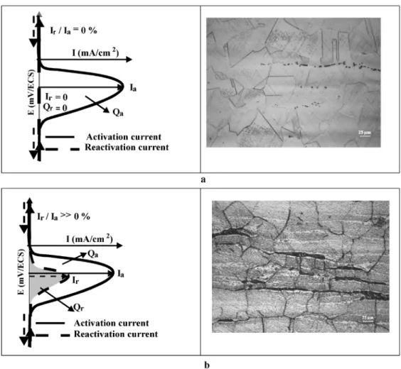
-ferrite content of the sheet (1%). The auxiliary and the reference electrodes were Pt and saturated calomel (SCE) respec-tively. Tests were carried out in an appropriate electrolyte con-sisting of 0.5 M H2SO4þ0.01 M NH4SCN at a temperature of 25C.The potential was varied from an active (- 400 mV/ECS) to a passive (þ200 mV/ECS) domain with a scan rate equal to 1 mV/s. These test conditions were previously qualified as optimal to evaluate quan-titatively the DOS of austenitic stainless steel grades[44,45]. The DOS was evaluated by the reactivation ratio (Ir/Ia%) where Ir is the reactivation (cathodic) current density peak and Ia is the activation
(anodic) current density one. A ratio equal to or higher than 1% indicates that sensitization to IGC of the tested sample is confirmed by intergranular attacks (Fig. 1). The result of DL-EPR tests were completed by IGC morphology according to ASTM A262 (practice A) [38].
4. Results
4.1. Microstructural analysis 4.1.1. Annealed microstructure
The microstructure in the annealed state consists of islands of
d
-ferrite aligned in the rolling direction of the sheet in an austenitic matrix with a grain size ranging from 70 to 100m
m. In the micro-graph, the dark phase is that of thed
-ferrite whereas the bright one is that of theg
austenite (Fig. 2a). The volume fraction ofd
-ferrite, assessed by the ferritoscope, was around 1%. The annealed micro-structure is clearly free from intergranularg
/g
andd
/g
interface precipitations as shown in TEM micrographs (Fig. 2b and c). 4.1.2. Aged microstructureSEM examinations of aged specimens reveal a rapid decompo-sition of
d
-ferrite comparatively tog
austenite during aging at temperatures ranging from 550 to 700 C. Indeed, SEM micro-graphs showed precipitates at thed
/g
interfaces while there was no visible precipitates at theg
/g
grain boundaries after aging at 550C for 1000 h (Fig. 3a). As aging at 550C continued from 1000 h to 10 000 h, precipitates grew substantially inside thed
-ferrite islandswhereas thefirst generative precipitate was observed at
g
/g
grain boundaries (Fig. 3b). After higher aging duration such as 30 000 h, the typical eutectoid microstructure was observed inside thed
-ferrite islands (Fig. 3c) and the intergranularg
/g
precipitates encountered more austenite grains (Fig. 3d). Aging at higher tem-peratures, such as 600 and 650 C, accelerates substantially the decomposition processes intod
andg
phases. Aging at 650C for 30 000 h leads to the total decomposition ofd
-ferrite (Fig. 3e) and enhances the precipitates coarsening at the boundaries and inside austenite grains (Fig. 3f). These observations imply that the higher the aging temperature, the faster the decomposition of both ferrite and austenite phases due to the involved thermally active diffusion processes.The TEM examination and the related selected area diffraction (SAD) have been used to identify the second phases formed during
aging on the basis of crystalline structure analysis. The results summarized inTable 2provide more information related to the effect of aging time and temperature on the microstructure evo-lution including precipitation sequences and sites. It can be inferred that the microstructural changes occurred easily in the
d
/g
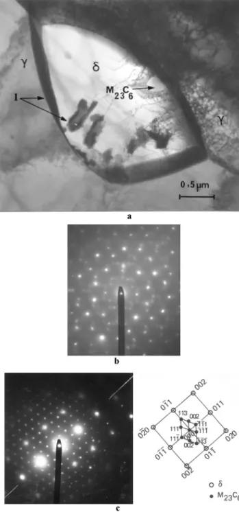
in-terfaces by the nucleation of a metastable intermetallic phase after a few hundred hours of aging at 550C (Fig. 4a and b). This phase was firstly assumed by Sidhom et al. [48] to be an icosahedral structure on the basis of typical SAD shown inFig. 4b. Whilst, Carron et al.[49]have attributed this crystalline structure to the stacking faulted Frank Kaspar phases. After 1000 h at 550C, in addition to Frank Kaspar phases, M23C6 chromium carbidesnucleated at the
d
/g
interfaces and grew intod
ferrite (Fig. 4a and c). As the aging time increased to up 10 000 h at 550C,d
-ferrite was transformed gradually into M23C6chromium carbides and into aFig. 3.Microstructure changes in austenite and ferrite during aging of AISI 316L (SEM examination): (a) Decomposition ofdferrite after aging for 1 000 h at 550C; (b) Decomposition ofdferrite after aging for 10 000 h at 550C; (c) Decomposition ofdferrite after aging for 30 000 h at 550C; d) Precipitation of chromium carbide at the austenite grain boundaries after aging for 30 000 h at 550C; (e) Total transformation ofdferrite after aging at 650C during 30 000 h; (f) Generalized precipitation in austenite after aging at 650C during 30 000 h.
Table 2
Carbides and intermetallic phases formed during aging of AISI 316L (TEM identification). T (C) Sites of Precipitation t (h) 100 1000 10 000 30 000 80 000 550 d/g F.K phase F.K phase, M23C6 M23C6 M23C6 M23C6 d F.K phase, M23C6 M23C6,gr M23C6,gr M23C6,gr g/g e e M23C6 M23C6 M23C6 g e e M23C6 M23C6 M23C6 600 d/g F.K phase, M23C6 M23C6 M23C6,h M23C6,h,s n.e d M23C6 M23C6,gr M23C6,gr M23C6,gr, n.e g/g e M23C6 M23C6,h M23C6,h n.e g e M23C6 M23C6,h M23C6,h n.e 650 d/g F.K phase, M23C6 M23C6,h d M23C6,h,s,c, R d M23C6,h,s,c, R d h,s,c, R d M23C6,gr M23C6,gr d M23C6,gr,h,,s,c, R d gr,h,s,c, R d gr,h,s,c, R g/g M23C6 M23C6,h M23C6,h,s M23C6,h,s,c h,s,c g e M23C6,h M23C6,h M23C6,h,s,c M23C6,h,s,c 700 d/g M23C6 s,gr d n.e n.e d M23C6,gr s,gr d n.e n.e g/g M23C6,h M23C6,h,s M23C6,h,s n.e n.e g M23C6 M23C6,h M23C6,h,s n.e n.e -: no precipitate. n.e: no examined. F.K: Frank Kaspar phase.
h: Laves phase.
gr: Regenered austenite.
regenerated austenite (
g
r) (Fig. 5a and b), while a small number ofcarbides appeared at the
g
/g
grain boundaries (Fig. 5c). There was no other second phase formed until 80 000 h at 550C, while the carbides coarsened substantially intod
-ferrite (Fig. 6a) at theg
/g
grain boundaries and in the dislocation pull ups into
g
grains (Fig. 6b). However, it is important to notice that, at 550C, when the aging time is extended, the Frank Kaspar phase disappears in favor of M23C6carbides and thed
-ferrite is not totally transformed afteraging for up to 80 000 h.
Aging at a higher temperature such as 650 C promotes the precipitation of various intermetallic phases in addition to M23C6
carbides. The precipitation sequences occurred firstly at the
d
/g
Fig. 4.Decomposition ofdferrite after aging at 550C during 1000 h (TEM
exami-nation): (a) F.K phase (I phase) and M23C6carbide at thed/ginterface; (b) SAD of F.K
phase anddferrite matrix; (c) SAD of M23C6carbide anddferrite matrix.
Fig. 5.Decomposition ofdferrite after aging at 550C during 10 000 h (TEM
exam-ination): (a) Decomposition ofdferrite into M23C6and regenered austenite (gr); (b)
SAD of M23C6carbide and regenered austenite (gr); (c) Nucleation of M23C6carbide at
interfaces and later at
g
/g
grain boundaries and inside the austenite grains. Therefore, thed
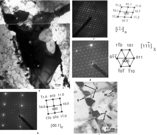
-ferrite domain gradually becomes smaller due to the decomposition process and eventually disappears completely after 10 000 h at 650C to the benefit of intermetallic phasess
,c
,h
(Laves phase), R and regenerated austeniteg
r(Fig. 7a). The SAD related to each phase was reported inFig. 7b, c, d and e. The second austenite phase
g
rformed initially at thed
/g
interfaces grew along the austenite phase edge. This phase is therefore not easily distinguishable from the annealed austenite. The
c
,h
and R phases appeared systematically with thes
-phaseFig. 6.Nucleation and growth of M23C6carbide after aging at 550C during 80 000 h: (a) Coarsing of M23C6carbide atg/dinterface; (b) Nucleation of intragranular M23C6on the
although it seems that they precipitated prior to
s
-phase because of the required higher interface energy. Moreover,s
-phase was larger than the other intermetallic phases and its volume fraction increased with increasing aging time and temperature. Otherwise, the absence of carbides, as ad
decomposition product, suggests thatthese carbides are completely dissolved in favor of
s
-phase which evolves substantially into ferrite. Because of the complete decom-position of thed
-phase, there was no significant microstructural changes related to the ferrite islands after extending the aging periods to up to 30 000 h at 650C. However, carbides,h
ands
phases nucleated at the
g
/g
grain boundaries grew by increasing aging time (Fig. 7e).The results of TEM examinations, reported inTable 2, were used to construct the TTP diagram by plotting the time and temperature of the second phase nucleation in each parent phase (
d
andg
). This diagram showed that the microstructure instability of the annealed AISI 316 L underwent decomposition during aging at temperatures ranging from 550 to 700C (Fig. 8). According to the experimental results, the transformation mechanisms of the parent phasesd
andg
that depend basically on the aging time and temperature could be described as follows:d
/(F.K) phasesþM23C6/M23C6þg
r/g
rþh
þc
þRþs
g
/g
þM23C6þh
þs
4.1.3. Chromium-rich phases
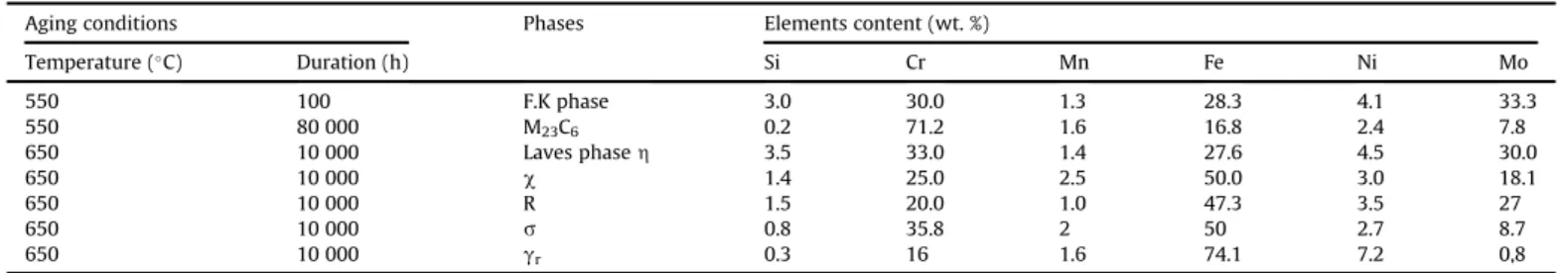
Precipitates identification was completed by quantitative anal-ysis of their chemical composition which is carried out on an extractive replica in STEM. Results reported inTable 3confirm that carbides were chromium rich phase (71 wt %). The intermetallic
Fig. 7.Precipitation of intermetallic phases after aging at 650C during 10 000 h: (a) Total decomposition ofdferrite intogr,c, R andsphases; (b) SAD ofsphase and austenite
matrix; (c) SAD of R phase; (d) SAD ofcphase and austenite matrix; (e) Nucleation and growth ofsphase at the austenite grain boundaries.
Fig. 8.TTP diagram of AISI 316 L with low ferrite content using TEM examination
compounds such as F.K,
h
,c
, R ands
were chromium and molyb-denum rich phases. These results also show that the chromium content of the secondary austenite (g
r) (14e16 wt %) resulting fromthe
d
-ferrite decomposition, is slightly lower than that of the initial austenite (17.4 wt %). The chromium enrichment of the precipitates results in the depletion of the neighboring regions, as illustrated qualitatively by chromium mapping provided by STEM X-ray image using chromium Ka
radiation (Fig. 9). Mapping showing brightness contrast is related to different Cr-enrichment. The brightest zone corresponds to Cr-enriched M23C6carbide formed during aging atthe
d
/g
interfaces (Fig. 9a) and at theg
/g
grain boundaries (Fig. 9b). It is also shown that the carbide chromium enrichment was made at the expense of the surrounding ferrite and austenite grain boundary regions.4.1.4. Chromium depleted area
As shown inFig. 9, the nucleation and growth of chromium-rich phases and mainly M23C6carbides, impact chromium content and
increase the chromium depleted zones in the vicinity of the
g
/g
grain boundaries, the
d
/g
interfaces and inside the remainedd
-ferrite. The chromium profiles, established by EDX microanalysis in STEM, provide quantitative evolution of the chromium concentra-tion and the extent of the depleted zones which are related to the intergranular (g
/g
) precipitation of chromium-rich phases which depends mainly on the aging duration and temperature (Fig. 10). It can be inferred that chromium level at theg
/g
grain boundaries (and also at theg
/M23C6interphase) falls below 12 wt % (13 at %)during aging at 550C for durations between 10 000 h and 80 000 h and that the chromium depleted area width increased from 40 nm to 200 nm (Fig. 10a). During aging at 600C, the chromium content at the
g
/g
grain boundaries falls below 12 % wt after a period of 1000 h and recovers gradually its initial level after a duration higher than 30 000 h (Fig. 10b). At a temperature of 650 C, the rechromisation phenomenon was fast enough for theg
/g
chro-mium level (16.5 wt %) to almost fully recover when the aging time reaches 10 000 h (Fig. 10c).Similarly, the
d
-ferrite chromium concentration decreased significantly during aging as a consequence of carbides and inter-metallic phase precipitation (Fig. 11). The minimum chromium content ranging from 8 wt % to 10 wt % was reached at 550C for aging durations ranging from 10 000 h to 80 000 h. At higher temperatures, chromium decreased rapidly below 8 wt % before complete decomposition ofd
-ferrite which occurred after 30 000 h at 600C, 10 000 h at 650C and only 100 h at 700C. Therefore 14 to 16 wt % chromium content was measured in sec-ondary austenite (g
r).4.2. Intergranular corrosion behavior 4.2.1. Time-temperature-sensitization diagram
The experimental values of the ratio Ir/Ia (%), resulting from the DL-EPR tests conducted on the annealed and aged specimens are
listed inTable 4. Ir/Ia, considered as an indicator of the DOS, evolved from 0% (unsensitized state) to 38.4% (very sensitized state). The sensitization at 550 C occurred after 10 000 h and continued beyond 80 000 h. At higher temperatures, the sensitization is rapid and followed by the desensitization, which is marked by the drop of the Ir/Ia ratio to 0%. This desensitization occurs after aging for
Table 3
Chemical composition of carbide and intermetallic phases formed during aging of AISI 316L (EDS analysis in STEM).
Aging conditions Phases Elements content (wt. %)
Temperature (C) Duration (h) Si Cr Mn Fe Ni Mo 550 100 F.K phase 3.0 30.0 1.3 28.3 4.1 33.3 550 80 000 M23C6 0.2 71.2 1.6 16.8 2.4 7.8 650 10 000 Laves phaseh 3.5 33.0 1.4 27.6 4.5 30.0 650 10 000 c 1.4 25.0 2.5 50.0 3.0 18.1 650 10 000 R 1.5 20.0 1.0 47.3 3.5 27 650 10 000 s 0.8 35.8 2 50 2.7 8.7 650 10 000 gr 0.3 16 1.6 74.1 7.2 0,8
Fig. 9.Chromium depleted area resulting from nucleation and growth of M23C6
rich-chromium carbide after aging at 600C during 10 000 h (STEM micrographs); (a) Ka
chromium mapping intod ferrite; (b) Ka chromium mapping of austenite grain boundarie region.
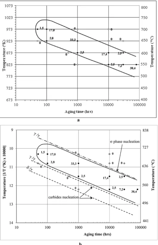
periods longer than 30 000 h at 600C, 10 000 h at 650C and 1000 h at 700C. Using the sensitization criteria Ir/Ia1%, the TTS diagram was established (Fig. 12a). It can be inferred that aging at temperatures ranging from 550 to 700C sensitized the low ferrite content austenitic stainless steel to IGC. At the peak temperature which is around 730C, the time required for sensitization is about 50 h while it is higher than 8000 h at 550 C. The sensitization period (
D
t¼tf-ts) defined as the difference between thesensiti-zation finishing time (tf) and the sensitization starting time (ts)
varies between 650 h at 700 C and 200 000 h at 550 C. It is important to notice that, in industrial practice, the TTS diagram can be directly used for controlling the risk of IGC sensitization under isothermal heating. In order to avoid the sensitization resulting from continuous cooling through the sensitization temperature range, the cooling rate must be above a critical value. This value is different from that provided by the intersection of superimposed cooling curve and the isothermal TTS diagram as
DT700 500
Dt700 500¼
220±20C=h. This difference is the result of not taking into
account the effect of time spent at the different temperature levels during cooling. Therefore, Dayal et al.[13]proposed a new method to calculate, from TTS diagram, the CCR which is of great interest to predict whether the cooling of heated or welded structure was sensitized or not. According to Dayal et al., the CCR is given by equation(1): CCR¼
D
TX TH TL 1 ts (1)Where THis the highest temperature, TLis the lowest
temper-ature, ts is the sensitization time and
D
T is the temperature dif-ference in the considered small temperature steps.The calculated CCR value is 24 K/h for AISI 316L with 1%
d
-ferrite. Otherwise, from the superimposition of TTP and TTS diagrams inselected 1/T (K)-Ln (t) axis (Fig. 12b) it can be seen that:
- The IGC sensitization is considered to be the consequence of M23C6carbide nucleation and growth, while it seems to be
in-dependent of
s
-phase precipitation which occurs at higher temperature and longer aging duration corresponding to desensitization region;- The chromium-rich carbide precipitation and subsequent sensitization and desensitization phenomena are thermally activated processes. Assuming that the processes follow an Arrhenuis rate equation, the time to IGC sensitization can be written as follows: t¼C:exp e Q RT (2) Where C is a constant, R¼8:314J:mol1:K1, Q (J:mol1) is the
activation energy and T is the absolute temperature in Kelvin. The activation energy which is valid at temperatures ranging between 550C and 700C was assessed to be 260±14KJ:mole1
corresponding to the Chromium diffusion process in austenitic steels as reported in the literature[14]. Therefore, an equivalent
timeetemperature relationship can be used to predict the duration
of equivalent DOS resulting from other aging temperatures, using the following equation:
t1 t2¼exp Q R 1 T1 1 T2 (3) Where t1is aging duration at temperature T1, t2is aging duration at
temperature T2, R is ideal gas constant and Q is apparent activation
energy.
Using this equation, it is easy to verify that the DOS of samples aged for 10 000 h at 550C is similar to that of samples aged for 1000 h at 600C.
4.2.2. Intergranular corrosion morphologies
The IGC morphologies observed after etching according to the ASTM A262 practice A standard, for various aging conditions revealed globally an attacked structure“closely”correlated with the DOS determined by the Ir/Ia ratio. It is clear that the higher the DOS the wider the corrosion attack at the
g
/g
grain bound-aries, which indicates a selective dissolution of chromium depleted area (Fig. 13). As expected, the annealed specimen which is declared unsensitized by the DL-EPR test (DOS¼0%) did not show any IGC attack and consequently, it is classified as“step structure”, according to the ASTM A262 practice A standard[38] (Fig. 13a, d and 13g). However, the specimens aged at 550 C showed evident attack at theg
/g
grain boundaries, a slight attack at thed
/g
interface and a local attack insided
. These attacks increased with increasing aging time as evidenced by the DOS evolving from 2.5% for a 10 000 h aging period (Fig. 13b) to 38.4% for an 80 000 h aging period (Fig. 13c). For 10 000 h aging period, attack structure were classified as “dual structure”, meanwhile for 80 000 h aging period the attack structure was considered as“ditch structure”since numerous grains were completely encir-cled by attack. Similar morphologies (dual) were observed at higher temperatures but for shorter aging periods such as 1000 h at 600C (Fig. 13e) and 100 h at 650C (Fig. 13h). Longer periods at these temperatures showed ditch structure (Fig. 13f and i). Based on the above observations, the DL-EPR test results are correlated with the results of tests conducted according to the ASTM A262 practice A and therefore, the criterion of sensi-tization starting Ir/Ia1% is realistic since it is well validated by the IGC morphologies shown inFig. 13. It is important to notice
Fig. 11.Evolutiondferrite chromium content during aging of AISI 316 L.
Table 4
DOS values resulting from DL-EPR tests carried out on the aged AISI 316L specimens. Aging conditions Degree of sensitization
Temperature (C) Duration (h) Ia(mA/cm2) Ir(mA/cm2) Ir/Ia(%) Qa(mC/cm2) Qr(mC/cm2) Qr/Qa(%)
1100 1 1.79 0.0 0.0 107.66 0.0 0.0 550 1000 2.29 0.0 0.0 150.15 0.0 0.0 10 000 5.25 0.13 2.5 429.22 39.15 9.1 30 000 11.06 0.8 7.2 1054.6 178.3 16.9 80 000 11.16 4.28 38.4 1093.8 550.5 50.3 600 500 2.14 0.0 0.0 135.12 0.0 0.0 1000 9.24 0.23 2.5 752.18 27.48 3.7 10 000 9.45 1.64 17.4 781.24 167.2 21.4 30 000 20.13 0.51 2.5 1990.5 50.44 2.5 650 50 2.05 0.0 0.0 131.12 0.0 0.0 100 8.83 0.24 2.8 736.76 26.22 3.6 1000 9.87 3.29 33.3 910.27 291.5 32.0 10 000 26.15 0.0 0.0 2369.2 0.0 0.0 30 000 40.04 0.0 0.0 3832.0 0.0 0.0 700 50 3.35 0.20 2.6 1391.9 43.15 3.1 100 4.54 0.77 17.0 375.75 81.89 21.79 1000 15.43 0.0 0.0 1357.7 0.0 0.0 10 000 29.62 0.0 0.0 2604.7 0.0 0.0
that the attack on the
d
/g
interface was rarely observed, even after a total decomposition ofd
-ferrite intos
-phase. This sug-gests that there is no detrimental effect of the 1% wt of thed
-ferrite on the IGC resistance of austenitic stainless steel. However some pits resulting fromd
-ferrite decomposition were observed in the vicinity ofs
-phase (Fig. 14).4.3. Microstructure-intergranular corrosion sensitization/ desensitization relationship
The correlation between microstructure and DL-EPR results completed by the IGC morphologies is evidenced by data reported inTable 5. It gives a great importance to chromium-depleted areas
which are characteristics of the corrosion behavior of low ferrite content AISI 316L stainless steel. It appears that aging at tempera-tures ranging from 550 to 700C for exposure periods varying between 100 h and 80 000 h generated various chromium-rich phases and mainly M23C6 which are responsible for chromium
depletion in the vicinity of austenite grain boundaries and inside the ferrite islands. The nucleation and growth of carbides during aging modify significantly the size and the chromium concentra-tion (% Cr) of the depleted areas as shown in column 3, 4 and 5 of Table 5. Columns 6 and 7 showed that the IGC sensitization cor-responding to DOS1% results in predominant intergranular at-tacks (ditch structure) occurring in the chromium-reduced areas with a concentration below the critical value of (% Cr)min12-13 %
wt and with a width more than 100 nm. Nevertheless, the desen-sitization, (self-healing) corresponding to a step structure, was achieved when the critical value of the chromium was recovered. The aged
d
-ferrite islands are not significantly attacked since their chromium content remained above the critical value (12e13 %wt)during aging for short periods such as 1000 h at 550C, less than 100 h at 600C and 10 h at 650C. This concentration became higher (14 %wt) after the total decomposition into chromium-rich secondary austenite (
g
r) ands
-phase which occurred for the longdurations such as 30 000 h at 600C, more than 1000 h at 650C and 100 h at 700C.
5. Discussion
The weldability improvement of austenitic stainless steels re-quires a small fraction of
d
-ferrite that could be achieved by reba-lancing the austenitic stainless steel's chemical composition combined with annealing treatment conditions. Therefore, by controlling the equivalent chromium (Creq¼23.48 wt %) and the equivalent nickel (Nieq¼14.33 wt %) contents, the annealed AISI 316L structure consists of a small fraction ofd
-ferrite dispersed in an austenite matrix. The subsequent thermo-mechanical treat-ments formed aligned islands of ferrite in the sheet's rolling di-rection. The Feritoscope FMP30 measurements provide a fraction ofd
-ferrite of about 1% which is in agreement with values deduced from the Price&Andrews diagram[50].Microstructural investigations, conducted in this study, confirmed the well-known instability of both
g
-austenite andd
-ferrite components of the annealed structure during aging at temperatures ranging from 550 to 700C[27,46]. Moreover, the fast decomposition ofd
-ferrite during aging is expected in accordanceFig. 13.ICG morphologies observed after the DL-EPR test (Optical micrographs); (a) 550C - 1000 h, DOS¼0%, step; (b) 550C - 10 000 h, DOS¼2.5%, dual; (c) 550C - 80 000 h,
DOS¼38.4%, ditch; (d) 600C - 500 h, DOS¼0%, step; (e) 600C - 1000 h, DOS¼2.5%, dual; (f) 600C - 10 000 h, DOS¼17.4%, ditch, (g) 650C - 50 h, DOS¼0%, step; (h) 650C -100 h, DOS¼2.8%, dual; (i) 650C - 1000 h, DOS¼33,3%, ditch.
with the literature results that attributed this phenomenon to the high chromium (27 wt %) and molybdenum (4 wt%) contents, compared to those of austenite which are equal to 17.3 wt % and 2.6 wt % respectively. Furthermore, the fast chromium diffusion in bcc structure of
d
-ferrite comparatively to fcc structure ofg
-austenite as reported in the literature[14]supports the TTP dia-gram results shown in Fig. 8, indicating the beginning of the chromium carbide precipitation atd
/g
interfaces during aging at temperature ranging from 550 to 700C. Therefore, thed
-ferrite decomposed gradually into chromium-rich M23C6carbide and intochromium-rich and molybdenum intermetallic phases such as F.K,
h
,s
,c
and R. The ultimate stage of decomposition tos
-phase and regenerated austeniteg
rwas achieved during aging at 650C and at700C as shown inFig. 7. Thesefindings are complemented by the quantitative data reported inTable 2. The decomposition products of the
d
-ferrite during aging have been reported in previous studies related to austenitic stainless steels with low ferrite content [27,31,34,46,51] and to duplex stainless steels [42,52]. This decomposition depends mainly on the chemical composition of the material and on aging temperature. In this study, it has been shown that the precipitation of staking faulted FK phase at thed
/g
in-terfaces was prior to that of M23C6 carbide due to the highconcentration of chromium and molybdenum in
d
-ferrite. By pro-longing the aging period, the FK phase growth reduces the ferrite domain and consequently increases the carbon activity in thed
-ferrite that enhances the M23C6 carbide nucleation as shown in Fig. 4. In its turn, the growth of carbide consumes more chromium and molybdenum that favors the dissolution of metastable FK phase in benefit of more stable M23C6carbide as shown inFigs. 5a and 6a. Thesefindings are in accordance with the author's previous work[14,48]. The involved process of carbide growth is attributed to the diffusion of carbon atoms fromg
-austenite and the diffusion of chromium and molybdenum atoms fromd
-ferrite to thed
/g
in-terfaces as reported by several authors[14]. This process created chromium and molybdenum depleted zones inside thed
-ferrite reducing its chromium concentration from 27 wt % to 7 wt % during aging for very long duration at 550 C as shown inFig. 11. The chromium-depleted zone was also generated by intergranularg
/g
carbide and chromium concentration in the vicinity of grain boundaries and which continues to decrease as the growth process of carbide continues to operate. The replenishment occurs when the chromium-consuming process is slowed sufficiently due to the decrease of the carbon activity in the austenite. The dechromisation and rechromisation phenomena were illustrated by the chromium profiles shown inFig. 10. Aging at higher temperatures accelerates the nucleation and the growth of carbides at the
g
/g
grain boundaries and at thed
/g
interface, resulting in a significant decrease of the carbon content of austenite. Therefore, the chromium-rich and molybdenum-rich intermetallic phases, such ass
,c
and R, and requiring higher energy sites as reported in previous works[14,48], precipitate at the M23C6/g
and M23C6/d
in-terfaces as shown inFig. 7a. Laves phase
h
was also observed at the M23C6/g
interface. It also exists within austenite grains throughprolonging the aging period at 650C. The growth of these phases was likely to be performed at the expense of intergranular carbides which become less apparent compared to larger plates of
s
-phase. However, the chromium depletion related to carbides is more sig-nificant than that resulting from intermetallic phases although they are also chromium-rich phases. Sahlaoui et al.[53]have demon-strated that nucleation ofs
-phase required high energy sites and a chromium level higher than 14 wt%. The correlation between microstructure and the DOS, coupled with attack morphologies as in accordance with the ASTM A262 practice A standard, revealed that the IGC sensitization-desensitization are only controlled by the level and the extent of chromium depletion resulting from the nucleation and the growth of M23C6carbide at the austenite grainFig. 14.Pits resulting fromd-ferrite decomposition observed in the vicinity ofs-phase
after aging at 650C during 10 000 h.
Table 5
Correlation between chromium depleted zones and IGC sensitization evaluated by the DOS values and IGC morphologies.
Aging conditions Depleted zones characteristics IGC Morphology
DOS (%)
Resulting from DL-EPR tests Chromium level
(wt. %)
Extend of depleted zone (nm)
Temperature (C) Duration (h) g/g d WD
Annealed state 17.4 27 0 Step 0
550 1000 17.4 17.5 e Step 0 10 000 11 8.1 42 Dual 2.5 30 000 10.5 8.8 110 Ditch 7.2 80 000 12 10 215 Ditch 38.4 600 500 13 13 e Step 0 1000 11.8 7.7 72 Dual 2.5 10 000 12.8 9 103 Ditch 17.4 30 000 13.2 14a 0 Ditch 2.5 650 100 14 10 0 Dual 2.8 1000 12.1 13.4 104 Ditch 33 10 000 16.5 16a 0 Step 0 700 100 11.8 16a e Ditch 17
boundaries. It has been established that chromium depletion in the vicinity of austenite grain boundaries, below 12e13 wt% and
extending over 100 nm in width sensitizes the AISI 316L with l % of
d
-ferrite. However, the replenishment over 12e13 wt% ofchro-mium leads to self-healing. Otherwise, the contribution of
d
-ferrite to IGC sensitization seems to be not effective or negligible. This result corroborates Guanshun et al.’s one[46], indicating that the DOS of Ti modified Super 304H is still insignificant during aging at 650 C for ad
-ferrite content below 3.9%. Increasing the ferrite fraction to 6.1% strongly deteriorates the IGC resistance at the same aging conditions. Authors attributed this result to the small contribution to IGC sensitization of the limited depleted areas related to low fraction ofd
-ferrite. This tendency is clearly evi-denced byFig. 15, showing the superimposition of TTS curves cor-responding to 0%[44] 1% (this study) and 45%[42] ofd
-ferrite. Concerning this study, the correlation between microstructure and the DOS values provides more explanation. Indeed, after aging at 550C for relatively short period of up to 1000 h, the dechrom-isation intod
-ferrite was not enough (Cr13 wt %) to provoke IGC, and therefore, the DOS remained less than 1%. By prolonging aging at the same temperature to up to 10 000 h, the DOS was higher than 2% and the“ditch” structure was related to chromium-depleted austenitic grain boundaries as shown inFig. 13. This means that the contribution of the low fraction of chromium-depleted areas related tod
-ferrite and to DL-EPR response is negligible compared to that of the austenite grain boundaries areas. At higher temper-atures, thed
-ferrite totally disappears with the associated depleted zones, since the chromium content of the regenerated austeniteg
r(Cr %¼16) is approximately equal to that of the initial
g
-austenite (Cr % ¼ 17.4). Therefore, the IGC sensitization is exclusively controlled by the chromium-depleted zones related to austenitic structure. That is why the TTS diagram of fully austenitic stainless steel completely coincides with that of low ferrite content austenitic stainless steel at very long aging durations, as shown in Fig. 15. In addition, chromium carbide (M23C6)and the associatedchromium-depleted zones near the
g
/g
grain boundaries are considered as the main element responsible for IGC sensitization of AISI 316L with 1%d
-ferrite sinces
-phase appears at aging durations longer than 10 000 h at temperatures higher than 650C. These last parameters correspond to the occurrence of the rechromisation process which is in accordance with previous modeling and experimental work devoted to fully austenitic stainless steels[54]. Using TTS diagrams and equation(1) [13], the CCR to prevent IGC sensitization of AISI 316L with 1%d
-ferrite (24 K/h) has beendetermined and compared to that of AISI 316L fully austenitic stainless steel (86 K/h). The lower value of CCR corresponding to AISI 316L with 1%
d
-ferrite is rather assigned as a beneficial effect of higher nitrogen level (N¼0.08 %wt) when compared to that of AISI 316L (N¼0.035 %wt), as reported by previous works[11e13].6. Conclusion
Aging at temperatures ranging between 550 and 700 C for periods varying from 50 h to 80 000 h modifies the microstructure and the IGC behavior of austenitic stainless steel AISI 316L with 1%
d
-ferrite. The microstructural changes occur faster in ferrite than in austenite. The TTP diagram, constructed on the basis of TEM ex-amination, outlines that precipitation processes are thermally active and controlled by chromium diffusion mechanism. The precipitation of chromium-rich and molybdenum-rich phases such as M23C6carbide FK,h
,s
,c
and R, generates a chromium-depletedarea in ferrite and in the vicinity of austenite grain boundaries. However, the corrosion behavior of aged steel, assessed by DL-EPR tests, is only affected by the
g
/g
M23C6carbide precipitation and theassociated chromium depletion zones. IGC sensitization occurred, in the conditions of this study, for DOS1% when the chromium concentration falls below the critical value of 13 wt % and a width of the depleted zone higher than 100 nm. The self-healing is achieved when the critical value of chromium is recovered. The low ferrite content, recommended for hot cracking resistance and its decom-position products such as
s
,c
and R during aging, does not alter the steel corrosion behavior since the TTS diagram remained coinci-dent with that of fully austenitic stainless steel. The CCR preventing any risk of IGC sensitization, and calculated from the TTS diagram and using Dayal method, is found to be 24 K/h.References
[1] M. Cindra Fonseca, I.N. Bastos, E. Baggio-Saitovitch, D.R. Sanchez, Character-ization of oxides of stainless steel UNS S30400 formed in offshore environ-ment, Corros. Sci. 55 (2012) 34e39.
[2] C. Jullien, T. Benezech, B. Carpentier, V. Lebret, C. Faille, Identification of sur-face characteristics relevant to the hygienic status of stainless steel for the food industry, J. Food Eng. 56 (2003) 77e87.
[3] Y. Ke, R. Yibin, Nickel-free austenitic stainless steels for medical applications, Sci. Technol. Adv. Mater. 11 (2010) 014105.
[4] M. Talha, C.K. Behera, O.P. Sinha, A review on nickel-free nitrogen containing austenitic stainless steels for biomedical applications, Mater. Sci. Eng. C 33 (2013) 3563e3575.
[5] E. Mohammadi Zahrani, A. Saatchi, A. Alfantazi, Pitting of 316L stainless steel inflare piping of a petrochemical plant, Eng. Fail. Anal. 17 (2010) 810e817.
[6] M. Milititsky, D.K. Matlock, A. Regully, N. Dewispelaere, J. Penning, H. Hanninen, Impact toughness properties of nickel-free austenitic stainless steels, Mater. Sci. Eng. A 496 (2008) 189e199.
[7] H. Sidhom, A. Ben Rhouma, C. Braham, J. Ledion, Preparation des surfaces et tenuea la corrosion localisee des aciers inoxydables austenitiques, Mat er. Tech. 86 (N9e10) (1998) 31e37.
[8] A.B. Rhouma, H. Sidhom, C. Braham, J. Ledion, M.E. Fitzpatrick, Effects of surface preparation on pitting resistance, residual stress, and stress corrosion cracking in austenitic stainless steels, J. Mater. Eng. Perform. 10 (2001) 507e514.
[9] G. Bai, S. Lu, D. Li, Y. Li, Influences of niobium and solution treatment tem-perature on pitting corrosion behaviour of stabilised austenitic stainless steels, Corros. Sci. 108 (2016) 111e124.
[10] B. Kartik, R. Veerababu, M. Sundararaman, D.V.V. Satyanarayana, Effect of high temperature ageing on microstructure and mechanical properties of a nickel-free high nitrogen austenitic stainless steel, Mater. Sci. Eng. A 642 (2015) 288e296.
[11] Y.J. Oh, J.H. Hong, Nitrogen effect on precipitation and sensitization in cold-worked Type 316L(N) stainless steels, J. Nucl. Mater. 278 (2000) 242e250.
[12] R. Beneke, R.F. Sandenbergh, The influence of nitrogen and molybdenum on the sensitization properties of low-carbon austenitic stainless steels, Corros. Sci. 29 (1989) 543e555.
[13] N. Parvathavarthini, R.K. Dayal, Timeetemperature-sensitization diagrams and critical cooling rates of different nitrogen containing austenitic stainless steels, J. Nucl. Mater. 399 (2010) 62e67.
[14] H. Sidhom, Etude de l’evolution structural au cours du vieillissement de deux
aciers inoxydables austenitiques, et de son influence sur les proprietes
Fig. 15.Effect of ferrite content on the IGC sensitization of stainless steel derived from
mecaniques et la corrosion inter-cristalline, University of Paris XI, Paris, 1990. [15] A. Pardo, M.C. Merino, A.E. Coy, F. Viejo, M. Carboneras, R. Arrabal, Influence of Ti, C and N concentration on the intergranular corrosion behaviour of AISI 316Ti and 321 stainless steels, Acta Mater. 55 (2007) 2239e2251.
[16] K. Chandra, V. Kain, R. Tewari, Microstructural and electrochemical charac-terisation of heat-treated 347 stainless steel with different phases, Corros. Sci. 67 (2013) 118e129.
[17] H.S.I. Trigui, C. Braham, J. Ledion, La corrosion par piqûres d'aciers inoxydables austeno-ferritiques dans l'eau de mer synthetique - influence de la compo-sition chimique et de la teneur inclusionnaire, materiaux et techniques, Hors seris, 1996, pp. 23e30.
[18] J. Verma, R.V. Taiwade, Dissimilar welding behavior of 22% Cr series stainless steel with 316L and its corrosion resistance in modified aggressive environ-ment, J. Manuf. Process. 24 (Part 1) (2016) 1e10.
[19] M. Zie˛tala, T. Durejko, M. Polanski, I. Kunce, T. Płocinski, W. Zielinski, M. Łazinska, W. Ste˛pniowski, T. Czujko, K.J. Kurzydłowski, Z. Bojar, The microstructure, mechanical properties and corrosion resistance of 316 L stainless steel fabricated using laser engineered net shaping, Mater. Sci. Eng. A 677 (2016) 1e10.
[20] Y. Cai, Z. Luo, M. Feng, Z. Liu, Z. Huang, Y. Zeng, Effect of activator on me-chanical properties and intercrystalline corrosion resistance of austenitic stainless steel weld, J. Mater. Process. Technol. 234 (2016) 243e248.
[21] C. Garcia, F. Martin, P. de Tiedra, Y. Blanco, M. Lopez, Pitting corrosion of welded joints of austenitic stainless steels studied by using an electrochemical minicell, Corros. Sci. 50 (2008) 1184e1194.
[22] M. Dadfar, M.H. Fathi, F. Karimzadeh, M.R. Dadfar, A. Saatchi, Effect of TIG welding on corrosion behavior of 316L stainless steel, Mater. Lett. 61 (2007) 2343e2346.
[23] C. Braham, A. Ben Rhouma, J. Ledion, H. Sidhom, Effect of machining condi-tions on residual stress corrosion cracking of 316L SS, Mater. Sci. Forum 490e491 (2005) 305e310.
[24] J.B. Cai, C. Yu, R.K. Shiue, L.W. Tsay, Stress corrosion cracking of austenitic weld deposits in a salt spray environment, J. Nucl. Mater. 465 (2015) 774e783.
[25] K.N. Lyon, T.J. Marrow, S.B. Lyon, Influence of milling on the development of stress corrosion cracks in austenitic stainless steel, J. Mater. Process. Technol. 218 (2015) 32e37.
[26] J.Z. Lu, K.Y. Luo, D.K. Yang, X.N. Cheng, J.L. Hu, F.Z. Dai, H. Qi, L. Zhang, J.S. Zhong, Q.W. Wang, Y.K. Zhang, Effects of laser peening on stress corrosion cracking (SCC) of ANSI 304 austenitic stainless steel, Corros. Sci. 60 (2012) 145e152.
[27] A.Y. Kina, V.M. Souza, S.S.M. Tavares, J.M. Pardal, J.A. Souza, Microstructure and intergranular corrosion resistance evaluation of AISI 304 steel for high temperature service, Mater. Charact. 59 (2008) 651e655.
[28] A. Abou-Elazm, R. Abdel-Karim, I. Elmahallawi, R. Rashad, Correlation be-tween the degree of sensitization and stress corrosion cracking susceptibility of type 304H stainless steel, Corros. Sci. 51 (2009) 203e208.
[29] M. Matula, L. Hyspecka, M. Svoboda, V. Vodarek, C. Dagbert, J. Galland, Z. Stonawska, L. Tuma, Intergranular corrosion of AISI 316L steel, Mater. Charact. 46 (2001) 203e210.
[30] M. Terada, D.M. Escriba, I. Costa, E. Materna-Morris, A.F. Padilha, Investigation on the intergranular corrosion resistance of the AISI 316L(N) stainless steel after long time creep testing at 600C, Mater. Charact. 59 (2008) 663
e668.
[31] N. Yoshikuni, N. Kazutoshi, I. Mitsunori, Influence of delta-ferrite on sensiti-zation of the austenitic stainless steel weld metal, Q. J. Jpn. Weld. Soc. 9 (1991) 415e422.
[32] F. Wilson, Mechanism of intergranular corrosion of austenitic stainless steelsdliterature review, Br. Corros. J. 6 (1971) 100e108.
[33] J.J. Heger, J.L. Hamilton, Effect of minor constituents on the intergranular corrosion of austenitic stainless steels, Corrosion 11 (1) (1955) 22e26.
[34] T. Ogawa, E. Tsunetomi, Hot cracking susceptibility of austenitic stainless steels, Weld. Res. Suppl. 61 (1982) 82se93s.
[35] J.C. Lippold, W.F. Savage, Characterization of weld solidification cracking in a duplex stainless steel weldments: Part IIIdthe effect of solidification behavior on hot cracking susceptibility, Weld. Res. Suppl. 61 (1982) 88Se96S.
[36] P. Manning, D. Duquette, W. Savage, Technical Note: the effect of retained ferrite on localized corrosion in duplex 304L stainless steel, Weld. J. (1980) 260e262.
[37] C.L. Lai, L.W. Tsay, W. Kai, C. Chen, The effects of cold rolling and sensitisation on hydrogen embrittlement of AISI 304L welds, Corros. Sci. 52 (2010) 1187e1193.
[38] ASTM A262-10, Standard Practices for Detecting Susceptibility to Intergran-ular Attack in Austenitic Stainless Steels, New York, 2010.
[39] Report No. NF EN ISO 3651e2, AFNOR, Cedex, France, 1998.
[40] Report No. NF EN ISO 3651e1, AFNOR, Cedex, France, 1998.
[41] ASTM A262e02a (Reapproved 2008), Standard Practices for Detecting Sus-ceptibility to Intergranular Attack in Austenitic Stainless Steels, ASTM, PA, 2008.
[42] T. Amadou, H. Sidhom, C. Braham, Double loop electrochemical potentioki-netic reactivation test optimization in checking of duplex stainless steel intergranular corrosion susceptibility, Metall. Mater. Trans. A 35 (2004) 3499e3513.
[43] H. Sidhom, T. Amadou, C. Braham, Evaluation by the double loop electro-chemical potentiokinetic reactivation test of aged ferritic stainless steel intergranular corrosion susceptibility, Metall. Mater. Trans. A 41 (2010) 3136e3150.
[44] H. Sidhom, T. Amadou, H. Sahlaoui, C. Braham, Quantitative evaluation of Aged AISI 316L stainless steel sensitization to intergranular corrosion: com-parison between microstructural electrochemical and analytical methods, Metall. Mater. Trans. A 38 (2007) 1269e1280.
[45] G.H. Aydogdu, M.K. Aydinol, Determination of susceptibility to intergranular corrosion and electrochemical reactivation behaviour of AISI 316L type stainless steel, Corros. Sci. 48 (2006) 3565e3583.
[46] G. Bai, S. Lu, D. Li, Y. Li, Intergranular corrosion behavior associated with delta-ferrite transformation of Ti-modified Super304H austenitic stainless steel, Corros. Sci. 90 (2015) 347e358.
[47] C. Garcia, M.P. de Tiedra, Y. Blanco, O. Martin, F. Martin, Intergranular corro-sion of welded joints of austenitic stainless steels studied by using an elec-trochemical minicell, Corros. Sci. 50 (2008) 2390e2397.
[48] H. Sidhom, R. Portier, An icosahedral phase in annealed austenitic stainless steel? Philos. Mag. Lett. 59 (1989) 131e139.
[49] D. Carron, P. Chemelle, D. Michel, M.J. Hytch, R. Portier, Icosahedral related precipitation at a nanometric scale in a superferritic steel, J. Non Cryst. Solids 153e154 (1993) 473e477.
[50] K.W.A.L. Pryce, Practical estimation of composition balance and ferrite content in stainless steels, Iron Steel Inst. 195 (1960) 415e417.
[51] W. Jolly, C. Toffolon-Masclet, J.M. Joubert, B. Marini, F. Porcher, G. Andre, F. Cortial, P. Petit, S. Ringeval, In situ monitoring of isothermal phase trans-formation in two Nb stabilized austenitic stainless steels (316Nb) by neutron diffraction, J. Alloys Compd. 688 (Part B) (2016) 695e702.
[52] S.-M. Yang, Y.-C. Chen, C.-H. Chen, W.-P. Huang, D.-Y. Lin, Microstructural characterization ofd/g/s/g2/cphases in silver-doped 2205 duplex stainless steel under 800C aging, J. Alloys Compd. 633 (2015) 48
e53.
[53] H. Sahlaoui, H. Sidhom, Experimental investigation and analytical prediction ofs-phase precipitation in AISI 316L austenitic stainless steel, Metall. Mater. Trans. A 44 (2013) 3077e3083.
[54] H. Sahlaoui, K. Makhlouf, H. Sidhom, J. Philibert, Effects of ageing conditions on the precipitates evolution, chromium depletion and intergranular corro-sion susceptibility of AISI 316L: experimental and modeling results, Mater. Sci. Eng. A 372 (2004) 98e108.