w w w . j m r t . c o m . b r
Original article
Effect of microstructure and texture on forming limits in
friction stir processed AZ31B Mg alloy
Ganta Venkateswarlu
a,∗, Ashok Kumar Singh
b, Joseph Davidson
a,
Gogineni Ravindranath Tagore
aaDepartment of Mechanical Engineering, National Institute of Technology, Warangal, AP, India bMaterials Science Division, Defence Metallurgical Research Laboratory, Hyderabad, AP, India
a r t i c l e
i n f o
Article history:
Received 20 November 2012 Accepted 31 January 2013 Available online 15 June 2013
Keywords:
Friction stir processing Texture
Forming limits
a b s t r a c t
The present work describes the influence of the friction stir processing (FSP) process param-eters, namely the tool rotational speed, the tool traverse speed, and the tool tilt angle on the forming-limit strains, the microstructure and the texture of friction stir processed magne-sium AZ31B alloy. Limiting dome height tests were carried out at different combinations of process conditions to investigate the forming behavior of FSPed material. It has been found that few combinations of the FSP parameters have resulted in homogeneous microstruc-ture. This has resulted in the larger fracture major strains than that of the base material. An attempt has been made to explain the forming limits of the material with the help of the change in the microstructure and the texture during FSP.
© 2013 Brazilian Metallurgical, Materials and Mining Association. Published by Elsevier Editora Ltda.
1.
Introduction
In recent years, magnesium alloys have been the subject of numerous research projects throughout the world because of its increased usage in the automotive and aerospace industries. Magnesium can significantly reduce the overall weight of the vehicle resulting in improved fuel economy [1–3]. However, the magnesium materials have poor forma-bility at room temperature due to limited active slip systems. The basal slip and twinning of the hexagonal closed struc-tures (hcp) are the active mechanisms for improving room temperature formability of Mg materials. The poor room tem-perature ductility of magnesium alloy has hindered the usage
∗ Corresponding author.
E-mail:ganta [email protected](G. Venkateswarlu).
of wrought magnesium alloys in automobile industries. Dif-ferent researchers have suggested difDif-ferent grain refinement techniques as a possible solution to improve the formabil-ity[4–8]. Recently, friction stir processing has been developed as one such technique for the microstructure modification [9–12], which provides an intense plastic deformation as well as higher strain rates than others.
The concept of forming limit diagram (FLD)[13]has been developed for evaluating and predicting the formability of sheet metal. The FLD is a representation of plane strain got through the combinations of the two principal surface strains, namely the major strain and the minor strain taken at dif-ferent locations of the samples that simulate the drawing conditions on the left, plane strain loading in the center, and
2238-7854 © 2013 Brazilian Metallurgical, Materials and Mining Association. Published by Elsevier Editora Ltda. http://dx.doi.org/10.1016/j.jmrt.2013.01.003
Este é um artigo Open Access sob a licença de CC BY-NC-ND
Fig. 1 – Friction stir processing.
the biaxial stretching on the right. In this study, the FLDs of the friction stir processed material are obtained at different processing conditions and they are compared with the base material. The improvement in formability has been explained based on the improvement in microstructure and texture of the FSPed materials.
Table 1 – Combination of FSPed process parameters. Sample No. Rotational
speed (RPM) Traverse speed (mm/min) Tool Tilt angle (◦) 1 900 24 0 2 900 32 1 3 900 40 2 4 1150 24 1 5 1150 32 2 6 1150 40 0 7 1400 24 2 8 1400 32 0 9 1400 40 1
2.
Experimental methodology
2.1. Friction stir processingThe 4 mm thick Mg AZ31B alloy sheet has been selected as the base metal, with the composition of (in wt.%): Al, 3.02; Zn, 0.89; Mn, 0.29; Si, 0.026; Ni, 0.0009; Fe, 0.0025; Mg-balance.
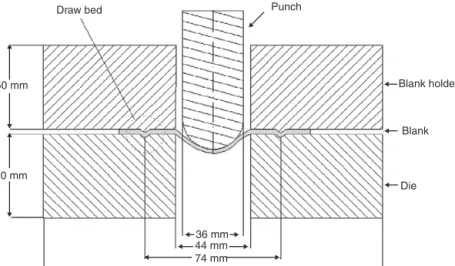
Draw bed Punch
Blank holder Blank Die 36 mm 50 mm 50 mm 74 mm 200 mm 44 mm
Fig. 2 – Schematic diagram of LDH test.
–0.2 –0.1 0.05 0.25 900-24-1 900-24-0 900-40-2 1150-24-1 1150-32-0 1150-40-0 1400-24-2 140-32-0 1400-40-1 0.15 0.15 0.05 0.05 0 0 –0.2 –0.1 0.1 0.2 –0.4 –0.3 –0.2 0.1 0 –0.1 0.2 –0.4 –0.2 0 0 0.2 –0.4 –0.2 0 0.2 0.4 0 0 –0.4 –0.2 0.2 0.4 –0.4 –0.2 0 0.2 0.4 0 –0.4 –0.2 0.2 0 –0.2 –0.1 0.1 0.2 0.3 0.1 0.1 0.2 0.25 0.15 0.05 0 0.1 0.2 0.2 0.05 0.1 0.15 0 0.2 0.05 0.1 0.15 0.2 0.2 0.1 0.05 0.15 0.25 0 0.2 0.1 0.05 0.15 0.25 0 0.2 0.1 0.05 0.15 0.25 0 0.2 0.1 0.05 0.15 0.1 0.2 0.1 0 –0.2 –0.1 0 0.1 0.2 0 Base metal Minor strain Major str ain Major str ain Major str ain Major str ain Major str ain Major str ain Major str ain Major str ain Major str ain Major str ain Minor strain Minor strain Minor strain Minor strain Minor strain Minor strain Minor strain Minor strain Minor strain
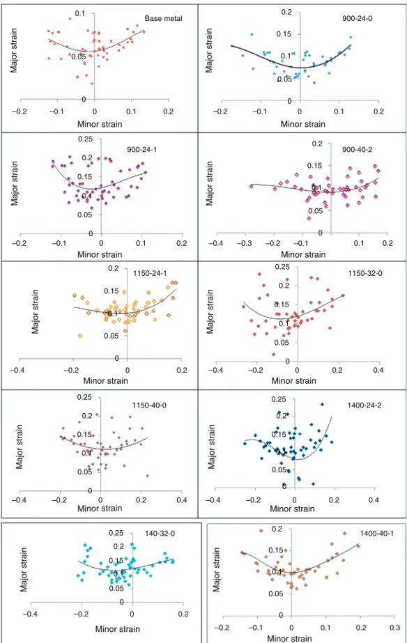
Fig. 4 – Formability diagrams.
Trial runs were done to determine the working limits of the FSP parameters. Based on the trial experimental results, the range of the process parameters such as the rotational speed was selected as 900–1400 rpm, the traverse speed was selected
as 24–40 mm/min and the tool angle was selected as 0–2◦. The friction stir processing was done on a (300 mm×150 mm) sheet using a vertical head milling machine with the posi-tion of the tool fixed relative to the surface of the sheet as
Levels Td Max:33.5 RD 32.0 20.0 10.0 6.0 4.0 2.0 00.2 100 µm
Fig. 5 – Microstructure and pole figure of base material.
shown inFig. 1. The work piece was firmly clamped to the bed and a specially made tool was plunged into the selected area of the material sheet for sufficient time in order to plas-ticize around the pin. After adequate plasticization, the tool was traversed across the surface of the material for a single pass. The entire sheet was processed with overlapped passes. A nonconsumable taper threaded tool made of high carbon steel, H13 with a shoulder diameter of 18 mm, pin diame-ter of 6 mm, and a pin length of 3 mm was used. The FSP experiments were conducted on the sheet in the rolling direc-tion as per the selected orthogonal array and are shown in Table 1.
2.2. Formability diagram
The evaluation of FLD involves three important steps, namely the grid marking the sheet specimens, forming (punch stretch-ing) using a standard punch and die in a hydraulic press and the measurement of major and minor stains. The grid mark-ing on the sheets was carried out by the chemical etchmark-ing method. The friction stir processed sheets were subjected to different states of strain modes, namely the tension–tension, plane strain and tension–compression by varying the width of the blanks. The size of the specimens was varied from an ini-tial square of 100 mm×100 mm to 100 mm×wmm (wherew, the width of the sample is taken as 10 mm, 20 mm, 40 mm, 60 mm and 80 mm) and marked with 2.5 mm circular grids using the chemical etching method to obtain the FLD of the sheet metal. Circular lock beds were provided on the dies, to restrict the flow of material from the flange region to the die. All LDH tests were carried out in dry condition at a punch speed of 0.3 mm/s on a 50 ton hydraulic press with a standard die set as shown inFig. 2 [14]. An optimum blank holding force in the range of 3–4 tons was applied. The punch was stopped immediately after the initiation of fracture was found on the specimen. The minor and major diameters of the deformed circles (ellipses) in safe, necked and fractured regions were measured by a tool maker’s microscope. The photographs of the samples (after forming) are shown inFig. 3. The major strain [e1= (major diameter of the ellipse−original diameter of the grid circle/original diameter of the grid circle)] and minor strain [e2= (minor diameter of the ellipse−diameter of the grid circle/original diameter of the grid circle)] were determined.
The major true strain and minor true strain were plotted against each other.
2.3. Microstructure and texture
Samples of size 10 mm×8 mm were cut from the FSPed
specimens for optical metallography in order to study the influence of microstructural modification on the fracture lim-its. The samples were prepared as per the standard technique used for Mg and its alloys and etched with a mixture of 4.2 g picric acid, 10 mL acetic acid, 70 mL ethanol and 10 mL diluted water solution for ∼10 s at room temperature. The texture was measured on the polished friction stirred the processed surface. An Inel G3000 texture goniometer coupled with a curved position sensitive detector using Cu K␣radiation was employed in the Schultz reflection technique[15]. Six incom-plete ({0 0 0 2},{1 0 ¯1 0},{1 0 ¯2 0},{1 0 ¯1 1},{1 0 ¯1 2}and
1 0 ¯1 3) pole figures of the hcp phase were measured from the processed surface. An oscillation stage was employed with 20 mm specimen translation to increase the measured area. From the pole figure data, the complete orientation distribu-tion funcdistribu-tion (ODF) has been calculated by triclinic sample symmetry[16].3.
Results and discussion
The formability limit diagrams of the Mg AZ31B sheets of the base material and FSP processed samples done with differ-ent process parameters combination are shown inFig. 4. This shows that the forming limit increases in all the processed samples than that of the base material. The sample 8 exhibits maximum forming limit followed by the samples 5, 4 and 6. The microstructures and texture of the base metal and the FSPed samples are shown inFigs. 5 and 6, respectively. The as received Mg alloy sheet shows coarse grain microstructure with an average grain size of 16.5m. This specimen displays strong c-type texture where the poles are located at the center of{0 0 0 2}the pole figure. The microstructures of the friction stir processed samples exhibit good grain refinement due to dynamic recrystallization. As a result, forming limits of the processed material has improved. The average grain size of the base material sample is 16.5m, and it has decreased to 9.5m
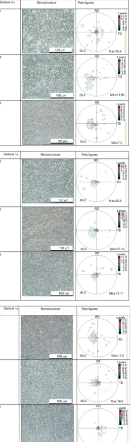
14.0 10.0 6.0 4.5 3.0 2.2 Levels Max:15.6 Max:7.6 Max:22.9 Max:37.13 Max:18.11 Max:11.5 Max:10.6 Max:51.47 Max:11.96 7.3 6.5 5.0 4.0 3.0 1.9 Levels Pole figures Microstructure Sample no. Pole figures Microstructure Sample no. Pole figures Microstructure Sample no. 22.0 17.0 12.0 8.0 5.0 2.0 Levels 35.7 25.0 14.0 8.0 4.0 2.0 Levels 17.0 14.0 10.0 7.0 4.0 2.0 Levels 11.0 9.0 7.0 5.0 3.0 1.7 Levels 11.0 8.0 6.0 5.0 3.0 1.8 Levels 48.0 35.0 20.0 10.0 5.0 2.0 Levels 11.6 00.2 00.2 00.2 00.2 00.2 00.2 00.2 00.2 00.2 9.5 7.0 5.5 3.0 2.0 Levels 100 µm 100 µm 100 µm 100 µm 100 µm 100 µm 100 µm 100 µm 100 µm RD RD RD RD RD RD RD RD TD TD TD TD TD TD TD TD TD RD 1 2 3 4 5 6 7 8 9
Fig. 6 – Microstructures and texture of FSPed specimens.
for sample 1, 6.2m for sample 2, 7.5m for sample 3, 5.4m for sample 4, 6.5m for sample 5, 5.1m for sample 6, 7.9m for sample 7, 5.8m for sample 8 and 6.1m for sample 9. The microstructure of the specimen 1 exhibits similar trend to that of the base material with only little grain refinement. The microstructure of this sample was found to be inhomogeneous with a mixture of coarse and fine grains. The texture of this specimen is similar to that of the base material although the overall intensity of the texture has reduced by nearly half. This shows that rotational speed and traverse speed has marginally refined the grain. This has been attributed to the insufficient heat generation and forging force. As a result, the specimen exhibits only slightly higher forming limit than the base mate-rial. The increase in traverse speed and tilt angle has resulted in the refined microstructure (specimen 2). The extent of inhomogeneity has reduced in comparison to that of the spec-imen 1. The poles in the basal pole figure have shifted nearly 35◦ away from the center of{0 0 0 2}pole figure and overall intensity has reduced to nearly 1/3 of the as received material. The forming limit of this specimen is better than that of speci-men 1 due to homogeneous microstructure and weak texture. Further increase in traverse speed and tilt angle (40 mm/min, 2◦) has produced coarse and inhomogeneous microstructure (specimen 3). It has significantly weakened the texture of the as received material and also shifted the basal component away from the center. The coarse microstructure in this spec-imen can be due to the insufficient heat generation during the processing. As a result, this specimen exhibited lower formability than the specimen 2 but higher than the base material.
Further increase in rotational speed from 900 to 1150 rpm has produced fine grained microstructure due to the increase in the frictional heat during processing. The specimens 4, 5 and 6 exhibit fine and homogeneous microstructure. The nature of the texture of these specimens is also similar with only a little variation in the location of the basal component in the {0 0 0 2} pole figure. The overall intensity of the tex-ture is maximum for the specimen 5. There is only marginal difference in the forming limit of these specimens. Form-ing limit of specimen 5 is higher than the other specimens. All the above three specimens showed much higher form-ing limits than those of the base metal and also higher than the specimens 1, 2 and 3. Better forming limit of these specimens can be attributed to the combined effect of uni-form microstructure and reasonably strong basal texture. Further increase in rotational speed (1400 rpm) with lowest traverse speed (24 mm/min) and highest tilt (2◦) angle has again produced inhomogeneous and coarse microstructure (specimen 7). It is known that a combination of high ratio-nal speed and lower traverse speed introduces high heat. As a result, the temperature of the specimen increases sig-nificantly and it recrystallises the deformed grains. It also introduces secondary recrystallisation due to high temper-ature. The overall intensity of the texture of this specimen has reduced to 1/3 times of the as received material and location of the basal pole has shifted nearly 30◦ away from the center in the {0 0 0 2} pole figure. This specimen exhibits lower forming limit than those of the specimen 4, 5 and 6 and higher forming limit than the as received material.
The increase in traverse speed and tilt angle at higher rota-tional speed has produced uniform microstructure (specimen 8) that that of the specimen 7. The overall intensity of the texture of the specimen is nearly same as that of the sam-ple 7 with the much reduced shift of the basal pole (7◦). The change in microstructure and texture in this specimen can be attributed to the lower heat generation. As a result, this specimen exhibits higher forming limit that the other speci-mens. The increase in traverse speed and tilt angle has again resulted in the inhomogeneous microstructure (specimen 9). This specimen shows very strong c-type basal texture. As a result, this specimen displays marginally lower forming limit than that of the specimen 8.
Present work thus indicates that homogeneous and finer microstructure along with the c-type basal pole figure with high intensity can result in good forming limit for this alloy. It is clear that the major and minor strain limits increase with the homogeneous and refined microstructure produced by the FSP process. The trend of forming limits of different samples agrees well with the dome heights obtained by LDH.
4.
Conclusion
(1) Friction stir processing has been successfully employed to improve the forming limits of magnesium AZ31B alloy. (2) The increase in the tilt angle shifts the basal poles in
{0 0 0 2}pole figure present in the base material away from the center.
(3) A combination of rotational and traverse speeds which produces moderate heat that supports dynamic recrys-tallisation results in the highest forming limit.
(4) The uniform fine microstructure and strong basal texture results in the best forming limit of this alloy.
Conflicts of interest
The authors declare no conflicts of interest.
r e f e r e n c e s
[1] Luo AA. Material composition and potential applications of magnesium in automobiles. In: Kaplan HI, Hryn JN, Clow BB, editors. Magnesium Technology. 2000. p. 89–98.
[2] Cole GS. How magnesium can achieve volume usage in ground transportation, magnesium to next millennium. In: The 56th annual meeting of the International Magnesium Association. 1999. p. 21–9.
[3] Wataria H. Trend of research and development for magnesium alloys – reducing the weight of structural materials in motor vehicles. Sci Technol Trends 2006;18:84–97.
[4] Kokike J, Kobayashi T, Mukai T, Wantanabe H, Suzuki M, Maruyama K, et al. The activity of non basal slip systems and dynamic recovery at room temperature in fine grained AZ 31 Mg alloys. Acta Mater 2003;51:2055–110.
[5] Koike J. New deformation mechanism in fine grain Mg alloys. Mater Sci Forum 2003;419:189–95.
[6] Agnew SR, Horton JA, Lillo TM, Brown DW. Enhanced ductility in strongly textured magnesium produced by equal channel angular processing. Scr Mater 2004;50:
377–84.
[7] Kang SH, Chung HS, Han HN, Oh KH, Lee CG, Kim SG. Relationship between formability and microstructure of Al alloy sheet locally modified by friction stir processing. Scr Mater 2007;57:17–23.
[8] Li H, Hsu E, Szpunar J, Verma R, Carter JT. Determination of active slip/twinning modes in Mg alloy at room temperature. J Mater Eng Perform 2006;16:321–5.
[9] Mishra RS, Mahoney MW, Mc Fadden SX, Mara NA, Mukherjee AK. High strain rate super plasticity in friction stir processed 7075 Al alloy. Scr Mater 2000;42:
163–5.
[10] Ma ZY, Mishra RS. Development of ultrafine-grained microstructure and low temperature (0.48Tm) superplasticity
in friction stir processed Al–Mg–Zr. Scr Mater 2005;53: 75–85.
[11] Liu H, Fujii H, Maeda M, Nogi K. Tensile fracture location characterizations of friction stir welded joints of different aluminium alloys. J Mater Sci Technol 2004;20:103–6. [12] Jayaraman M, Sivasubramanian R, Balasubramanian V. Effect
of process parameters on tensile strength of friction stir welded Cast LM6 aluminium alloy joints. J Mater Sci Technol 2009;25:655–7.
[13] Keeler SP, Backhofen. Plastic instability and fracture in sheets stretched over rigid punches. ASM Trans 1963;56: 13–25.
[14] Zhang KF, Yin DL, Wu DZ. Formability of AZ31 magnesium alloy sheets at warm working conditions. Int J Mach Tools Manuf 2006;46:1276.
[15] Schultz LG. Determination of Preferred Orientation in Flat Transmission Samples Using a Geiger Counter X-Ray Spectrometer. J Appl Phys 1949;20:1033–6.
[16] Bunge HJ. Texture analysis in materials science. London: Butterworth; 1982.