Real-Time 3-D Wavelet Lifting
David Barina Pavel ZemcikFaculty of Information Technology Brno University of Technology
Bozetechova 1/2, Brno Czech Republic {ibarina,zemcik}@fit.vutbr.cz
ABSTRACT
This work presents a fast streaming unit for computing a 3-D discrete wavelet transform. The unit can continuously consume source data and instantly produce resulting coefficients. Considering this approach, every input as well as output sample is visited only once. The streaming unit can be further improved by exploiting suitable SIMD instruction set. Depending on the platform, the proposed method reaches speedup 11×and 8×compared to the naive implementation. The measurements presented in the paper confirm the linear theoretical complexity of the transform. Our method requires a constant amount of time to transform a sample independently of the data size.
Keywords
wavelet transform, volumetric data, real-time processing
1
INTRODUCTION
Discrete wavelet transform (DWT) is mathematical tool that uses discretely sampled wavelets to de-compose input data into several scales. Regarding multi-dimensional signals, every such scale is also split into several directionally selective subbands. The transform is used as the basis of many sophisticated algorithms and applications. A forward direction of the transform is composed of several consecutive levels of signal decompositions. These can be briefly understood as convolutions with two complementary FIR filters – low-pass and high-pass one. An inverse direction of the transform has a symmetric nature to the forward one.
Considering the number of arithmetic operations, a lift-ing scheme [12] is often the most efficient way for com-puting the discrete wavelet transform. The entire cal-culation consists of several lifting steps. These steps alternately update odd and even intermediate results. This paper focuses on the Cohen-Daubechies-Feauveau (CDF) 9/7 wavelet [11], which is often used for image compression (e.g., JPEG 2000 standard). The resulting coefficients using this wavelet can be computed by the convolution with two FIR filters, one with 7 and the other with 9 real-valued coefficients. Daubechieset al.
Permission to make digital or hard copies of all or part of this work for personal or classroom use is granted without fee provided that copies are not made or distributed for profit or commercial advantage and that copies bear this notice and the full citation on the first page. To copy otherwise, or re-publish, to post on servers or to redistribute to lists, requires prior specific permission and/or a fee.
demonstrated that the transform employing this wavelet can be computed in four successive lifting steps. The 1-D discrete wavelet transform can be straightfor-wardly extended to transform 3-D signals. A separated decomposition along each axis is commonly used. The applications of 3-D DWT include video coding, medi-cal data compression, video watermarking, medimedi-cal im-age enhancement, or segmentation of medical volumes. This paper presents SIMD-accelerated single-loop al-gorithm for 3-D discrete wavelet transform computa-tion. Considering this proposed algorithm, every source memory element is visited only once while the resulting output coefficients are instantly produced.
This paper discusses implementation of 3-D DWT im-plemented over single-precision floating-point format (referred to as binary32 in IEEE 754 standard). As indi-cated above, the CDF 9/7 wavelet was employed. Only a single level of the transform is considered wherein subband coefficients (LLL, LLH, LHL, LHH, HLL, HLH, HHL, HHH) are kept interlaced in an output memory area. All the methods presented in this pa-per are evaluated using mainstream PCs with Intel x86 CPUs. The SIMD-accelerated methods was coded us-ing the Streamus-ing SIMD Extensions (SSE) instruction set. Intel Core2 Quad Q9000 running at 2.0 GHz and AMD Opteron 2380 running at 2.5 GHz were used in the tests below. Intel CPU has 32 KiB of level 1 data cache and 3 MiB of level 2 shared cache (two cores share one cache unit). In contrast, AMD CPU has 64 KiB of level 1 data, 512 KiB of level 2 cache per core and 6 MiB of level 3 shared cache (all four cores share one unit). All the algorithms below were implemented
in the C language, using the SSE compiler intrinsics.1 In all cases, a 64-bit code compiled using GCC 4.8.1 with-O3flag was used.
The rest of the paper is organized as follows. Section 2 discusses the state of the art. Especially, the lifting scheme and the single-loop approach is described here. Section 3 proposes a novel SIMD-accelerated single-loop algorithm for computing the discrete wavelet transform in 3-D. Finally, Section 4 summarizes the paper and outlines the future work.
2
RELATED WORK
On conventional architectures, the lifting scheme [20, 12] is the most efficient scheme for computing the dis-crete wavelet transform. Any disdis-crete wavelet trans-form can be factorized into a sequence of N pairs of lifting steps. These steps are denoted as the predictPn and updateUnconvolution operators where eachPn cor-responds to an FIR filterp(in)and eachUnto a filteru
(n) i . The lifting factorization is not generally unique. This non-uniqueness can be exploited to maintain the sym-metry of lifting steps in case of symmetric DWT filters.
α
β
γ
δ
Figure 1: Lifting scheme of CDF 9/7 wavelet. Areas between dashed green lines represent the vertical and dotted blue lines the diagonal vectorization.
In [12], Daubechieset al. demonstrated an example of CDF 9/7 transform factorization. This lifting scheme consists of four lifting steps (two pairs). After these steps, an additional scaling of the coefficients is per-formed. The individual lifting steps use 2-tap sym-metric filters. When evaluating this lifting scheme, some intermediate results can be appropriately shared between neighbouring coefficients. The original cal-culation is presented as an in-place algorithm, which means the transform might be calculated in a place of the input signal. However, this formulation is not ad-vantageous especially due to a) a complicated border treatment (e.g., symmetric extension), b) a tendency to evicting the intermediate results from the CPU cache. The entire calculation of CDF 9/7 DWT (without scal-ing) is depicted in Figure 1. In this figure, theα,β,γ,δ
are real constants specific to CDF 9/7 transform.
For-1http://www.fit.vutbr.cz/research/prod/?id=211
mally, the forward transform in the referred figure can be expressed by the dual polyphase matrix
˜ P(z) = 1 α 1+z−1 0 1 1 0 β(1+z) 1 1 γ 1+z−1 0 1 1 0 δ(1+z) 1 ζ 0 0 1/ζ . (1)
Theζ is called the scaling constant.
A naive approach of the lifting scheme evaluation can directly follow the lifting steps. Using this strategy, an entire input signal is updated several times using the predictPn and updateUn convolution operators. This method will hereinafter be referred to as a horizontal vectorization. Chrysafiset al.[10] addressed the prob-lem of online (pipelined, line-based) impprob-lementations of the lifting scheme. However, their approach was very general and it is not focused on a real implementation. In contrast, Kutil [16] presented an useful implementa-tion of CDF 9/7 lifting employing SSE instrucimplementa-tion set. He splits the lifting scheme into vertical areas (see Fig-ure 1). Thus, his method is below referred to as a ver-tical vectorization. Due to data dependencies between adjacent vertical areas, the vertical vectorization cannot be directly parallelized. For this reason, we have pre-sented a diagonal vectorization (Figure 1) of the scheme in [1]. This vectorization allows the use of SIMD in-structions directly without buffering of the coefficients into blocks.
In the image processing, a fast implementation of 2-D DWT is a widely examined area. At this place, we will briefly revise important works. Chatterjee et al. [7] proposed two techniques intended for an optimization of the 2-D transform. The first one interleaves the oper-ations of several 1-D transforms on multiple columns. The second one modifies the memory layout so that each sub-band is situated there contiguously. Chaveret al. [8] pipelined computation in a vertical direction on subsequent rows. This is similar to pipelined strategies mentioned above in case of 1-D transform. Other sim-ilar approaches can be found in [8] and [9], where the authors vectorized a transform using an approach sim-ilar to the one described in [16]. Considering the CPU cache, the authors of [18] as well as [19] proposed sev-eral techniques for reducing cache misses.
However, the most important work was done by Kutil in [16]. The author fused vertical and horizontal 1-D fil-terings into a single loop (from here the single-loop proach). This was partly done in the pipelined 2-D ap-proaches above, although not performed on the whole image at once. Let us revise the Kutil’s work in more detail. The original single-loop approach is based on the vertical vectorization. One step of this vectorization requires two values to perform a single iteration. Con-sequently, the approach needs to perform two filterings on two consecutive rows at once. For each row, two
coefficients are produced, which makes four values in total. The vertical vectorization algorithm passes four values from one iteration into the other for each row. Finally, the Kutil’s approach needs to pass four rows between merged iterations. Moreover, using the prime stride between subsequent rows of the image was sug-gested in his paper.
In [2], we have extracted the minimal core of the origi-nal single-loop approach leading to a novel single-loop core approach. This core can be built over the verti-cal as well as the diagonal vectorization. Several such cores can be further fused together in order to exploit a suitable SIMD instruction set. The core approach completely eliminated the problems of a complicated border treatment used by the original approach. This fact is caused by the separation of data accesses from the intrinsic transform. The influence of CPU caches on the 2-D transform was also studies in this work. In the end, we have proposed a parallelization of the SIMD-vectorized core approach that led to additional speedups.
Furthermore, many papers exist in the field of an ef-ficient 3-D DWT implementation. Let us to mention the most significant works. In [4], Bernabeet al. pre-sented two methods reducing the 3-D transform exe-cution time. However, in both of these methods, they employed the convolution scheme that does not take ad-vantage from benefits of the lifting scheme. In their first method, they split the original 3-D volume into several independent sub-volumes. Thus, they have performed several independent transforms2which is different and much easier task comparing to what we are dealing with in this paper. On the other hand, such method bene-fits from a small working set of the transformed data. The independent transforms can be further applied in an overlapped and non-overlapped manner. The sec-ond method is just a modification of the first one where the independent transforms are applied on cuboid sub-volumes instead of cubes. The method should better exploit the memory locality occurred due to their par-ticular memory layout. The authors also exploited a fine-grained parallelism by vectorizing loops using the SSE instructions. Unfortunately, their methods are far away from the single-loop and also the single-loop core approaches. Finally, the authors reported 5×speedup compared to the non-tuned implementation. In [5], Bernabeet al. published a subsequent work. They ex-ploited advantages of a parallel processing using mul-tiple threads. The work is closely focused on hyper-threading (HT) technology. However, the principles of the methods employed remained the same as in previ-ous paper.
2introducing a block effect
In [17], Lopezet al.introduced a fast frame-based 3-D DWT video encoder with low memory usage. The au-thors used the convolution scheme. In their approach, the video frames are continuously consumed by the 2-D DWT algorithm. Then, this transformed frame is stored in a buffer. Unfortunately, this buffer must be able to hold as many frames as the number of taps for the FIR filter in the temporal direction. Although their encoder reduced memory as well as computational requirements compared to the original 3D-SPIHT algorithm, it is still far away from the true 3-D pipelined transform. In another two papers [15, 3], the authors applied sep-aratelly 2-D spatial and 1-D temporal transform. Both of the works deal with a video compression. As in the previous case, their approaches still need several input frames to be accumulated in a buffer in order to filter the frames along the third dimension.
The implementation of 3-D DWT was also studied on modern programmable graphics cards (GPUs). For in-stance, the authors of [14] and [6] used the convolution scheme keeping transforms along three dimensions sep-arated.
As it can be seen, the problem of the efficient 3-D discrete wavelet transform implementation on conven-tional PCs was studied to some extent. However, we see several gaps which can allow for additional speedups.
3
PROPOSED METHOD
In this section, several 3-D transform techniques are proposed. At the beginning, we discuss a problem of appropriate choice of row and slice strides (steps be-tween consecutive rows or slices). Then, we gradually extend the single-loop core approach to three dimen-sions.
3.1
Naive Approaches
Several works, e.g. [16], studied a performance degra-dation of 2-D transform in the vertical filtering caused by poor choice of the row stride. This degradation is especially significant when the stride is a power of two. The same problem occurs in 3-D. Fortunately, the prob-lem is eliminated by using the single-loop approach in which there is no separated horizontal and vertical fil-tering.
Based on our previous works [1, 2], we have imple-mented the 3-D transforms in two naive ways. Firstly, a volume was transformed using the horizontal vector-ization separately along each dimension. This is the most naive method employing the lifting scheme. Sec-ondly, we have implemented this transform using the vertical vectorization. This method suffers from fewer CPU cache related problems than the one employing the horizontal vectorization. However, both of them ex-hibit huge amount of cache misses as soon as a size of
set offset LSB tag
MSB
Figure 2: Address structure in relation to the CPU cache. The sizes of the individual parts depend on the particular architecture.
the data exceeds a size of the CPU cache. In both imple-mentations, the transform in the first dimension is com-puted coupled with copying the data into a destination area. This is followed by a real in-place computation for the remaining two dimensions.
The cache of the considered CPUs consists of many 64-bytes buckets called cache lines. They are divided into several sets according to a associativity of the cache (e.g., four sets for 4-way associativity). Considering such CPU cache, a virtual address is split into three parts. Low six bits specify offset in a cache line. Few upper bits specify the associativity set of the cache. The rest of bits represent a tag stored for each individual cache line. Such address structure is outlined in Fig-ure 2. The details can be found in [13].
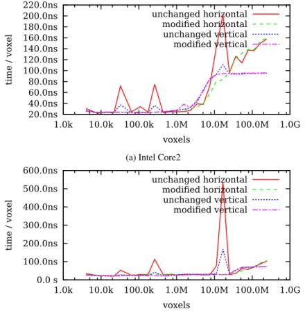
We have measured the performance for both of the de-scribed naive methods in combination with unchanged as well as modified strides. Note that we are talking about the row stride as well as the slice stride. The un-changed stride means that rows and slices are placed without gaps densely one by one. In relation to the sec-ond choice, we have modified the strides in the follow-ing way. Low six bits of the addresses correspond to offsets in cache lines and thus do not directly influence the selection of the cache set. These are set to zero. The other bits are changed to the next highest prime number (the "set" and "tag" in Figure 2). Although a choice of the next highest odd number is sufficient since any odd number is coprime with any power of two. The perfor-mance comparison is shown in Figure 5.
As it can be seen, the performance of unchanged stride is unstable. It exhibits poor properties especially on the power-of-two strides. However, the data has smaller memory footprint. So, if the stride length does not hit the inappropriate value, the entire transform runs faster than in the case with modified stride. In the rest of this paper, we will continue using the modified stride (i.e. prime stride).
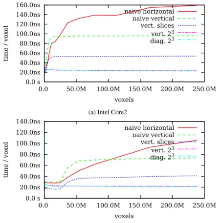
As an intermediate step towards the full 3-D single-loop transform, we have experimented with highly op-timized 2-D transforms followed by a separated filter-ing in the third dimension. The implementation of the optimized 2-D transform is described in our previous paper [2]. Essentially, this transform is computed "out of place" in the single loop by a single-threaded SIMD-optimized 4×4 core. Afterwards, the transform in the third dimension is computed "in place" using the verti-cal vectorization. For 4×4 core approach, the auxiliary buffer of a slice edge size times four has to be allocated.
The buffer is used to transfer information between steps of the vertical vectorization alongyaxis direction. The comparison with the previous two methods is shown in Figure 6. We have plot only the implementations using the modified (stable) strides. The transform performed in the slices outperforms the two naive implementations practically for all sizes on thexaxis.
3.2
True 3-D Approaches
Based on our work in [2], we have created two base-line implementations transforming the entire volume in the single loop. These implementations employing 23cores – first built over the vertical and the second over the diagonal vectorization. Both of them process the data out of a place. The implementation with the diagonal core is inherently accelerated by SIMD in-structions. The vertical implementation does not allow SIMD-optimizations at this stage.
In more detail, both 23cores are composed from three parts. The first part loads the input data from a source memory area. The inner part performs a fragment of the transform computation. Finally, the last part stores the resulting coefficients into a destination area. The first and last parts treat data borders using the symmet-ric extensions.
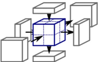
Figure 3: Illustration of 23cubic core. Portions of aux-iliary buffers to update are shown on each side. Access to three auxiliary buffers is required during the inner part of the computation. See Figure 3. This most important part consists of three blocks perform-ing calculations correspondperform-ing to the three dimensions. Each block updates the necessary intermediate results in the corresponding auxiliary buffer. This is followed by scaling of the output coefficients.
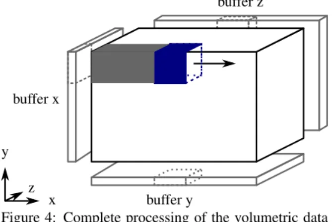
In the most generic variant, each 2-D auxiliary buffer has the same size like the corresponding volume side. The depth of each auxiliary buffer is 4 coefficients for the vertical vectorization or 12 coefficients for the diag-onal one. See Figure 4. This memory consumption can be reduced using a appropriate processing order. When using the horizontal3order, it is not necessary to allo-cate the full side size buffers. It is sufficient to alloallo-cate only the following sizes. One full side size buffer for the first dimension. One edge size buffer for the second dimension. Finally, one point size buffer for the third
x y z buffer x buffer y buffer z
Figure 4: Complete processing of the volumetric data by the 3-D single-loop core. Auxiliary buffer for each dimension is shown on the sides of the volume.
dimension. For instance, considering the vertical vec-torization and 23core, it is sufficient to allocate buffers of total size 4·(sx·sy+sx·2+2·2)elements, where sx,syare sizes of the volume in first two dimensions. Now, we take a closer look on the conjoined scaling. With the scaling constantζ, the scaling of one pair of
coefficients can be written as element-wise multiplica-tion by a scaling vector
Z1(x) =
ζ−1 ζ, (2)
where the coordinatex∈ {0,1}.
In 2-D case, the scaling of one 2×2 block of coeffi-cients can be written as element-wise multiplication by a scaling matrix
Z2(x,y) =Z1(x)·Z1(y), (3) where the coordinatesx,y∈ {0,1}, giving
Z2(x,y) = ζ−2 1 1 ζ2 . (4)
Finally, in 3-D case, the scaling of one 23box of coeffi-cients can be written as element-wise multiplication by a scaling cube
Z3(x,y,z) =Z1(x)·Z1(y)·Z1(z), (5) where x,y,z∈ {0,1}. For better understanding, the slices through thezaxis look like
Z3(x,y,0) = ζ−2 1 1 ζ2 ·ζ−1 = ζ−3 ζ−1 ζ−1 ζ Z3(x,y,1) = ζ−2 1 1 ζ2 ·ζ = ζ−1 ζ ζ ζ3 . (6) We have compared the performance of the two 3-D core approaches to the previous methods. The result can be
Intel Core2 AMD Opteron
method time speedup time speedup
naive horiz. 159.8 1.0 105.7 1.0 naive vert. 100.1 1.6 73.5 1.4 vert. slice 42 53.8 2.9 41.0 2.5 vertical 23 23.3 6.8 21.7 4.7 diagonal 23 22.8 6.9 21.1 4.9 vertical 43 13.5 11.7 12.9 8.0
Table 1: Performance evaluation for large data. Best results are in bold.
seen in Figure 7. Apparently, the 3-D approaches ap-proximately above 1 megavoxel outperform all the pre-vious methods.
Within the context of the vertical vectorization, utiliza-tion of SIMD instrucutiliza-tion set is straightforward. In first two dimensions, 2×2 small 23 cores are merged to-gether in analogous manner as in [2]. In the third di-mension, there is no reason to increase the size of the core as SIMD can be used directly. In all three dimen-sions, the basic building block of the transform is 2×4 core. In this 2×4 core, four steps of the vertical vec-torization are computed in parallel using SIMD instruc-tions. The scaling of coefficients is performed together as the last step of the calculation. As a result, 4×4×2 SIMD-vectorized core was formed.
Although there is no reasonable justification, it can be tempting to build a compact 43core as an analogy to the well-performing 42counterpart. Such core is internally composed of two dependent 4×4×2 sub-cores. How-ever, such a connection may be slightly advantageous due to prefetching of intermediate results. Moreover, the implementation is more regular.
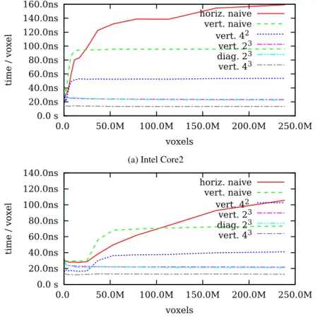
The final comparison is shown in Figure 8. The SIMD-optimized 3-D cores exhibit the best results. The 43 core slightly outperforms the baseline 4×4×2 one. Above initial transients, all the single-loop approaches confirm the linear asymptotic complexity of the discrete wavelet transform.
Based on [2], the single-loop core method can be fur-ther accelerated utilizing the multi-threading. Table 1 summarizes performances and speedups for a volume of 238 megavoxels. The testing platforms are described in Section 1. The speedups are given against the sep-arable method using the horizontal vectorization and the prime stride. The achieved processing time 13 nanoseconds per sample is roughly equivalent to pro-cess 37 frames per second with Full HD resolution (1920×1080 per frame). For 4×4×2 core and any infinite video sequence, only two frames (the currently coded and the immediately preceding) have to be held in memory. The summarizing comparison of all signif-icant approaches is shown in Figure 9.
20.0ns 40.0ns 60.0ns 80.0ns 100.0ns 120.0ns 140.0ns 160.0ns 180.0ns 200.0ns 220.0ns 1.0k 10.0k 100.0k 1.0M 10.0M 100.0M 1.0G time / voxel voxels unchanged horizontal modified horizontal unchanged vertical modified vertical
(a) Intel Core2
0.0 s 100.0ns 200.0ns 300.0ns 400.0ns 500.0ns 600.0ns 1.0k 10.0k 100.0k 1.0M 10.0M 100.0M 1.0G time / voxel voxels unchanged horizontal modified horizontal unchanged vertical modified vertical (b) AMD Opteron
Figure 5: Performance comparison of naive approaches with unchanged and prime strides.
0.0 s 20.0ns 40.0ns 60.0ns 80.0ns 100.0ns 120.0ns 140.0ns 160.0ns 0.0 50.0M 100.0M 150.0M 200.0M 250.0M time / voxel voxels naive horizontal naive vertical vertical slices
(a) Intel Core2
10.0ns 20.0ns 30.0ns 40.0ns 50.0ns 60.0ns 70.0ns 80.0ns 90.0ns 100.0ns 110.0ns 0.0 50.0M 100.0M 150.0M 200.0M 250.0M time / voxel voxels naive horizontal naive vertical vertical slices (b) AMD Opteron
0.0 s 20.0ns 40.0ns 60.0ns 80.0ns 100.0ns 120.0ns 140.0ns 160.0ns 0.0 50.0M 100.0M 150.0M 200.0M 250.0M time / voxel voxels naive horizontal naive vertical vert. slices vert. 23 diag. 23
(a) Intel Core2
0.0 s 20.0ns 40.0ns 60.0ns 80.0ns 100.0ns 120.0ns 140.0ns 0.0 50.0M 100.0M 150.0M 200.0M 250.0M time / voxel voxels naive horizontal naive vertical vert. slices vert. 23 diag. 23 (b) AMD Opteron
Figure 7: Performance comparison of two baseline 3-D approaches with previous ones.
0.0 s 20.0ns 40.0ns 60.0ns 80.0ns 100.0ns 120.0ns 140.0ns 0.0 50.0M 100.0M 150.0M 200.0M 250.0M time / voxel voxels vert. 23 diag. 23 vert. 4×4×2 vert. 43
(a) Intel Core2
0.0 s 20.0ns 40.0ns 60.0ns 80.0ns 100.0ns 120.0ns 140.0ns 0.0 50.0M 100.0M 150.0M 200.0M 250.0M time / voxel voxels vert. 23 diag. 23 vert. 4×4×2 vert. 43 (b) AMD Opteron
0.0 s 20.0ns 40.0ns 60.0ns 80.0ns 100.0ns 120.0ns 140.0ns 160.0ns 0.0 50.0M 100.0M 150.0M 200.0M 250.0M time / voxel voxels horiz. naive vert. naive vert. 42 vert. 23 diag. 23 vert. 43
(a) Intel Core2
0.0 s 20.0ns 40.0ns 60.0ns 80.0ns 100.0ns 120.0ns 140.0ns 0.0 50.0M 100.0M 150.0M 200.0M 250.0M time / voxel voxels horiz. naive vert. naive vert. 42 vert. 23 diag. 23 vert. 43 (b) AMD Opteron
Figure 9: Summarizing performance comparison of all approaches under the prime stride.
4
CONCLUSIONS
We have presented a true single-loop approach designed to transform 3-D data. The proposed method can be understood as a streaming unit which visits every in-put as well as outin-put data element only once. The core can further be improved by exploiting suitable SIMD instruction set. The best of proposed methods reaches speedup 11×on Intel and 8×on AMD compared to the naive implementation. The measurements confirm the linear theoretical complexity of the transform in 3-D. In absolute numbers, the best method can transform a data sample in 13 nanoseconds what is roughly equivalent to transform 37 frames per second in Full HD.
As a future work, our methods can be parallelized by multithreading. For real applications, it can be neces-sary to perform several levels of such decomposition. Acknowledgements
This work has been supported by the IT4Innovations Centre of Excellence (no. CZ.1.05/1.1.00/02.0070).
REFERENCES
[1] D. Barina and P. Zemcik. Minimum memory vec-torisation of wavelet lifting. InAdvanced Con-cepts for Intelligent Vision Systems, volume 8192 ofLecture Notes in Computer Science, pages 91– 101. Springer, 2013. ISBN 978-3-319-02894-1. doi: 10.1007/978-3-319-02895-8_9.
[2] D. Barina and P. Zemcik. Vectorization and paral-lelization of 2-D wavelet lifting. Journal of Real-Time Image Processing, 2015. ISSN 1861-8200. doi: 10.1007/s11554-015-0486-6.
[3] E. Belyaev, K. Egiazarian, and M. Gabbouj. Low complexity bit-plane entropy coding for 3-D DWT-based video compression. InProceedings of SPIE, volume 8304, 2012. doi: 10.1117/12. 912017.
[4] G. Bernabe, J. Garcia, and J. Gonzalez. Re-ducing 3D fast wavelet transform execution time using blocking and the streaming SIMD exten-sions. Journal of VLSI signal processing systems for signal, image and video technology, 41(2): 209–223, 2005. ISSN 0922-5773. doi: 10.1007/ s11265-005-6651-6.
[5] G. Bernabe, R. Fernandez, J. M. Garcia, M. E. Acacio, and J. Gonzalez. An efficient implemen-tation of a 3D wavelet transform based encoder
on hyper-threading technology. Parallel Comput-ing, 33(1):54–72, 2007. ISSN 0167-8191. doi: 10.1016/j.parco.2006.11.011.
[6] G. Bernabe, G. Guerrero, and J. Fernandez. CUDA and OpenCL implementations of 3D fast wavelet transform. InIEEE Third Latin American Symposium on Circuits and Systems (LASCAS), pages 1–4, Feb. 2012. doi: 10.1109/LASCAS. 2012.6180318.
[7] S. Chatterjee and C. D. Brooks. Cache-efficient wavelet lifting in JPEG 2000. InProceedings of the IEEE International Conference on Multime-dia and Expo (ICME), volume 1, pages 797–800, 2002. doi: 10.1109/ICME.2002.1035902. [8] D. Chaver, C. Tenllado, L. Pinuel, M. Prieto, and
F. Tirado. Wavelet transform for large scale im-age processing on modern microprocessors. In High Performance Computing for Computational Science – VECPAR 2002, volume 2565 of Lec-ture Notes in Computer Science, pages 549–562. Springer, 2003. ISBN 978-3-540-00852-1. doi: 10.1007/3-540-36569-9_37.
[9] D. Chaver, C. Tenllado, L. Pinuel, M. Prieto, and F. Tirado. Vectorization of the 2D wavelet lifting transform using SIMD extensions. InProceedings of the International Parallel and Distributed Pro-cessing Symposium (IPDPS), page 8, 2003. doi: 10.1109/IPDPS.2003.1213416.
[10] C. Chrysafis and A. Ortega. Minimum memory implementations of the lifting scheme. In Pro-ceedings of SPIE, Wavelet Applications in Signal and Image Processing VIII, volume 4119 ofSPIE, pages 313–324, 2000. doi: 10.1117/12.408615. [11] A. Cohen, I. Daubechies, and J.-C.
Feau-veau. Biorthogonal bases of compactly supported wavelets. Communications on Pure and Applied Mathematics, 45(5):485–560, 1992. ISSN 1097-0312. doi: 10.1002/cpa.3160450502.
[12] I. Daubechies and W. Sweldens. Factoring wavelet transforms into lifting steps. Journal of Fourier Analysis and Applications, 4(3):247– 269, 1998. ISSN 1069-5869. doi: 10.1007/ BF02476026.
[13] U. Drepper. What every programmer
should know about memory, 2007. URL
http://www.akkadia.org/drepper/ cpumemory.pdf.
[14] J. Franco, G. Bernabe, J. Fernandez, and M. Ujal-don. Parallel 3D fast wavelet transform on many-core GPUs and multimany-core CPUs. Procedia Com-puter Science, 1(1):1101–1110, 2010. ISSN 1877-0509. doi: 10.1016/j.procs.2010.04.122. ICCS 2010.
[15] V. Galiano, O. Lopez-Granado, M. Malumbres, and H. Migallon. Multicore-based 3D-DWT video encoder. EURASIP Journal on Advances in Signal Processing, 2013(1):84, 2013. doi: 10.1186/1687-6180-2013-84.
[16] R. Kutil. A single-loop approach to SIMD par-allelization of 2-D wavelet lifting. In Proceed-ings of the 14th Euromicro International Confer-ence on Parallel, Distributed, and Network-Based Processing (PDP), pages 413–420, 2006. ISBN 0-7695-2513-X. doi: 10.1109/PDP.2006.14. [17] O. Lopez, M. Martinez-Rach, P. Pinol,
M. Malumbres, and J. Oliver. A fast 3D-DWT video encoder with reduced memory usage suitable for IPTV. In 2010 IEEE Inter-national Conference on Multimedia and Expo (ICME), pages 1337–1341, July 2010. doi: 10.1109/ICME.2010.5583570.
[18] P. Meerwald, R. Norcen, and A. Uhl. Cache issues with JPEG2000 wavelet lifting. InVisual Commu-nications and Image Processing (VCIP), volume 4671 ofSPIE, pages 626–634, 2002.
[19] A. Shahbahrami, B. Juurlink, and S. Vassiliadis. Improving the memory behavior of vertical filter-ing in the discrete wavelet transform. In Proceed-ings of the 3rd conference on Computing fron-tiers (CF), pages 253–260. ACM, 2006. ISBN 1-59593-302-6. doi: 10.1145/1128022.1128056. [20] W. Sweldens. The lifting scheme: A
custom-design construction of biorthogonal wavelets. Ap-plied and Computational Harmonic Analysis, 3 (2):186–200, 1996. ISSN 1063-5203.