Study of supersymmetric signals with
R
-parity violation in ATLAS at LHC
Emma Torr ´o Pastor
Dirigida por
Vasiliki Mitsou y Salvador Mart´ı i Garcia
Tutor: Jos´e Ros Pallares
Doctorado en F´ısica
Diciembre 2012
Facultat de F´ısica
Departament de F´ısica Te `orica
Universitat de Val`encia Estudi General
i La Dra.Vasiliki A. Mitsouy el Dr.Salvador Mart´ı i Gracia
CERTIFICAN:
Que la presente memoria, ”Study of supersymmetric signals with R-parity violation at
ATLAS/LHC”, ha sido realizada bajo nuestra direcci ´on en elDepartamento de F´ısica Te´oricade
laUniversitat de Val`enciapor Emma Torr ´o Pastor y constitutye su tesis para optar al grado de doctora en F´ısica por la Universitat de Val`encia.
Y para que conste, firmamos el presente Certificado en Burjassot a 19 de Diciembre de 2012.
Contents
1 Introduction 1
1.1 The Standard Model . . . 1
1.1.1 Limitations of the Standard Model . . . 2
1.1.2 Beyond the Standard Model theories . . . 3
1.2 The LHC and the ATLAS detector . . . 5
1.3 Searches for SUSY in the ATLAS detector . . . 5
1.4 Experimental constraints onRPV SUSY scenarios . . . 6
2 Experimental framework 7 2.1 The Large Hadron Collider (LHC) . . . 7
2.2 The LHC experiments . . . 11
2.2.1 A Toroidal LHC ApparatuS (ATLAS) . . . 12
2.2.2 Compact Muon Solenoid (CMS) . . . 13
2.2.3 LHCb . . . 14
2.2.4 A Large Ion Collider Experiment (ALICE) . . . 15
2.3 ATLAS . . . 16 2.3.1 Inner Detector . . . 17 2.3.2 Calorimeters . . . 19 2.3.3 Muon system . . . 20 2.3.4 Forward detectors . . . 21 2.3.5 Trigger system . . . 22
2.3.6 Object reconstruction in ATLAS . . . 23
2.4 LHC Computing GRID . . . 30
3 Theoretical framework 31 3.1 Supersymmetry . . . 31
3.1.1 Introduction . . . 31
3.1.2 Formal description of SUSY . . . 34
3.1.3 MSSM . . . 39
3.1.4 mSUGRA . . . 43
3.2 R-parity violation (RPV) . . . 44
3.2.1 BilinearR-parity violation (bRPV) . . . 46
4 Monte Carlo analysis 51 4.1 Introduction . . . 51
4.2 Analysis strategy . . . 52
4.3 Simulated samples . . . 53
4.3.1 Signal samples . . . 53 iii
4.3.2 SM samples . . . 58
4.4 Trigger and preselection . . . 58
4.4.1 Analysis at 7 TeV . . . 59 4.4.2 Analysis at 10 TeV . . . 61 4.4.3 Analysis at 14 TeV . . . 62 4.5 SM background suppression . . . 63 4.5.1 Analysis at 7 TeV . . . 64 4.5.2 Analysis at 10 TeV . . . 69 4.5.3 Analysis at 14 TeV . . . 71
4.5.4 Conclusions on the SM background suppression . . . 71
4.6 Combinatorial background study . . . 73
4.6.1 Analysis at 7 TeV . . . 74
4.6.2 Analysis at 10 TeV . . . 81
4.7 Invariant mass of muon+jets . . . 84
4.8 Systematic uncertainties . . . 85
4.9 Conclusion . . . 86
5 Searches for bRPV SUSY with 2011 ATLAS data 89 5.1 Analysis overview . . . 90
5.1.1 Signal regions . . . 91
5.1.2 Control regions . . . 91
5.1.3 Background determination in the signal regions . . . 92
5.1.4 Results interpretation . . . 93
5.1.5 Motivation of analysis setup . . . 93
5.2 Samples: data, bRPV and backgrounds . . . 94
5.2.1 Data . . . 94
5.2.2 MC background . . . 94
5.2.3 bRPV grid . . . 95
5.3 Definition of objects . . . 96
5.3.1 Jets andb-jets . . . 96
5.3.2 Electrons . . . 97
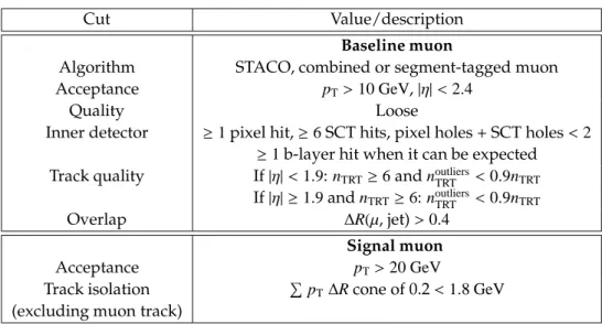
5.3.3 Muons . . . 98
5.3.4 Missing transverse energy (EmissT ) . . . 99
5.3.5 Pile-up treatment . . . 99
5.3.6 Liquid Argon (LAr) hole veto . . . 99
5.4 Trigger and preselection . . . 99
5.4.1 Triggers . . . 100
5.4.2 Event preselection . . . 100
5.5 Event selection . . . 102
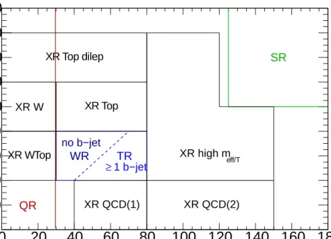
5.5.1 Definition of signal regions . . . 102
5.5.2 QCD background estimation . . . 109
5.5.3 W and top background estimation . . . 110
5.5.4 Initial and final state radiation . . . 112
5.5.5 Contamination from cosmic events . . . 112
5.5.6 SUSY signal . . . 114
5.5.7 Comparison between bilinearRPV andRPC SUSY . . . 125
5.6 Results . . . 127
5.6.1 Fit setup . . . 127
CONTENTS v
5.6.3 Fit results . . . 128
5.6.4 Impact of systematic uncertainties . . . 129
5.6.5 Limits on visible cross sections and discoveryp-values . . . 129
5.7 Conclusions . . . 132
6 AtlFast-II validation for SUSY 135 6.1 Introduction . . . 135 6.2 AtlFast-II description . . . 136 6.3 Validation setup . . . 136 6.4 Object definition . . . 139 6.5 Results . . . 140 6.5.1 Description of objects . . . 140
6.5.2 Description of event selection efficiencies . . . 145
6.6 Summary and proposal . . . 146
7 Conclusions 149 8 Epilogue 153 8.1 Analysis follow up. . . 153
9 Resumen en castellano 157 9.1 Introducci ´on . . . 157
9.1.1 El LHC y el detector ATLAS . . . 157
9.1.2 Supersimetr´ıa . . . 158
9.2 An´alisis con muestras de Monte Carlo . . . 160
9.2.1 Definici ´on de la se ˜nal . . . 160
9.2.2 Trigger y preselecci ´on . . . 161
9.2.3 Supresi ´on del fondo del SM . . . 162
9.2.4 Estudio sobre el fondo combinatorio . . . 164
9.2.5 Masa invariante mu ´on+jets y conclusi ´on . . . 165
9.3 B ´usqueda de bRPV-SUSY con datos de ATLAS de 2011 . . . 167
9.3.1 Regiones de se ˜nal y de control . . . 167
9.3.2 Muestras: datos, fondos del SM y bRPV . . . 168
9.3.3 Trigger y preselecci ´on . . . 169
9.3.4 Selecci ´on de sucesos . . . 170
9.3.5 Resultados . . . 172
9.3.6 Conclusiones . . . 174
9.4 Validaci ´on de AF-II para SUSY . . . 175
9.4.1 Resultados . . . 175
9.4.2 Propuesta . . . 176
9.5 Conclusiones . . . 176
9.6 Seguimiento del an´alisis . . . 177
A Monte Carlo sample details 179 A.1 SUSY production processes . . . 179
A.2 Monte Carlo signal samples for the 1muon+2jets analyses . . . 179
B Backup plots for the 10 TeV and 14 TeV analyses 183
B.1 Event selection: SM background for the 10 TeV analysis . . . 183 B.2 Event selection: SM background for the 14 TeV analysis . . . 184 B.3 Combinatorial background study for the 10 TeV analysis . . . 185
C Combinatorial background study for differentpµTthresholds 187
D Further details on the comparisonRPC versus bRPV 189
E OS muon + electron cut flow details 195
Chapter 1
Introduction
Supersymmetry (SUSY) [1] is one of the most promising theories providing a solution for many of the current open questions in the Standard Model (SM) [2]. Among the several possible scenarios that SUSY presents, there is a particularly interesting one due to its relation with neutrino physics. In this model the spontaneous breaking ofR-parity (see Section 1.1.2) gives vacuum expectation values (vevs) to neutrinos, providing a “vev-seesaw” mechanism that leads to neutrino masses (see Section 3.2.1). Below the scale of these vevs,R-parity breaking is explicit through bilinear lepton number violating terms. The same parameters that induce neutrino masses and mixings are responsible for the decay of the lightest supersymmetric particle (LSP). In this thesis two studies have been developed in order to search for a proof on the existence or not of SUSY with bilinearR-parity violation (bRPV) in Nature, within the accessible mass range. The first part of the thesis is devoted to the determination of the discovery potential of the bRPV model in the ATLAS detector at the Large Hadron Collider (LHC) [3, 4] and to the possible measurement of the LSP mass, at three different working centre-of-mass energies for the LHC of √s = 7, 10 and14 TeV. Since one of the characteristics of this model is the
presence of muons in a large percentage of events (see Chapter 4) and by high jet multiplicity, the optimal approach for its search is to consider one muon and several jets in the final state. In this case, a search implying one muon and two jets is presented using Monte Carlo (MC) simulated samples of bRPV-SUSY and SM background. This work is documented in the ATLAS Internal Note in Ref. [91]. The second part of the thesis is an inclusive search for bRPV with real ATLAS data taken from 2011 LHC collisions at7 TeV, considering a grid of points in the bRPV parameter space. In this analysis, final states containing one muon and at least three or four jets are selected. After taking into account all possible sources of uncertainties, no significant excess of events has been observed over the expected SM background. This has led to the first hadron colliders exclusion limits set on bRPV models, which has been published in Physical Review D [113] and documented in detail in the ATLAS Internal Note in Ref. [114]
1.1
The Standard Model
The Standard Model of High Energy Physics provides the current most accurate description of the Elementary Particle Physics phenomenology. It has been tested up to theTeVscale with remarkably successful results by experiments such as LEP [5], Tevatron [6], ATLAS [7–9] and
CMS [10], with the Higgs boson being the only remaining piece to be discovered1). These
experiments also give clear hints of additional structure, pointing to some New Physics (NP) beyond the SM [13].
1.1.1
Limitations of the Standard Model
There is a 17 orders of magnitude gap between the highest physical scale tested, the sponta-neous electroweak symmetry breaking scale (ΛEW ∼O(100 GeV)) and the next known physical
scale, the Planck mass (MP ∼O(1019GeV)) [14]. There are several limitations which the SM is
unable to cover if it is to be valid up to the Planck mass. Some of them are outlined below.
1. Hierarchy problem. The Higgs boson is the only scalar field in the SM, which makes it
special in that loop corrections to scalar fields squared masses are quadratically divergent: they are proportional to the squared cut-off of the theory,Λ2. This is known as thehierarchy
problem.
2. Matter-antimatter asymmetry. The observed asymmetry between matter and antimatter
in the Universe have not been explained so far within the framework of the SM.CP vi-olation in the SM predicts matter and antimatter not to behave in the exact same way. Still, some additional mechanism would be needed to explain the amazing dominance of matter over antimatter in the Universe.
3. Neutrino masses. Neutrinos are massless particles in the SM. However, it is
experimen-tally known that this is not the case, and lower limits on their masses have been set [15,16].
4. Cosmological consideration. It is estimated that only ∼ 4%of the Universe density is
made of baryonic matter. The rest of the universe is composed of∼ 24%Dark Matter (DM) and∼72%Dark Energy [17], for neither of which the SM provides any explanation nor suitable candidates.
5. Grand Unification. Unification of all the fundamental interactions is an attractive
con-cept. In the SM, strong and electroweak interactions are described independently and their running coupling constants do not get unified at any higher energy. A Grand Unify-ing Theory (GUT) [18,19] would make these two interactions to converge in one universal gauge coupling defined at the grand unification scale.
6. The fermion mass hierarchy problem. The existence of three fermion families has been
experimentally tested. Nevertheless, the SM gives no prediction on the number of fermion generations. Furthermore, there is no explanation or prediction of their masses, which are observed to have hierarchical pattern spanning over six orders of magnitude between the top quark and the electron, or the difference even greater between these two and the neutrinos, which are lighter still by many orders of magnitude.
7. Gravity. Even though it is one of the fundamental forces of Nature, it is not included in
the SM.
Thus, it seems clear that the SM is not the ultimate Theory, but an effective field theory which is able to explain Nature with great accuracy up to a certain energy scale beyond which it will need to be extended or included in a more complete theory. Several theories have been devel-oped in this direction, such as Supersymmetry, theories involving extra dimensions like String Theories [20] or technicolor [21]. Among them, Supersymmetry is one of the best motivated.
1)During the writing of this thesis, the ATLAS and CMS experiments announced the observation of a particle with mass at125−126 GeVcompatible with the SM Higgs boson [11, 12]
1.1. THE STANDARD MODEL 3
1.1.2
Beyond the Standard Model theories
Several beyond the Standard Model theories have been developed involving higher symme-tries of one form or another or new spatial dimensions. Some examples of the most ambitious such theories are outlined in the following.
· Supersymmetry
Supersymmetry [1] is one of the most promising approaches providing a solution for some of the current problems of the Standard Model. It is the maximal possible extension of the Lorentz group. Through its generatorsQ,Q†, it relates particles with the same quantum numbers, differing by±1/2unit of spin:
Q|bosoni=|fermioni, Q|fermioni=|bosoni.
This implies that every SM particle has a superpartner with the same quantum numbers except for the spin. If SUSY is actually a symmetry of Nature, it must be a broken one so that superpartners masses are higher than those of the SM particles.
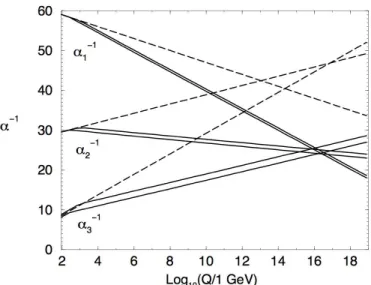
An important characteristic of SUSY is that it predicts a Higgs mass free of quadrati-cally divergent quantum corrections due to the cancellation —to all orders in pertur-bation theory— of each of such divergent terms by the analogous term for the super-partner. Another attractive aspect is that it predicts grand unification at a scaleMGUT ≃
O(1016GeV) [18] since the running of the couplings is affected by the inclusion of the su-persymmetric particles. Most of the scenarios considered within SUSY assume the conser-vation of both baryon and total lepton number in order to avoid a (relatively) fast proton decay. This scenario is referred to asR-parity conserving SUSY.R-parity is a quantum number defined as
PR=(−1)3(B−L)
+2s
(1.1) whereBstands for Baryon number,Lfor Lepton number andsfor spin.
In the case ofR-parity being conserved, the lightest supersymmetric particle is neutral and stable, becoming an ideal Dark Matter candidate. Nevertheless this assumption can be relaxed in several ways. In the case thatR-parity is not conserved there are still some possibilities for DM candidates such as the gravitino [22] or the axino [23]. Furthermore, in the case ofR-parity violation (RPV) through the bilinear term (see Section 3.2.1), neutrinos acquire mass in a natural way. Hence, Supersymmetry is a very complete theory, able to solve many of the above mentioned limitations of the SM. A detailed description of SUSY is available in Chapter 3.
From the experimental point of view, the decays of supersymmetric particles, such as squarks and gluinos, would involve cascades which, ifR-parity is conserved, always con-tain two stable LSPs. As the LSP would interact only weakly with the detector, the expe-riment would measure a significant missing transverse energy,Emiss
T , in the final state. In
the caseR-parity is not conserved, the LSP would decay into SM particles. The rest of the cascade would result in a number of leptons and jets.
· Extra dimensions
Several new models propose the existence of extra dimensions [24] containing additional space dimensions on top of the usual 4-dimensional manifold, while gravity can propa-gate through all the dimensions. Then in these models, the observed weakness of the
gravitational interaction (compared to the others) is not fundamental but a mere conse-quence of the existence of such extra dimensions. Moreover, these extra dimensions are assumed to be curled up, such that their small size explains why they would be invisible to us.
Extra dimensions may become detectable at very high energies. One possible experi-mental signature could lead to the emission of gravitons which escape into extra dimen-sions and therefore generate Emiss
T or miniature black-hole production with spectacular
decays involving democratic productions of fundamental final states such as jets, leptons, photons, neutrinos andW andZbosons [25]. Also Kaluza-Klein excitations may appear, which manifest themselves asZ-like resonances withO(TeV)separations in mass.
· Little Higgs
Little Higgs models [26] are based on the idea that the Standard-Model-like Higgs boson is a pseudo-Goldstone boson arising from some spontaneous global symmetry breaking at the TeV energy scale. This idea arose from the observation that, if certain global sym-metries are broken only by the interplay between two or more coupling constants, then the Higgs-mass-squared is free from quadratic divergences at one loop. However, these cancellations do not continue in higher orders, unlike the case of supersymmetry. This “collective” symmetry breaking is the essential ingredient in little Higgs theories, which are weakly-coupled extensions of the SM describing physics up at an energy scale∼ 10 TeV. Such models necessarily predict the existence of additional particles. The spectrum of new particles varies somewhat from one little Higgs model to another, but all of them predict at least one vector-like quark at theTeVscale, along with extra gauge bosons and scalars.
· Two-Higgs-doublets model
The minimal version of the Standard Model contains one complex Higgs doublet, result-ing in one physical neutralCP-even Higgs boson after electroweak symmetry breaking. However, the SM is not likely to be the ultimate theory and some theories (such as super-symmetry) have been developed containing a scalar Higgs sector corresponding to that of a two-Higgs-doublet model (2HDM) [27].
There are two possible cases for general 2HDM. In the first case, there is no energy range for which the effective low-energy theory contains only one light Higgs boson. In the second case, oneCP-even neutral Higgs boson is significantly lighter than the other Higgs bosons of the model. In particular, in the so-called decoupling limit [28] where the mass scale of the heavier Higgs bosons is much higher than the mass of the lightest Higgs and all dimensionless Higgs self-coupling parametersλi .O(1), the properties of the lightest
Higgs boson are nearly indistinguishable from those of the SM Higgs boson.
All these theories are subject of extensive searches in the LHC. Apart from the already men-tioned ones, other signatures belonging to NP will be investigated with the ATLAS data from LHC collisions. New heavy gauge bosonsW’ andZ’ bosons could be accessible for masses up to severalTeV. Anomalous high-mass di-jet production and searches for flavour-changing neutral currents and lepton flavour violation may also open a window onto New Physics. The LHC has been constructed and is currently in operation at CERN, the European Laboratory for Particle Physics near Geneva.
1.2. THE LHC AND THE ATLAS DETECTOR 5
1.2
The LHC and the ATLAS detector
The Large Hadron Collider is currently the largest ever built particle accelerator and collider. It is situated at CERN near Geneva, in the existing 26.7 km round tunnel that was constructed between 1984 and 1989 for the Large Electron-Positron Collider (LEP) [5].
The LHC aims to discover the Higgs boson, to perform precision measurements of the Stan-dard Model parameters and to reveal the Physics beyond it, with proton-proton collisions with centre-of-mass energies of up to √s = 14 TeV. In addition to the huge Physics program with
ppcollisions, the LHC is also designed to study physics of strongly interacting matter and the quark-gluon plasma by colliding heavy ions (Pb) with an energy of 2.8TeVper nucleon.
Most of the interesting processes to be studied in the LHC are expected to have very small cross sections and hence a huge number of collisions is needed in order to get enough statistics in the physics analyses. This is the main reason for the formidable luminosity (L=1034cm−2s−1)
and resulting interaction rate the LHC is designed to obtain.
Installed at the LHC there are two general purpose experiments, ATLAS [7–9] and CMS [10], both aiming to explore the above mentioned Physics. ATLAS is a general purpose experiment whose design has been optimised to be sensitive to a wide range of physics signatures in order to fully exploit the discovery potential of the hadron collider. It is composed of different subde-tectors, each of them specialised in the identification of a specific type of particle. The Inner De-tector ensures a robust pattern recognition, precise vertex measurements and, with the help of a solenoid magnet, good momentum determination. The Electromagnetic Calorimeter is used for the identification and energy measurements of electrons and photons. The Hadronic Calorime-ter measures hadronic jets and missing energy. The Muon SpectromeCalorime-ter is designed for muon detection and momentum identification. The whole detector is embedded in a toroidal magnet which generates strong bending power to ensure a proper measure of all particle features.
The LHC started working in a stable mode at the end of 2010 and so far it has released
5.61 fb−1of integrated luminosity for √s=7 TeVcollisions and over 19fb−1of integrated
lumi-nosity for √s=8 TeVcollisions. The ATLAS detector is having a really good response and it has
collected5.25 fb−1of integrated luminosity for √s=7 TeVdata and about18 fb−1of integrated
luminosity for √s=8 TeVdata with excellent detector conditions.
A more detailed description of the LHC and its larger experiments follows in Chapter 2.
1.3
Searches for SUSY in the ATLAS detector
Supersymmetry is one of the best motivated extensions of the Standard Model, so its study is one of the primary goals of the Large Hadron Collider. If SUSY exists at theTeVscale, there are good perspectives for discovering SUSY particles at the LHC.
Standard searches for generic SUSY involveR-parity conservation, implying that sparticles must be produced in pairs and that the lightest sparticle (LSP) must be stable. The LSP is a supersymmetric candidate for dark matter, and should presumably have neither electric charge nor color charge; otherwise, it would bind to regular matter and form anomalous heavy nuclei that have never been observed [29]. It is the weakly-interacting nature of the LSP that provides the classic supersymmetric signature of missing (transverse) energy, giving signatures involv-ingEmiss
T , jets, and possibly leptons.
Different strategies are designed for the search of a wide spectrum of possible signatures arising in different SUSY models. There is an endless list of analyses covering many configu-rations of final states (e.g. different number of leptons, photons, including or notb-tagged jets, etc. as well as specific searches for non-standard SUSY including electron-muon resonances,
long-lived R-hadrons, displaced vertices, etc.) the results of which can be found in the ATLAS SUSY Public Results Webpage [30].
All these searches are possible thanks to the simulation of the corresponding scenarios for particular sets of points in the parameter space. Since large numbers of signal points must be studied, these scans are in some cases based on fast, parameterised detector simulation which will be discussed in Chapter 6.
1.4
Experimental constraints on
R
PV SUSY scenarios
Several exclusion results onRPV signatures from high-energy experiments are available, leading to constraints fulfilled by sufficiently high LSP masses (see e.g. Ref. [31] for searches at LEP or Ref. [32] discussingRPV searches at the Tevatron). Other RPV searches are based on HERA results [33], results from Belle/Babar [34] or neutrino laboratories and astrophysics data [35]. It should also be noted that there have been new constraints on sparticle masses as-suming trilinearRPV couplingsλ123orλ122by the ATLAS [36–38] and CMS [39] collaborations.
Since these results are based on different assumptions and lead to other decay modes of the LSP, there is no direct effect on the analyses performed for this thesis. Nevertheless and as it will be commented in Chapter 4, some similarities between differentRPV scenarios make it possible to reinterpret results based on bRPV within a trilinearRPV context. The impact of bounds from neutrinoless double beta decay or rare leptonic decays for bRPV is discussed in Ref. [?,101], and an extensive discussion on the constraints on the size ofRPV couplings from Cosmology and Astrophysics including the proton decay can be found in Ref. [?]. All these constraints have been taken into account for this work.
Chapter 2
Experimental framework
2.1
The Large Hadron Collider (LHC)
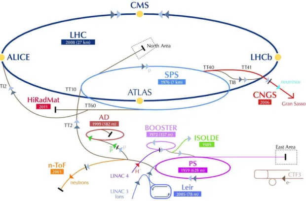
Figure 2.1:Drawing of the LHC and the experiments therein.
The Large Hadron Collider (LHC) [3,4] is currently the largest ever built particle accelerator and collider. It is placed at the European Laboratory for Particle Physics (CERN) near Geneva, in the existing 26.7 km round tunnel that was constructed for the Large Electron-Positron Collider (LEP) [5].
The prime motivation of the LHC is to shed light on the mathematical consistency of the Standard Model at energy scales above1 TeV. It should perform precision measurements of the already known phenomenology and elucidate the nature of electroweak symmetry breaking for which the Higgs mechanism is presumed to be responsible. It also aims at revealing the Physics beyond the SM, with proton-proton (pp) collisions with centre-of-mass energies of up to14 TeV. It will lead to the investigation of various alternatives to the SM which invoke new symmetries, new forces or new constituents. Furthermore, there are high hopes for discoveries that could pave the way toward a unified theory.
In addition to the huge Physics program with ppcollisions, the LHC is also designed to study physics of strongly interacting matter and the quark-gluon plasma by colliding heavy ions (Pb) with an energy of2.8 TeVper nucleon.
Most of the interesting processes to be studied in the LHC are expected to have very small cross sections and hence a huge number of collisions is needed in order to get enough statistics in the physics analyses. This is the main reason for the formidable luminosity (L=1034cm−2s−1)
and resulting interaction rate the LHC is designed to obtain. In addition, the higher the LHC energy reaches, the larger the spectrum of possible processes generated to be investigated is. The exploration of rare events in the LHC collisions therefore requires both high beam energies and high beam intensities.
The number of a certain physics process events generated in the LHC collisions is given by:
Nprocess=Lσprocess, (2.1)
whereσprocessis the cross section for the process under study andLthe integrated luminosity
which is defined by
L=
Z
Ldt, (2.2)
whereLis the machine instantaneous luminosity. The machine luminosity depends only on the beam parameters, such as the number of bunches per beam (each beam has an internal structure as they are arranged in bunches), the number of particles per bunch, the revolution frequency and the beam size at the interaction point (IP).
Theoretically, the luminosity can be increased by increasing both the number of particles per bunch and the number of bunches, and by reducing the intersection area between them. Nevertheless, this is hard to achieve in practice since the major limitation comes from beam-to-beam effects when particles are close to the interaction point. The proton bunch creates a hugely non-linear electromagnetic field which modifies the trajectory of particles from their ideal orbits. The force on the particle is proportional to the number of protons on the bunch, and limits the bunch intensity toO(1011)protons.
The considerable amount of Bremsstrahlung radiation for the required high energies, ex-cludes the use of electrons in this collider. In addition, the high beam intensity required for a luminosity ofL =1034cm−2s−1 excludes the use of anti-proton beams, and hence excludes the
particle-anti-particle collider configuration of a common vacuum and magnet system for both circulating beams, as used for example in the Tevatron.
The LHC magnets have to accelerate two beams of equally charged particles but in opposite directions and there are obvious room constraints. To bend the trajectory of the7 TeVproton beams along the LHC tunnel, a magnetic field of up to a8.33Tesla is generated by1232 su-perconducting dipole magnets. The tunnel has eight straight sections and eight arcs and lies between45 m and 170m below the surface sloping towards the L´eman lake. In the arcs it has an internal diameter of3.7m, which makes it extremely difficult to install two completely separate proton rings. This hard limit on space led to the adoption of the twin-bore magnet design, that consists of two sets of coils and beam channels within the same mechanical struc-ture and cryostat. The disadvantage of the twin-bore design is that the rings are magnetically coupled, which adversely affects flexibility. This is why the Superconducting Super Collider (SSC) [40] was designed with separate rings with counter-rotating beams. The coils are made of niobium-titanium (NbTi) which is a material that allows to reach the superconducting regime when it is at 1.9 K [4]. In addition, 392 quadrupolar magnets are used to focus and correct the beams. There are also sextupole, octupole and decapole magnets mainly for compensating the systematic non-linearities.
2.1. THE LARGE HADRON COLLIDER (LHC) 9 The LHC is therefore designed as a proton-proton collider with separate magnet fields and vacuum chambers in the main arcs and with common sections only at the insertion regions (IR) where the experimental detectors are located. Together with the large number of bunches (with a nominal number of 2808 for each proton beam), and a nominal bunch spacing of 25 ns, the long common beam pipe implies 34 parasitic collision points at each experimental insertion region. For four experimental IRs, this implies a total of 136 unwanted collision points. Dedicated crossing angle orbit bumps separate the two LHC beams left and right from the IP in order to avoid collisions at these parasitic collision points.
Figure 2.2:Schematic layout of the CERN accelerator complex (not to scale).
The LHC is linked through two transfer tunnels to the CERN accelerator complex, which is used as injector (see Figure 2.2). Protons are generated at the LINAC2 linear accelerator and sent to the Proton Synchrotron Booster (PSB) where the energy is increased to1.4 GeV. In the Proton Synchrotron (PS) they are accelerated up to25 GeVbefore the SPS accelerates the beam to450 GeVand injects it into the LHC.
In order to obtain the design instantaneous luminosity, the machine went through a series of intermediate steps. At the first phase the machine ran with a luminosity ranging from3× 1028cm−2s−1up to2×1031cm−2s−1. A second phase with a luminosity of1032cm−2s−1followed and at the end of the 2011 data-taking period a luminosity of3.65×1033cm−2s−1was achieved
During 2012 the LHC is producing collisions at √s=8 TeVwith∼19 fb−1collected so far
with a peak luminosity of7.7×1033 cm−2s−1. Starting from February 2013, a20-month long
shutdown is scheduled, mainly for maintenance and technical consolidation of the machine performance and some concerning experiment issues. After that, from 2014 on, operation is expected with an increase of its energy from the current energy of8 TeVto13 TeV or14 TeV
reaching the nominal luminosity of1034 cm−2s−1, with few hundreds inverse femptobarns of
integrated luminosity, and a bunch-crossing time of 25 ns, i.e. at a rate of 40 MHz. In 2018 the LHC phase I will end and a shutdown is scheduled with the goal of reaching a high luminosity of2×1034cm−2s−1. In the period 2019 - 2021 the high luminosity LHC (HL-LHC) phase will take
place, collecting data at √s=14 TeV. The last shutdown is scheduled for 2022-2023 at HL-LHC
with the goal of reaching5×1034cm−2s−1.
With respect to the LHC running with Pb-Pb nuclei collisions for the year 2011, a peak lumi-nosity ofL=5.1×1026cm−2s−1was reached with collisions at √s
NN =2.76 TeV.
The data considered in the search performed in this thesis (see Chapter 5) were delivered by the LHC and collected by the ATLAS detector during 2011 at √s=7 TeV. The magnificent
behaviour of the LHC and the ATLAS experiment during that year can be seen in Figure 2.3, where the total luminosity delivered by the LHC and collected by ATLAS during 2011 can be seen for proton-proton collisions (left) and for heavy ions (right).
Day in 2011 28/02 30/04 30/06 30/08 31/10 ] -1 T o ta l In te g ra te d L u m in o s it y [ fb 0 1 2 3 4 5 6
7 ATLAS Online Luminosity s = 7 TeV LHC Delivered ATLAS Recorded -1 Total Delivered: 5.61 fb -1 Total Recorded: 5.25 fb Day in 2011 10/11 17/11 24/11 01/12 08/12 ] -1 T o ta l In te g ra te d L u m in o s it y [ u b 0 20 40 60 80 100 120 140 160 180 200 220 = 2.76 TeV NN s ATLAS Online Luminosity
LHC Delivered (Pb+Pb) ATLAS Recorded -1 Total Delivered: 166 ub -1 Total Recorded: 158 ub
Figure 2.3: Luminosity delivered by the LHC and collected by ATLAS during 2011 for proton-proton (left) and Pb-Pb (right) collisions.
The LHC and the ATLAS detector have had a magnificent performance since they started delivering and collecting data in 2010. To get a visual image of the spectacular improvement of the LHC and the ATLAS experiment performances, the cumulative luminosity versus day delivered to ATLAS during stable beams and forppcollisions is shown in Figure 2.4. This is shown for 2010 (green), 2011 (red) and 2012 (blue) running.
2.2. THE LHC EXPERIMENTS 11
Month in Year
Jan
Apr
Jul
Oct
]
-1Delivered Luminosity [fb
0
2
4
6
8
10
12
14
16
18
20
22
= 7 TeV s 2010 pp = 7 TeV s 2011 pp = 8 TeV s 2012 ppATLAS Online Luminosity
Figure 2.4:Delivered luminosity versus time for 2010, 2011, 2012 (ppdata only).
2.2
The LHC experiments
Installed at the LHC there are two high-luminosity general-purpose experiments, ATLAS [7– 9] and CMS [10], both aiming at a peak luminosity ofL =1034 cm−2s−1for proton-proton
ope-ration. There are also two low-luminosity experiments: LHCb [41] forB-physics, aiming at a peak luminosity ofL=1032cm−2s−1, and TOTEM [42] (integrated into CMS) for the detection of
protons from elastic scattering at small angles, aiming at a peak luminosity ofL=1029cm−2s−1.
In addition to the proton beams, the LHC operates with ion beams. The LHC has one heavy-ion dedicated experiment, ALICE [43], collecting data at a peak luminosity ofL=1027cm−2s−1
with Pb-Pb nuclei collisions.
Placed at±140m away from the ATLAS interaction point, the LHCf experiment [44] is in-stalled. Its purpose is to study forward production of neutral particles in proton-proton col-lisions at extremely low angles, providing input to the many air-shower Monte Carlo codes currently used for modelling cosmic rays interactions in the Earth atmosphere.
A seventh experiment is being developed to be installed at the LHC. The MoEDAL [45] (Monopole and Exotics Detector at the LHC) project’s prime motivation is to directly search for the Magnetic Monopole or Dyon and other highly ionising Stable (or pseudo-stable) Massive Particles (SMPs) at the LHC.
2.2.1
A Toroidal LHC ApparatuS (ATLAS)
ATLAS [7–9] is a general-purpose experiment for high luminosity (up to1034 cm−2s−1). Its
design has been optimised to be sensitive to a wide range of physics signatures in order to fully exploit the discovery potential of the hadron collider. The experiment will perform high preci-sion measurements on SM parameters and the Higgs boson search. It has also been designed to be able to account for several new physics processes that may be expected at theTeVscale. The ATLAS detector is nominally forward-backward symmetric with respect to the interaction point. It is the largest LHC detector, with 46 m length, 25 m diameter and weighting 7000 tons. The overall ATLAS detector layout is shown in Figure 2.5.
Figure 2.5:Layout of the ATLAS experiment.
It comprises three main subsystems: tracking system, calorimeters and muon detectors, all embedded in a magnetic field generated by a solenoidal and a toroidal magnet. They are ar-ranged in a cylindrical barrel with two end-caps, following the usual particle detector scheme that aims at an hermetic coverage. From the inside out:
· The Inner Detector (ID), together with the solenoidal magnet, ensures a robust pattern
recognition and momentum determination, precise vertex measurements, electron identi-fication, and electron-pion separation.
· The Electromagnetic Calorimeter (ECAL)for the identification and energy measurements
of electrons and photons. The high granularity of the detector elements allows to work with excellent performance in terms of energy and position resolution.
· The Hadronic Calorimeter (HCAL)for the measurements of hadronic jets and missing
transverse energy (Emiss
T ).
· The Muon Spectrometer, a stand-alone tracking device for muon detection including
high precision tracking chambers and trigger chambers with very fast response.
· An air-core toroid magnet system, generating strong bending power in a large volume.
In order to select events of interest, a three-level trigger system is used achieving a total rate reduction from approximately4×1010events per second to a rate of about 200 events/s.
2.2. THE LHC EXPERIMENTS 13
2.2.2
Compact Muon Solenoid (CMS)
CMS [10] is the other general-purpose experiment for high luminosity and it has the same discovery potential as ATLAS although its hardware and software design are different. It is smaller than ATLAS, with a length of 21.6 m, a diameter of 14.6 m, although heavier with a total weight of 12500 tons. The most important difference with respect to the ATLAS detector is given by the choice of the magnetic field configuration for the measurement of the momentum of muons. It has the same general cylindrical structure as ATLAS, but different magnets geometry. The 13 m long, 6 m inner diameter, 4 T superconducting solenoid, providing a large bending power (12 T m), sits at the core of the CMS detector, and drives the final detector design and layout, which is shown on Figure 2.6.
Figure 2.6:Layout of the CMS experiment.
The bore of the magnetic coil is large enough to accommodate inside:
· The inner tracker, with silicon microstrip detectors, which provide the required
granu-larity and precision and silicon pixel detectors placed close to the interaction region to improve the measurement of the impact parameter of charged-particle tracks, as well as the position of secondary vertices.
· The electromagnetic calorimeter (ECAL), with a coverage in pseudorapidity up to|η| <
3.0. A preshower system is installed in front of the ECAL endcap forπ0rejection.
· The hadron calorimeter (HCAL), surrounding the ECAL, with coverage a pseudorapidity
of up to|η|<5.0. This central calorimetry is complemented by a tail-catcher in the barrel region ensuring that hadronic showers are sampled with nearly 11 hadronic interaction lengths.
The coil is surrounded by a massive iron return yoke with the insertedmuon system, cov-ering most of the 4πsolid angle, composed of muon chambers, consisting of several layers of aluminium drift tubes (DT) in the barrel region and cathode strip chambers (CSC) in the endcap region where the muon rate and the neutron background are higher.
Forward sampling calorimetersextend the pseudorapidity coverage to high values (|η|<5)
assuring very good hermeticity, full geometric coverage for the measurement of the transverse energy in the event. An even higher forward coverage is obtained with additional dedicated calorimeters and with the TOTEM [42] tracking detectors.
2.2.3
LHCb
The LHC is aB-hadrons factory, thanks to the highb ¯bcross section in ppcollisions at high energies. LHCb [41] is a low luminosity experiment (1032 cm−2s−1) aimed to make precision studies of CP asymmetries and of rare decays inB-meson systems.
The LHCb detector is a single-arm spectrometer stretching for 20 metres along the beam pipe and with a forward angular coverage from approximately 10 mrad to 300 (250) mrad in the bending (non-bending) plane, defined by the magnetic field. Its subdetectors are stacked behind each other like books on a shelf. The choice of the detector geometry is justified by the fact that at high energies both theb−and ¯b−hadrons are predominantly produced in the same forward or backward cone. The layout of the LHCb spectrometer can be seen in Figure 2.7.
Figure 2.7:Layout of the LHCb experiment.
The LHCb is composed of:
· The vertex locator (VELO), comprising a silicon detector providing precise information
on the production and decay vertices ofb-hadrons, and a pile-up veto counter used as a Level-0 trigger to suppress events containing multipleppinteractions in a single bunch-crossing.
· The Tracker System, partially inside a dipole magnet, is upstream of the spectrometer
magnet, between the VELO and the calorimeters. It provides charged particles recon-struction and momentum measurements in addition to Level-1 and higher-level triggers.
· Two Ring Imaging Cherencov counters, in charge of particle identification to achieve
ex-cellentπ−Kseparation for low (RICH1) and high (RICH2) momentum charged particles, and Hybrid Photon Detectors.
· The calorimeter system, whose main purpose is the identification of electrons and hadrons
and the measure of their position and energy. It is composed of a Preshower Detector (SPD/PS) to reject the high backgrounds of charged pions, an electromagnetic calorime-ter (ECAL) for efficientπ0reconstruction and a hadron calorimeter (HCAL).
· The muon detection system, composed of five stations (M1-M5) placed downstream of
the magnet along the beam axis.
2.2. THE LHC EXPERIMENTS 15
2.2.4
A Large Ion Collider Experiment (ALICE)
With heavy ions at a centre-of-mass energy of about5.5 TeV, the LHC is the only machine that can reach and even extend the energy range probed by cosmic ray nucleus-nucleus colli-sions.
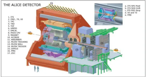
ALICE [43] is a heavy-ion detector which focuses on QCD, designed to address the physics of strongly interacting matter and the quark-gluon plasma at extreme values of energy density and temperature in nucleus-nucleus collisions. It works at a peak luminosity of1027cm−2s−1for nominal Pb-Pb ion operation. Its overall dimensions are16×26×26 m3with a weight of 10000 tons. It consists of a central barrel and a forward muon spectrometer as seen in Figure 2.8. The central part is embedded in a large magnet with a weak solenoid field of 0.5 T.
Figure 2.8:Layout of the ALICE experiment.
From the inside out, it is composed of:
· The Inner Tracking System (ITS), aimed to the secondary vertex reconstruction of charm
and hyperon decays, particle identification and tracking of low-momentum particles. It is formed by six layers of high-resolution detectors in the barrel, made of pixel and silicon drift detectors in the inner layers and silicon micro-strips in the outer ones.
· A cylindrical Time-Projection Chamber (TPC), with a radius covering fromr≈90cm to
r≈250cm. It gives an efficient and robust tracking and it serves for electron identification with momenta up to∼2.5 GeV.
· A large area for particle identification (PID). An array of Time-of-Flight (TOF) counters
measure a momentum range limited to a few times the averagepT(more than97%of all charged particles are belowpT =2 GeV) andπ,K,pseparation better than3σ. A second
system is optimised for the detection of high-pTparticles.
· The electromagnetic calorimeters (PHOS and EMCal), single-arm high-resolution
elec-tromagnetic calorimeters to measure prompt photons,π0andηmesons.
· The forward muon detector, consisting of a complex arrangement of absorbers, a large
dipole magnet (3 T m) and fourteen planes of tracking and triggering chambers located up to 14 m from the interaction point. It is designed to cover the complete spectrum of heavy quark resonances, with a mass resolution sufficient to separate all states.
2.3
ATLAS
The Large Hadron Collider (LHC) at CERN promises a major step forward in the under-standing of the fundamental nature of matter. The ATLAS experiment is a general-purpose de-tector for the LHC, whose design was steered by the need to accommodate the wide spectrum of possible physics signatures covering the exploration of theTeVmass scale where ground-breaking discoveries are expected. Main investigation interests focus on the electroweak sym-metry breaking mechanism and the search for the Higgs boson as well as high-precision mea-surements of the Standard Model parameters and the search for Physics beyond it.
Very small cross sections are expected for many of the interesting processes to be investi-gated. As a result, the LHC is designed to achieve a huge luminosity and consequently a very high interaction rate. The LHC will produce a total rate of109inelastic events per second at de-sign luminosity. This leads to a number of formidable experimental challenges as it implies that, at the design luminosity, about 23 inelastic collisions per bunch crossing on the average will be superimposed on the event of interest. The total proton-proton cross section at √s=14 TeVto
be collected by ATLAS is expected to be roughly 100 mb.
Viewed in this context, these benchmark physics goals can be turned into a set of general requirements for the ATLAS detector.
· The detector requires fast, radiation-hard electronics and sensor elements. At nominal operation, a collision is expected every 25 ns. High-granularity detectors with good time resolution, resulting in low occupancy, can reduce the possible bunch crossings pile-up, avoiding the products of an interaction to be confused with the products of another one. The resulting millions of detector electronic channels require very good synchronisation. · Large acceptance in pseudorapidity with almost full azimuthal angle coverage is required
to achieve the highest hermeticity.
· Good charged-particle momentum resolution and reconstruction efficiency in the inner tracker are essential. Secondary vertices reconstruction in the vertex detectors is needed for offline tagging ofτ-leptons andb-jets and potential long-lived particles predicted by some NP models.
· Very good electromagnetic calorimetry for electron and photon identification and mea-surements, complemented by hadronic calorimetry for accurate jet and missing transverse energy measurements.
· Good muon identification and momentum resolution over a wide range of momenta as well as charge determination.
· Highly efficient triggering is needed to achieve an acceptable event rate.
The ATLAS detector has been designed to be able to identify all kind of particles arising from the proton-proton collisions at the LHC. It is composed of several subdetectors placed in concentric cylinders each of which aims at detecting and reconstructing a particular feature of the particles to be detected. In the following, a brief description of each of the subdetectors is presented. A complete report on the design, construction and performance of the ATLAS detector can be found in Ref. [9].
2.3. ATLAS 17
2.3.1
Inner Detector
The ATLAS Inner Detector (ID) [46] is designed to provide pattern recognition and excellent momentum resolution for charged tracks with pT>0.5 GeVwithin the pseudorapidity1)range
|η| < 2.5. It is the main instrument for the reconstruction and measurement of fermions, b-quark jets and tau-lepton tagging (complementary to that of the calorimeters) and primary and secondary vertices from theppcollisions at the LHC.
The order of 1000 tracks every 25 ns within|η| < 2.5 will need to be reconstructed by the ID at the LHC design luminosity. This induces a very high track and vertex density and hence the necessity for a high-precision measurement in the ID to disentangle each of the tracks and vertices. In order to reconstruct primary vertices, the ID needs to be as close to the interaction point as possible. It surrounds the LHC beam pipe which has a radius of 36 mm.
The ID layout, as shown in Figure 2.9, reflects the performance requirements. The ID is composed of four main parts: two precision tracker detectors made of silicon —the Pixel and the Semi-Conductor Tracker— and the Transition-Radiation Tracker made of straw tubes. In the outer part of the ID there is the central solenoid which immerses the ID in a 2T magnetic field.
Figure 2.9:Layout of the ATLAS Inner Detector.
To maintain an adequate noise performance in the high-radiation environment the ID works in, the silicon sensors must be kept at low temperature, approximately−10◦C. In contrast, the TRT is designed to operate at room temperature. In order to monitor the position of the detector elements, charged tracks are used and, for the SCT, laser interferometric monitoring. The AT-LAS Inner Detector tracking system has been aligned for the analysis of the LHC√s=7 TeV pp
collision data taken during 2010 and 2011. For details on the alignment procedure, see Ref. [47]. The effect of the detector material on object reconstruction is also well understood. For a study on this effect, see Ref. [48].
1)In the right-handed ATLAS coordinate system, the pseudorapidityηis defined asη=−ln[tan(θ/2)], where the polar angleθis measured with respect to the LHC beamline. The azimuthal angleφis measured with respect to thex-axis, which points towards the centre of the LHC ring. Thez-axis is parallel to the anti-clockwise beam viewed from above. Transverse momentum and energy are defined aspT=p sinθandET=E sinθ, respectively.
From the inside out, it is composed of the following subdetectors:
· Pixel Detector
The Pixel [49] is the inner-most subdetector. It is based on silicon sensors and aims at the precision measurements of tracks and vertices at small radii. It has a structure formed by three layers of concentric cylinders in the barrel and three end-cap disks per side perpen-dicular to the beam axis. All pixel modules are identical, with the minimum pixel size on a sensor being50×400µm2. Secondary vertex reconstruction and measurement
perfor-mance is enhanced by the inner-most layer of the pixel system, called ”vertexing layer”, at a radius of about 5 cm.
· Semi-Conductor Tracker
The Semi-Conductor Tracker (SCT) surrounds the Pixel detector. As the pixels, it is based on silicon sensors and aims at the precision measurements of tracks. It has a structure formed by four layers of concentric cylinders in the barrel and nine end-cap disks per side perpendicular to the beam axis. In the barrel region [50], small-angle stereo strips measure R andφcoordinates. Each side of a detector module consists of two6.4cm long, daisy-chained sensors with a strip pitch of80µm. In the end-cap region [51], the detectors have a set of strips running radially and a set of stereo strips. The mean pitch of the strips is also approximately80µm.
The radiation dose has important consequences for the sensors of both Pixel and SCT detectors. The required operating voltage depends on that irradiation.
· Transition Radiation Tracker
The Transition Radiation Tracker (TRT) [52] is next to the SCT and it is devoted to larger radii measurements. It is composed of 4 mm diameter straw tubes filled with a xenon-based gas mixture. In the barrel region the tubes are placed in straw planes parallel to the beam axis. In the end-caps the tubes are arranged radially in wheels in straw planes. The straw hits contribute significantly to the momentum measurements, since the lower precision per point compared to the silicon modules is compensated by the large number of hit measurements and longer measured track length.
· Solenoid
The solenoid extends over a length of5.3m with a diameter of2.5m. and immerses the ID in a2T magnetic field with the function of making the measurement of particle charge and momenta possible.
Details on the subdetectors characteristics can be found in Table 2.1. Table 2.1:Sensitive extension and accuracies of the ID subdetectors.
Pixel SCT TRT
|η|coverage 2.5 2.5 2.0
Barrel End Caps Barrel End Caps Barrel End Caps
Radius (mm) 50.5−122.5 88.8−149.6 299−514 275−560 563−1066 644−1004
Length (mm) 0−400.5 495−650 0−749 839−2735 0−712 839−2710
(R -φ) accuracy (µm) 10 10 17 17 130 per straw tube
zaccuracy (µm) 115 115 (in R) 580 580 (in R) –
2.3. ATLAS 19
2.3.2
Calorimeters
Calorimeters are the main instrument forEmiss
T measurements and for the reconstruction of
a large energy ranged jets, electrons and photons, for which different techniques are required. They need to completely retain electromagnetic and hadronic showers and to prevent hadrons from reaching the muon spectrometer (“punch-through”). A total thickness of 11 interaction lengths (λ) has been shown to be sufficient to reduce punch-through well below the irreducible level of prompt or decay muons. The layout of the Calorimeters is shown in Figure 2.10.
Figure 2.10:Layout of the ATLAS Calorimeters.
· Liquid Argon Electromagnetic Calorimeter
The Liquid Argon (LAr) [53] Electromagnetic Calorimeter is a lead-LAr detector with an accordion structure with kapton electrodes and lead absorber plates. It is divided into a barrel, covering|η| < 1.475and two end-caps, covering1.375 < |η| < 3.2 (although precision measurements are restricted to the range|η| <2.5), each of these parts located in their own cryostat. It shares the vacuum vessel with the solenoid in order to save two vacuum walls. The total thickness of the calorimeter is greater than 22 radiation lengths (X0) in the barrel and greater than24 X0in the end-caps.
For|η|<1.8, a presampler detector is used to correct for the energy lost by electrons and photons upstream of the calorimeter.
· Hadronic Calorimeter
The Hadronic Calorimeter [54] is composed of three main parts:
· The Tile Calorimeter (TileCal), placed directly outside the EM calorimeter envelope,
is a sampling calorimeter using steel as the absorber and scintillating tiles as the active material. It is composed of a barrel covering |η| < 1.0 and a thickness of 1.8
λ and two extended barrels with0.8 < |η| < 1.7 and 3.3λ thick. The total radial extension of the TileCal ranges from an inner radius of 2.28 m to an outer radius of 4.25 m.
· The LAr hadronic end-cap calorimeter (HEC)is located directly behind the Electro-magnetic Calorimeter end-cap, covering the region1.5 <|η|<3.2. It is composed of two independent wheels per end-cap, and it shares the same LAr cryostat as the EM end-caps. Each wheel is divided into two segments in depth, for a total of four layers per end-cap. It covers a radial extension from 0.475 m to 2.03 m.
· The LAr forward calorimeter (FCal)is integrated into the end-cap cryostats,
provid-ing uniformity of the calorimeter coverage and reduced background radiation level in the muon spectrometer, covering the range3.1<|η|<4.9. It is approximately10λ
deep and consists of three modules in each end-cap. The first one, made of cooper, is optimised for electromagnetic measurements. The other two, made of tungsten, are optimised to measure the energy of hadronic interactions.
The approximate10λof active calorimeter combined with the largeηcoverage, provides good resolution for high energy jets and a good measurement of theETmiss.
2.3.3
Muon system
Only a tiny fraction of the LHC collisions that the ATLAS experiment detects, correspond to interesting Standard Model processes and an even smaller fraction may be associated to New Physics. Muons, especially those with high-pTand those that are isolated from other activity in the detector, are much more common in these interesting events than in the background, and thus provide important means to identify such events.
Figure 2.11:Layout of the ATLAS Muon System.
The ATLAS detector has been designed to provide efficient muon identification and precise momentum measurement over a wide range of momentum. The primary detector system built to achieve this objective is the muon spectrometer [55], shown in Figure 2.11. It is based on the magnetic deflection of muon tracks in the large superconducting air-core toroid magnets,
2.3. ATLAS 21 instrumented with separate trigger and high-precision tracking chambers. The muon spectrom-eter comprises three subsystems:
· Superconducting coils
The magnets system [56] provides a toroidal magnetic field whose performance in terms of bending power varies as a function ofη andφ. Each of the three toroids consists of eight coils assembled radially and symmetrically around the beam axis. Over the range
|η|<1.4, magnetic bending is provided by the large barrel toroid, with a bending power of 1.5 to 5.5 T m. For1.6<|η|<2.7, two smaller end-cap magnets inserted into both ends of the barrel toroid give a bending power of 1 to 7.5 T m. Over1.4<|η|<1.6, usually referred to as the transition region, magnetic field is provided by a combination of barrel and end-cap fields. This magnet configuration provides a field which is mostly orthogonal to the muon trajectories and minimises the degradation of resolution due to multiple scattering.
· Precision detectors
These detectors are located in three widely-separated stations at increasing distance from the collision region. In the barrel region, tracks are measured in chambers arranged in three cylindrical layers around the beam axis; in the transition and end-cap regions, the chambers are installed in planes perpendicular to the beam, also in three layers. Over most of theη-range, a precision measurement of the track coordinates in the principal bending direction of the magnetic field is provided by Monitored Drift Tubes (MDT). In the in-nermost plane over2<|η|<2.7, Cathode Strip Chambers (CSC) with higher granularity are used to withstand the demanding rate and background conditions. The measurement precision in each layer is typically better than 100µm. The cathode strip chambers addi-tionally provide a rough (1cm) measurement of theφ-coordinate.
· The trigger system
Resistive Plate Chambers (RPC) in the barrel and Thin Gap Chambers (TGP) in the end-caps provide similarly rough measurements ofηandφ. The trigger chambers for the muon spectrometer provide bunch-crossing identification, well-definedpTthresholds and
mea-sure the muon coordinate in the direction orthogonal to that determined by the precision-tracking chambers.
High-pTmuons typically traverse all three stations obtaining good resolution and efficiency.
2.3.4
Forward detectors
Three smaller detector systems cover the ATLAS very forward region. At±17m from the interaction point lies LUCID (LUminosity measurement using Cerenkov Integrating Detector), detecting inelasticppscattering in the forward direction, and acting as the main online relative-luminosity monitor for ATLAS.
The second detector is the Zero-Degree Calorimeter (ZDC). Located at±140 m from the interaction point, where the LHC beam-pipe is divided into two separate pipes, plays a key role in determining the centrality of heavy-ion collisions.
The third system is ALFA (Absolute Luminosity For ATLAS), located at±240m. It consists of scintillating fibre trackers located inside Roman pots which are designed to approach as close as 1 mm to the beam.
2.3.5
Trigger system
At design luminosity the general-purpose detectors will observe a rate of approximately 1 bunch-crossing (BC) every 25 ns (40 MHz) with an average of 20 interactions per BC. The online event selection process (trigger) must reduce this huge rate of8×108events per second
to a rate of about 4000 events/s for storage and subsequent analysis, rejecting QCD processes while maintaining high efficiency for low cross section interesting physics processes that may include new physics. Decisions must be taken every 25 ns during normal LHC operations at the design luminosity of1034cm−2s−1.
The ATLAS trigger is composed of three levels of event selection (Level 1 [57], Level 2 and Event Filter, referred to as the High Level Trigger or HLT [58] together with the Level 2), each of them refining the decisions made at the previous level.
· Level 1 (L1)is hardware-based. It receives data at the full LHC bunch crossing rate of
40 MHz and uses a limited amount of the total detector information in order to make a decision within2.5µs to reduce the output rate to 75 kHz.
The L1 trigger decision is based on the multiplicities and energy thresholds of electromag-netic clusters, jets and hadronicτ-leptons, missing transverse energy and total transverse energy of L1 objects observed in the trigger towers of the LAr and TileCal sub-systems. The measurement of trajectories in the muon trigger detectors are also used, where the input to the trigger decision is the multiplicity for various muonpTthresholds.
Every L1 trigger configuration can be prescaled by a factorN, where only 1 inNevents is selected and passed to the HLT for further consideration.
· Level 2 (L2)is based on software algorithms. The L1 output is passed to L2 as input to
provide an additional rejection to reduce the output rate from 75 kHz down to 2 kHz. A seed is constructed for each trigger accepted by L1 that consists of a pT threshold and anη−φposition. The L2 algorithms use this seed to construct a region-of-interest (RoI) window around it. The L2 algorithms then use the RoI to selectively analyse the associ-ated fine-grained sub-detector data for thatη−φposition, including reconstructed tracks from the Inner Detector and more optimal calibrations to provide results with improved resolution.
· Event Filter (EF)is also based on software algorithms. The EF receives events accepted by
L2 at a rate of 2 kHz and must provide the additional rejection to reduce the output rate to∼200−400Hz with an event size of approximately1.3Mbyte, compatible with offline computing power and storage capacity. An average processing time of4 sper event is available to achieve this rejection.
Each L2 trigger that has been accepted can be used to seed a sequence of EF algorithms that provide a more refined and complete analysis.
Trigger selections must be adaptable to the changing beam conditions while preserving the interesting physics and satisfying varying detector requirements. As the LHC ramps up to its design luminosity, the use of higher pT thresholds, isolation criteria and tighter selections at HLT become necessary to reduce the background rates while achieving selection of interesting physics with high efficiency, maintaining the output Event Filter rates at about 200 Hz. How-ever, many of the L1 thresholds are retained providing common points of comparison across luminosity regimes.
2.3. ATLAS 23
2.3.6
Object reconstruction in ATLAS
In order to recognise the processes originated in theppcollisions at the LHC and registered by the ATLAS detector, reconstruction and identification is needed for all kinds of particles: electrons and photons, high-pT and isolated muons, tau-leptons decaying to hadrons and jets
in a wide range of pT. High quality and highly efficient reconstruction of all these kinds of
particles is crucial in the searches for new phenomena. A very good measurement of the missing transverse energy,Emiss
T , is also essential for many physics studies in ATLAS.
In the following a basic explanation on how these objects are reconstructed and measured in ATLAS is given for each kind of object. Further details can be found in Ref. [8].
2.3.6.1 Tracking and vertexing
The track and vertex reconstruction is performed mainly in the Inner Detector, where the reconstruction algorithms [59] allow for several processes such as track extrapolation, track fitting including material corrections and vertex fitting and are logically sub-divided into three stages:
1. A pre-processing stage, in which the raw data from the pixel and SCT detectors are
con-verted into clusters, the SCT clusters are transformed into space-points and the TRT raw timing information is translated into calibrated drift circles.
2. A track-finding stage, in which the high granularity of the pixel and SCT detectors is
exploited in order to find prompt tracks originating from the vicinity of the interaction region. This is done in two steps:
First, theinside-out algorithmstarts from 3-point seeds in the silicon detectors (in the three pixel layers and the first SCT layer) and then extends throughout the SCT to form track candidates. Next, these candidates are fitted and extended into the TRT to associate drift-circle information in a road around the extrapolation. Finally, the extended tracks are refitted with the full information of all three detectors. The inside-out algorithm is the baseline algorithm designed for the efficient reconstruction of primary charged particles2)
In a second stage, a complementary track-finding strategy, calledback-tracking, searches for unused track segments in the TRT. Such segments are extended inwards by adding silicon hits. Back-tracking is designed to improve the tracking efficiency for secondaries, which are particles produced in the interactions of primaries, from conversions or decays of long-lived particles.
Finally tracks with a TRT segment but no extension into the silicon detectors are referred to as TRT-standalone tracks.
3. A post-processing stage, in which a dedicated vertex finder is used to reconstruct primary
vertices. These are reconstructed using an iterative vertex finding algorithm [60]. Vertex seeds are obtained from thez-position at the beamline of reconstructed tracks. An iterative
χ2fit is made using the seed and nearby tracks. Tracks displaced by more than7σfrom
the vertex are used to seed a new vertex and the procedure is repeated until no additional vertices can be found. The beam spot position is used as a three-dimensional constraint. During reconstruction, vertices are required to contain at least two tracks, but for the studies in Section 5, vertices are required to have at least five tracks for robustness.
2)Primary particles are defined as particles with a mean lifetime greater than3×10−11sdirectly produced in app interaction or from the subsequent decays or interactions of particles with a lifetime shorter than3×10−11s.
After the track is fitted, corrections at later stages can be applied, like calibration corrections of the pattern recognition, to correct for module deformations or to resolve hit-association am-biguities. This is followed by algorithms dedicated to the reconstruction of photon conversions and of secondary vertices.
2.3.6.2 Electrons and photons
The ATLAS detector must be able to identify efficiently electrons and photons within a large energy range, and to measure their energies with a linearity better than0.5%.
The standard reconstruction of an electromagnetic object is based on clusters reconstructed in the electromagnetic calorimeter and then, the inner detector information determines whether the object is a photon — either converted or unconverted — or an electron. The optimal cluster size depends on the particle type being reconstructed: electrons need larger clusters than pho-tons due to their larger interaction probability in the upstream material and also due to the fact that they bend in the magnetic field.
For each of the reconstructed clusters, algorithms try to find a matching track with momen-tum compatible with the cluster energy. In the case that more than one track matches the same seed cluster, tracks with silicon hits have priority over tracks without silicon hits, the latter tracks being viewed as more likely to belong to electrons originating from photon conversions. For every cluster energy, the reconstruction looks for the presence of an associated conver-sion. An electron candidate is created if a matched track is found and no conversion is flagged. Otherwise, the candidate is classified as a photon. This early classification allows for applying different corrections to electron and photon candidates. It is the starting point of a more refined identification based largely on shower shapes [6,7].
The energy is computed as a weighted average between the cluster energy and the track momentum. Theφandηdirections are taken from the corresponding track parameters unless the track contains no silicon hits, in which case theφposition is taken from the track and theη
is provided by clusterη-pointing.
Three levels of selection are defined for electrons:
1. Loose Electrons. This selection performs a simple electron identification based only on
limited information from the calorimeters. Cuts are applied on the hadronic leakage (ratio ofETin the first layer of the hadronic calorimeter toETof the EM cluster and the ratio of
ET in the hadronic calorimeter to ET of the EM cluster) and on shower-shape variables. This set of cuts provides excellent identification effi