S
WITCHING
F
OR
N
EXT
G
ENERATION
D
ATA
C
ENTER
:
N
EXUS
Gurpreet k. JunejaAbstract:
It has been observed that after years of rapid and often
unplanned expansion, many data centers
containduplicated and under-utilized resources that increase operating costs, power, cooling requirements, and management complexity. With cost control vital tobusiness success, data center managers must find new ways to meet businessrequirements while reducing expenses. Virtualization has the potential todramatically reduce costs and increase data center efficiency by
enablingconsolidation and improving resource
utilization. However, virtualization also placesextensive demands on the network. A fast, reliable switching
infrastructure that isdesigned to provide high
performance in a virtualized environment is critical
tomeeting next-generation data center
requirements.Cisco Nexusswitches offer the latest in
next-generation switching innovations thatenable
efficient virtualization, high-performance computing, and a unified fabric.
Key words:Virtualization, FEX, unified fabric, Virtual Switching System and Virtual Port System.
I.INTRODUCTION
Modern data centers face a wide array of challenges that threaten the integrity of mission critical business applications. These data centers are now stretched to capacity in terms of power, cooling and floor space. Increasing use of server consolidation unified networking and virtualization technologies offer cost savings improved performanceand reliability.So, Cisco Nexus switches offers the next generation switching data centers that helps to create a highly efficient, virtualized data centerby integrating the Cisco Nexus Family of data center-class switches into yournetwork infrastructure.The Cisco Nexus family of Cisco Nexus 7000, Nexus 5000, and Nexus 4000 Seriesdata center switches and Nexus 2000 Series Fabric Extenders (FEX) is designed forhighly scalable, end-to-end 10
Gigabit Ethernet networks. These
data-center-classswitches feature continuous system operations and transport flexibility, and deliverinnovative networking capabilities such as a unified fabric; I/O consolidation; andhigh-performance, low-latency, 10 Gigabit Fibre Channel over Ethernet switching.Together, Cisco Nexus switches can support the extensive bandwidth requirementsthat result from aggregating servers when
you consolidate or virtualized your datacenter network. And by helping to enable scalable server virtualization, the switchesalso help reduce power and cooling costs, and support highly available data centercore and server access.
II.
CISCO
DATA
CENTER
PLAN AND BUILD SERVICES
FOR NEXUS
The Cisco Data Center Plan and Build Services for Nexus help you develop a morescalable, efficient, and resilient data center architecture based on the Cisco Nexushardware platform. They define an architecture that meets your business andtechnical goals, evaluate the gaps between your current infrastructure and yourdesired architecture, and provide recommendations to help you achieve your goals.An important part of this process is integrating your resources to create a more costeffectivesolution that combines the unified fabric, unified computing, applications,storage, and service resources in your network. For example, Cisco experts can helpyou consolidate current server Fibre Channel and Ethernet interfaces into a new 10Gigabit Fibre Channel over Ethernet (FCoE) environment. These services also plana management strategy and transfers knowledge to your server, network, andstorage staffs to help them take full advantage of your data center’s new capabilities.With these advantages, Cisco Data Center Plan and Build Services for Nexus canhelp you create an architecture that supports your organization’s
growth, serverperformance, and storage and
virtualization goals – all while lowering risk
III. EXISTING DATA CENTER
DESIGN
Most existing data centers are deployed according to legacy design data centers. Below figure 1 indicate that the legacy design is a V-shape topology with access and aggregation layers, and with well-known placement of root and secondary root switches, well-known placement of Hot Standby Router Protocol (HSRP) primary and secondary devices, forwarding and blocking links from the access layer to the aggregation layer, and various hardening features in place to
guarantee deterministic spanning-tree behavior upon link failures.
Fig.1 Legacy design data center
IV. NEXT GENERATION DATA CENTER DESIGN The need for a higher level of reliability, with minimized downtime for updates and configuration changes: Once a consolidated architecture is built, it’s critical to keep it up and running with minimum disruption.This can be achieved with the Next Generation Data Centers. The design is shown in the following figure.
Fig.2 Next Generation data center design The need to optimize the use of the data center network infrastructure by moving towards a topology where no link is kept idle, whereas legacy topologies based on Spanning Tree Protocol are known to be inefficient because of Spanning Tree Protocol blocking links or because of active/standby network interface card (NIC) teaming. This need is addressed by Layer 2 multipathing technologies such as Virtual PortChannels (vPCs). The need to optimize computing resources by reducing the rate of growth of physical computing nodes. This need is addressed by server virtualization
using Nexus in Next Generation Data Centers. Various features of this architecture are as follows:
1. This architecture is capable of supporting a SAN and a LAN on the same network (for power use reduction and server consolidation)..
2. There is a need to reduce overall power
consumption in the data center. This need can be addressed with various technologies including unified fabric (which reduce the number of adapters on a given server), server virtualization, and more power-efficient hardware can be achieved by Nexus technology.
3. This architecture provides the ability to distribute Layer 2 traffic on all available links.
4. This architecture provides an intrinsic lower
latency than traditional LAN networks, so that computing cloud can be built on the same LAN infrastructure as regular transactional applications. 5. It has Simplified cabling: For a more efficient
airflow, lower power consumption, and lower cost of deployment of high-bandwidth networks.
6. Reduction of management points: It’s important to
limit the impact of the sprawl of switching points (software switches in the servers, multiple blade switches, and so on).
V.HARDWARE,
SOFTWARE,
ARCHITECTURE AND DESIGN
COMPARISON
OF
NEXT
GENERATION AND LEGACY
DESIGN DATA CENTERS
VSS is used in legacy design data centers while VPC is used in the next generation data centers. The detailed description of VSS is as follows:
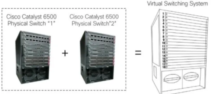
VSS: The Cisco Catalyst 6500 Series Virtual Switching System (VSS) allows the clustering of two or more physical chassis together into a single, logical entity. This technology allows for enhancements in all areas of network design, including high availability, scalability, management, and maintenance.The Virtual Switching System is created by converting two standalone Catalyst 6500 systems to a Virtual Switching System. The conversion is a one-time process that requires a few simple configuration steps and a system reload. Once the individual chassis reload, they are converted into the Virtual Switching System.The Cisco Catalyst 6500 Series Virtual Switching System allows the combination of two switches into a single, logical network entity from the network control plane and management perspectives. It uses Cisco IOS Stateful Switchover (SSO) technology, as well as Non-Stop Forwarding (NSF) extensions to routing protocols, to provide a single, logical switching and routing entity. To neighboring devices, the Cisco Virtual Switching System appears as a single, logical
switch or router. Within the Cisco Virtual Switching System, one chassis is designated as the active virtual switch, and the other is designated as the standby virtual switch. All control plane functions are centrally managed by the active supervisor engine of the active virtual switch chassis. This is shown in the following figure.
Fig. 3 Virtual Switching System The detailed description of VPC is as follows:
VPC:A virtual PortChannel allows links that are
physically connected to two different Cisco Nexus™ 5000 Series devices to appear as a single PortChannel to a third device. The third device can be a Cisco Nexus 2000 Series Fabric Extender or a switch, server, or any other networking device. A VPC can provide Layer 2 multipathing, which allows you to create redundancy by increasing bandwidth, enabling multiple parallel paths between nodes and load-balancing traffic where alternative paths exist.After you enable the VPC function, you create a peer keepalive link, which sends heartbeat messages between the two VPC peer devices.The VPC domain includes both VPC peer devices, the VPC peer keepalive link, the VPC peer link, and all the PortChannels in the VPC domain connected to the downstream device. You can have only one VPC domain ID on each device. VPC provides the following benefits:
1. Allows a single device to use a PortChannel across
two upstream devices.
2. Eliminates Spanning Tree Protocol blocked ports
3. Provides a loop-free topology
4. Uses all available uplink bandwidth
5. Provides fast convergence if either the link or a device fails
6. Provides link-level resiliency 7. Helps ensure high availability
8. The VPC not only allows you to create a
PortChannel from a switch or server that is dual-homed to a pair of Cisco Nexus 5000 Series Switches, but it can also be deployed along with Cisco Nexus 2000 Series Fabric Extenders. Comparison between next generation and legacy design data centers is shown in the following table.
Table 1
Platform Support Cisco Catalyst 6500 Virtual Switching System 1440 Cisco Nexus 7000 and Nexus 5000 Series
Control Plane One single control plane in VSS Separate control planes in VPC In-Service Software Upgrade (ISSU) Across chassis in VSS Within a single system on the Cisco Nexus 7000 Series, there is a mechanism to prevent unwanted VPC configuratio ns during ISSU. Configuration Synchronization
Automatic in VSS Manual, but assisted by protocol verification (Cisco Fabric Services) Number of MCEC Supported Up to 128 port channels per system in standalone mode, and 512 multichassisEtherCh annels in VSS mode The hardware supports 768 virtual PortChannel s. Cisco Discovery Protocol Neighbors
One single neighbor in VSS Each switch appears individually Layer 2 and Layer 3 MCEC Yes in case of VSS VPC is by default a switch port, thus Layer 2
VI.
ADVANTAGES OF NEXT
GENERATION DATA CENTERS
There are various advantages of next generation data centers which overcome the drawbacks of legacy design data centers. Some of them are discussed here.
1. The need for a higher level of reliability, with minimized downtime for updates and configuration changes: Once a consolidated architecture is built, it’s critical to keep it up and running with minimum disruption which cannot be achieved by legacy design data centers.
2. The need to optimize the use of the data center network infrastructure by moving towards a topology where no link is kept idle, whereas legacy topologies based on Spanning Tree Protocol are known to be inefficient because of Spanning Tree
Protocol blocking links or because of
active/standby network interface card (NIC) teaming. This need is addressed by Layer 2
multipathing technologies such as Virtual
PortChannels (vPCs).
3. The need to optimize computing resources by
nodes. This need is addressed by server virtualization.
4. The need to reduce the time that it takes to provision new servers. This need is addressed by the ability to configure server profiles, which can be easily applied to hardware.
5. The need to reduce overall power consumption in the data center. This need can be addressed with various technologies, including unified fabric (which reduce the number of adapters on a given server), server virtualization, and more power-efficient hardware.
6. The need to increase computing power at a lower cost: More and higher-performance computing clouds are being built to provide a competitive edge to various enterprises.
7. Architectures capable of supporting a SAN and a LAN on the same network (for power use reduction and server consolidation):-
Reduce capital and operational expenditures
through more efficient use of equipment.
Lower power and cooling demands by unifying
storage, server and network resources.
Create an architecture that supports your
organization’s growth, server performance, storage and virtualization goals.
Increase business agility with virtual machine.
Maintain business continuity and protect your
existing infrastructure investments.
Speed adoption of your Cisco Nexus solution and help ensure a smooth integration into your operational environment.
VII. DETAILED DESIGN OF
NEXT GENERATION DATA
CENTERS
Generally Next Generation Data Centers comprises of Physical,Access and Aggregation layer.In the Physical layer we used 2K nexus, In Access layer 5K nexus is used and In Aggregation layer 7K is used.
VII. A. CISCO NEXUS 2232TM
10GbE
FABRIC
EXTENDER
(PHYSICAL LAYER)
The Cisco Nexus 2232TM fabric extenders have 32 ports of 1/10GBASE-T and 8 SFP+ ports and behave as remote I/O modules for a parent Cisco Nexus 5000 Series or 7000 Series Switch. The fabric extender, essentially an extension of the Nexus switch fabric, works together with the parent switch to form a distributed modular system. The Cisco Nexus 2232TM forwards all traffic to the parent switch over 10 GbE up-links. Passing all traffic to the parent switch allows traffic to be shaped according to homogeneous policies
established on the parent switch with a single point of management acrossmore than (1,500) 1GbE ports and more than (1000) 10 GbE ports. The distributed modular system architecture includes the following benefits:
• Architectural flexibility • Highly scalable server access • Simplified operations • Increased business benefits
The Nexus 2232TM fabric extender acts as a remote linecard for Servers.
VII. B. CISCO NEXUS 5548P
SWITCH
ARCHITECUTURE
(ACCESS LAYER)
The Cisco Nexus 5548P is a one-rack-unit (1RU), 1 and 10 Gigabit Ethernet and FCoE access-layer switch built to provide 960 Gbps of throughput with very low latency. It has 32 fixed 1 and 10 Gigabit Ethernet ports that acceptmodulesand cables meeting the Small Form-Factor Pluggable Plus (SFP+) form factor. One expansion module slotcan be configured to support up to 16 additional 1 and 10 Gigabit Ethernet ports or 8 Fibre Channel ports plus 8 1and 10 Gigabit Ethernet ports. The switch has a single serial console port and a
single out-of-band 10/100/1000-Mbps Ethernet
management port. Two N+N redundant, hot-pluggable
power supplies and two N+N redundant,
hotpluggablefan modules provide highly reliable front-to-back cooling.All ports are at the rear of the switches, simplifying cabling and reducing cable length. Cooling
is front-toback,supporting hot- and cold-aisle
configurations that help increase cooling efficiency. The front panel includes status indicators and hot swappable, N+N redundant power supplies and their power entry connections andcooling modules. All serviceable components are accessible from the front panel, allowing the switch to be servicedwhile in operation and without disturbing network cabling. This is shown in the following figure.
Cisco Nexus 5000 Series switch located in a switch cabinet either at the end of the row or in the middle of the row.For redundancy the Nexus 5000 Series Switch are generallylocated in two different cabinets. The Nexus 2232TM is uplinkedto the Nexus 5000 switch using Panduit OM3 structured fiber or possibly SFP+ DAC, depending on the location anddistance of the switch. High density and high availability: The Cisco Nexus 5548P provides 48 1/10-Gbps ports in 1RU, and theupcoming Cisco Nexus 5596 Switch provides a density of 96 1/10-Gbps ports in 2RUs. The Cisco Nexus5500 Series is designed with redundant and hot-swappable power and fan modules that can be accessed from the front panel, where status lights offer an at-a-glance view of switch operation. To support efficientdata center hot- and cold-aisle designs, front-to-back cooling is used for consistency with server designs.Various features are discussed below.
1. Single-stage fabric: The crossbar fabric on the Cisco Nexus 5500 Series is implemented as a single-stage fabric, thus eliminating any bottleneck within the switches. Single-stage fabric means that a singlecrossbarfabric scheduler has full visibility into the entire system and can therefore make optimal scheduling decisionswithout building congestion within the switch. With a single-stage fabric, the congestion becomes exclusivelya function of your network design; the switch does not contribute to it.
2. Non blocking line-rate performance: All the 10 Gigabit Ethernet ports on the Cisco Nexus 5500 platform can handle packet flows at wire speed. The absence of resource sharing helps ensure the best performance of each port regardless of the traffic patterns on other ports. The Cisco Nexus 5548P can have 48 Ethernet ports at 10 Gbps sending packets simultaneously without any effect
on performance, offering true 960-Gbps
bidirectional bandwidth. The upcoming Cisco Nexus 5596 can have 96 Ethernet ports at 10 Gbps, offering true 1.92-terabits per second (Tbps) bidirectional bandwidth.
3. Low latency: The cut-through switching
technology used in the application-specific
integrated circuits (ASICs) of the Cisco Nexus 5500 Series enables the product to offer a low latency of 2 microseconds, which remains constant regardless of the size of the packet being switched. This latency was measured on fully configured interfaces, with access control lists (ACLs), quality of service (QoS), and all other data path features turned on. The low latency on the Cisco Nexus 5500 Series together with a dedicated buffer per port and the congestion management features described next make the Cisco Nexus 5500 platform an excellent choicefor latency sensitive environments.
4. Congestion management: Keeping latency low is
not the only critical element for a high-performance
networksolution. Servers tend to generate traffic in bursts, and when too many bursts occur at the same time, a shortperiod of congestion occurs. Depending on how the burst of congestion is smoothed out, the overall networkperformance can be affected. The Cisco Nexus 5500 platform offers a full portfolio of congestionmanagement features to reduce congestion.
VII. C. CISCO NEXUS 7000 and
7010 SERIES
The Cisco Nexus 7000 Series Switch is a modular
switch available in a 10-slot or 18-slot
configuration.The Cisco Nexus 7010 Switch features front-to-back cooling compatible with data center hot-aisle and cold-hot-aisle designs.Cisco Nexus 7000 Series Switches provide high-density 10 Gigabit Ethernet port aggregation. With the 10-slot chassis, the system is capable of an aggregate density of 256 10 Gigabit Ethernet ports, including up to 64 ports of wire-rate 10 Gigabit Ethernet. The current 32-port 10 Gigabit Ethernet modules support 80 gigabits of bandwidth per slot in the system backplane, and offer the choice to operate them in “dedicated” or “shared” mode for eight non-blocking 10 Gigabit Ethernet ports on a single I/O module. Gigabit Ethernet as well as 10 Gigabit Ethernet modules support IEEE 802.1AE MAC security with hardware-based 128-bit Advanced Encryption Standard (AES) encryption. The Cisco Nexus 7000 Series offers control plane virtualization with virtual device contexts (VDCs). The Cisco Nexus 7000 Series supports the ability to forward on all uplinks in typical V-shape or square topologies by using Virtual PortChannel technology. The platform supports up to five hot-swappable, redundant switch fabric modules. This is shown in the following figure.
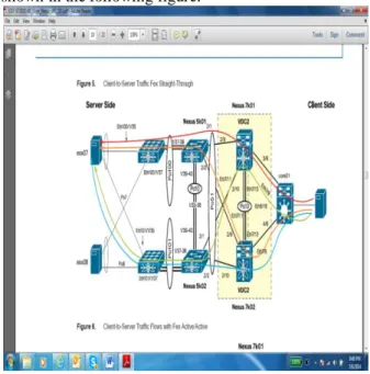
Fig. 5 Example of Client to Server Traffic using Next Generation Data Centre Design
VIII.
CONCLUSION
AND
FUTURE SCOPE
It is concluded that there are two types of switching data center designs: legacy design data center and next generation data center design using nexus. To overcome the drawbacks of legacy design next generation data centers come into existence that provides higher level of reliability, reduce overall power consumption, increase computing power at a lower cost and so on. The future scope of next generation data centers is quite wide in which Cisco Nexus 1000V Series Switches provide a comprehensive and extensible architectural platform for virtualmachine (VM) and cloud networking. The switches are designed to accelerate server virtualization and multitenantcloud deployments in a secure and operationally transparent manner. It is advanced virtual machine networking based on Cisco NX-OS operating system and IEEE 802.1Q switchingtechnology. Cisco vPath technology is used for efficient and optimized integration of virtual network services.
Reference
[1] Cisco Systems, Data Center Design with Cisco Nexus Switches and Virtual PortChannel: Overview, 2010.
[2] Cisco Systems, Cisco Nexus 1000V Series
Switches, 2012.
[3] Panduit, Intel and Cisco, Data Center
Architecture with Panduit, Intel and Cisco, October,2011.
[4] CitRix, Deliver the Next-Generation intelligent Data Center with Cisco Nexus 7000 Series Switches, Citrix Net Scalar Application Delivery Controller, and RISC Technology, 2014.
[5] Cisco White Paper, Energy Efficient Unified
Fabrics: Transform the Data Center
Infrastructure with Cisco Nexus Series, 2009. [6] Bowker M., Your Next Generation Data Center
Starts with Virtualization ,May 2012.
[7] Kendrick S., and Kanning S., Next Generation Data Center, June 2010.
[8] Cisco White Paper, Cisco Nexus 5548P Switch Architecture, 2010.
[9] Cisco White Paper, Cisco Nexus Services, 2011. [10] Cisco White Paper, Cisco Catalyst 6500 Series