Important information
APCI-1500
Please note that the design of the board APCI-1500 has changed! Old design
New design (as of 12/2013)
New design (as of 02/2015)
The function of the board is not affected by this change, i.e. the board remains completely compatible in terms of connector, function and software.
Do you have any questions?
Please find further information
on our website: www.addi-data.com. Do not hesitate to call us or to Front side Back side
Important information
CPCI-1500
Please note that the design of the board CPCI-1500 has changed! Old design
New design
The function of the board is not affected by this change, i.e. the board remains completely compatible in terms of connector, function and software.
Do you have any questions?
Please find further information on our website: www.addi-data.com.
Do not hesitate to call us or to send us an e-mail (see front page for contact data). Front side Back side
DIN EN ISO 9001:2008 certified
ADDI-DATA GmbH
Airpark Business Center
Airport Boulevard B210
77836 Rheinmünster
Germany
Phone: +49 7229 1847–0
Fax: +49 7229 1847–222
E-mail: [email protected]
www.addi-data.com
Technical description
APCI-1500, CPCI-1500
Digital I/O board, optically isolated
Product information
This manual contains the technical installation and important instructions for correct commissioning and usage, as well as production information according to the current status before printing. The content of this manual and the technical product data may be changed without prior notice. ADDI-DATA GmbH reserves the right to make changes to the technical data and the materials included herein.
Warranty and liability
The user is not permitted to make changes to the product beyond the intended use, or to interfere with the product in any other way.
ADDI-DATA shall not be liable for obvious printing and phrasing errors. In addition, ADDI DATA, if legally permissible, shall not be liable for personal injury or damage to materials caused by improper installation and/or commissioning of the product by the user or improper use, for example, if the product is operated despite faulty safety and protection devices, or if notes in the operating
instructions regarding transport, storage, installation, commissioning, operation, thresholds, etc. are not taken into consideration. Liability is further excluded if the operator changes the product or the source code files without authorisation and/or if the operator is guilty of not monitoring the
permanent operational capability of working parts and this has led to damage. Copyright
This manual, which is intended for the operator and its staff only, is protected by copyright. Duplication of the information contained in the operating instructions and of any other product information, or disclosure of this information for use by third parties, is not permitted, unless this right has been granted by the product licence issued. Non-compliance with this could lead to civil and criminal proceedings.
ADDI-DATA software product licence
Please read this licence carefully before using the standard software. The customer is only granted the right to use this software if he/she agrees with the conditions of this licence.
The software must only be used to set up the ADDI-DATA products.
Reproduction of the software is forbidden (except for back-up and for exchange of faulty data carriers). Disassembly, decompilation, decryption and reverse engineering of the software are
forbidden. This licence and the software may be transferred to a third party if this party has acquired a product by purchase, has agreed to all the conditions in this licence contract and the original owner does not keep any copies of the software.
Trademarks
• ADDI-DATA, APCI-1500, MSX-Box and MSX-E are registered trademarks of ADDI-DATA GmbH.
• Turbo Pascal, Delphi, Borland C, Borland C++ are registered trademarks of Borland Software Corporation.
• Microsoft .NET, Microsoft C, Visual C++, MS-DOS, Windows XP, Windows 7, Windows 8, Windows Server 2000, Windows Server 2003, Windows Embedded and Internet Explorer are registered trademarks of Microsoft Corporation.
• LabVIEW, LabWindows/CVI, DASYLab, DIAdem are registered trademarks of National Instruments Corporation.
• CompactPCI is a registered trademark of PCI Industrial Computer Manufacturers Group.
• VxWorks is a registered trademark of Wind River Systems, Inc.
Warning
The following risks result from improper implementation and from use of the board contrary to the regulations:
Personal injury
Damage to the board, the PC and peripherals Pollution of the environment
Protect yourself, others and the environment!
Read the safety precautions (yellow leaflet) carefully!
If this leaflet is not enclosed with the documentation, please contact us and ask for it.
Observe the instructions of the manual!
Make sure that you do not forget or skip any step. We are not liable for damages resulting from a wrong use of the board.
Pay attention to the following symbols:
i
IMPORTANT!
Designates hints and other useful information.
WARNING!
Designates a possibly dangerous situation.
If the instructions are ignored, the board, the PC and/or peripherals may be destroyed.
WARNING!
Designates a possibly dangerous situation.
If the instructions are ignored, the board, the PC and/or
APCI-/CPCI-1500 Contents
WARNING...3
1
DEFINITION OF APPLICATION ...6
1.1 Intended use ... 6 1.2 Usage restrictions... 6 1.3 Limits of use... 71.4 General description of the board ... 7
2
USER ...8
2.1 Qualification ... 8
2.2 Country-specific regulations ... 8
3
HANDLING OF THE BOARD...9
4
TECHNICAL DATA ...10
4.1 Electromagnetic compatibility (EMC) ... 10
4.2 Physical set-up of the board... 10
4.3 Options ... 10
4.4 Limit values... 11
5
INSTALLATION OF THE BOARD ...14
5.1 APCI-1500... 14
5.1.1 Opening the PC...14
5.1.2 Selecting a free slot ...14
5.1.3 Inserting the board...15
5.1.4 Closing the PC ...15
5.2 CPCI-1500 ... 16
5.2.1 Opening the PC...16
5.2.2 Selecting a free slot ...16
5.2.3 Inserting the board...17
6
DRIVER INSTALLATION ...18
6.1 Questions and software download from the Internet... 18
7
CONNECTING THE PERIPHERALS...19
7.1 Pin assignment... 19
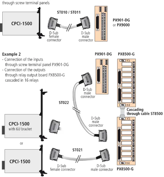
7.2 Connection principle ... 20
7.3 Connection examples... 20
APCI-/CPCI-1500 Contents
8.1 Block diagram... 23
8.2 Description of the board ... 24
8.3 Functions ... 24
8.3.1 Digital inputs ... 24
Special input functions of the digital inputs ... 25
1) Interrupt logic of the digital inputs 1-14 ... 25
2) Counter... 27 8.3.2 Digital outputs... 27 Special functions ... 28 8.3.3 Interrupt ... 29 8.3.4 Counter/timer ... 30 Frequencies... 31 Data ... 31
Option (only implemented for the APCI-1500) ... 31
9
STANDARD SOFTWARE ...32
10
RETURN OR DISPOSAL ...33
10.1 Return ... 33
10.2 Disposal of ADDI-DATA waste equipment... 34
11
GLOSSARY...35
12
INDEX ...38
Figures
Fig. 3-1: Correct handling of the APCI-1500 ... 9Fig. 3-2: Correct handling of the CPCI-1500... 9
Fig. 5-1: PCI slot types ... 14
Fig. 5-2: Inserting the board ... 15
Fig. 5-3: Fastening the board at the back cover ... 15
Fig. 5-4: CPCI slot types... 16
Fig. 5-5: Slot: Insert the board... 17
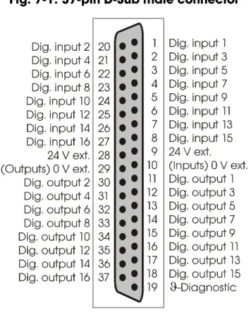
Fig. 7-1: 37-pin D-Sub male connector... 19
Fig. 7-2: Connection principle of the input and output channels ... 20
Fig. 7-3: Connection examples for the input and output channels ... 20
Fig. 7-4: APCI-1500: Connection to the screw terminal panel ... 21
Fig. 7-5: CPCI-1500: Connection to the screw terminal panel... 22
Fig. 8-1: Block diagram of the APCI-1500 ... 23
Fig. 8-2: Block diagram of the CPCI-1500... 23
Fig. 8-3: Interrupt logic – Digital inputs 1-8... 26
Fig. 8-4: Protection circuitry for the inputs... 27
Definition of Application APCI-/CPCI-1500
1
DEFINITION OF APPLICATION
1.1
Intended use
The APCI-1500 board must be inserted in a PC withPCI slots which is used as
electrical equipment for measurement, control and laboratory pursuant to the norm EN 61010-1 (IEC 61010-1).
The used personal computer (PC) must fulfil the requirements of IEC 60950-1 or EN 60950-1 and EN 55022 or IEC/CISPR 22 and EN 55024 or IEC/CISPR 24. The use of the board APCI-1500 in combination with external screw terminal
panels requires correct installation according to IEC 60439-1 or EN 60439-1 (switch cabinet / switch box).
The CPCI-1500 board must be inserted in a CompactPCI/PXI computer with
CompactPCI slots which is used as electrical equipment for measurement, control and laboratory pursuant to the norm EN 61010-1
(IEC 61010-1).
The used personal computer (PC) must fulfil the requirements of IEC 60950-1 or EN 60950-1 and EN 55022 or IEC/CISPR 22 and EN 55024 or IEC/CISPR 24. The use of the board CPCI-1500 in combination with external screw terminal
panels requires correct installation according to IEC 60439-1 or EN 60439-1 (switch cabinet / switch box).
1.2
Usage restrictions
The APCI-/CPCI-1500 board must not be used as safety related part (SRP).
The board must not be used for safety related functions, for example for emergency stop functions.
The APCI-/CPCI-1500 board must not be used in potentially explosive
atmospheres.
The APCI-/CPCI-1500 board must not be used as electrical equipment according
APCI-/CPCI-1500 Definition of Application
1.3
Limits of use
All safety information and the instructions in the manual must be followed to ensure proper intended use.
Uses of the board beyond these specifications are considered as improper use. The manufacturer is not liable for damages resulting from improper use. The board must remain in its anti-static packaging until it is installed.
Please do not delete the identification numbers of the board or the warranty claim will be invalid.
1.4
General description of the board
Data exchange between the APCI-/CPCI-1500 board and the peripheral is to
occur through a shielded cable. This cable must be connected to the 37-pin D-Sub male connector of the APCI-/CPCI-1500 board
The board has 16 input channels and 16 output channels for processing digital 24 V signals. An external 24 V supply voltage is necessary to run the output channels. The screw terminal panel PX901-DG and the relay board PX8500 allow connecting
the 24 V supply voltage through a shielded cable
The connection with our standard cable ST010 complies with the following
specifications:
- metallised plastic hoods - shielded cable
User APCI-/CPCI-1500
2
USER
2.1
Qualification
Only persons trained in electronics are entitled to perform the following works:
- installation - commissioning - use
- maintenance.
2.2
Country-specific regulations
Do observe the country-specific regulations regarding
- the prevention of accidents
- electrical and mechanical installations - Electromagnetic compatibility (EMC).
APCI-/CPCI-1500 Handling of the board
3
HANDLING OF THE BOARD
Fig. 3-1: Correct handling of the APCI-1500
Hold the board cautiously at the outer end and at the slot bracket. Do not touch the surface of the board!
Fig. 3-2: Correct handling of the CPCI-1500
Hold the board cautiously at the outer end and at the front panel. Do not touch the surface of the board!
Technical data APCI-/CPCI-1500
4
TECHNICAL DATA
4.1
Electromagnetic compatibility (EMC)
The board APCI-/CPCI-1500 is suited for installation in personal computers
(PCs) which comply with the European EMC directive.
The board APCI-/CPCI-1500 complies with the European EMC directive.
The tests were carried out by a certified EMC laboratory in accordance with the norm from the EN 61326 series (IEC 61326). The limit values as set out by the European EMC directive for an industrial environment are complied with. The respective EMC test report is available on request.
4.2
Physical set-up of the board
APCI-1500 CPCI-1500
Dimensions
160 x 100 mm 131 x 100 mm
Weight 160 g 200 g
Installation PCI 3.3V/5V (32-bit) slot or PCI 3.3V/5V (64-bit) slot
CompactPCI 3.3V/5V (32-bit) slot or CompactPCI 3.3V/5V (64-bit) slot Connection to the
peripheral
37-pin D-Sub male connector 37-pin D-Sub male connector
i
IMPORTANT!
The connection lines must be installed in such a way that they
are protected against mechanical loads.
4.3
Options
The board APCI-1500 is available in 2 versions:
- APCI-1500: 24 V inputs
APCI-/CPCI-1500 Technical data
Option for the CPCI-1500:
URS-1500-6U: 6U front panel for mounting in 6U housing
4.4
Limit values
Max. height: ... 2000 m above NN Operating temperature:... 0 to 60°C
Storage temperature: ... -25 to + 70°C
Relative humidity at indoor installation
50% at +40 °C 80% at +31 °C
Minimum PC requirements (APCI-1500):
- PCI BIOS
- operating system: Windows 8/7/XP, Linux - bus speed: ... < 33 MHz
Minimum system requirements (CPCI-1500):
- 32-/64-bit CompactPCI bus (3.3 V / 5 V)
- PCI BIOS, PCI 2.1 specification and complyingwith CompactPCI 2.1
- operating system ...Windows 8/7/XP, Linux - bus speed...≤ 33 MHz
Energy requirements
- operating voltage of the PC: ... 5 V ± 5%
- current consumption in mA (without load): typ. See table ± 10%
APCI-1500 CPCI-1500
+5 V of the PC 400 mA 220 mA
Ext. +24 V - 10 mA
24 V digital input channels
Input type: ... common ground according to IEC1131-2
Number of inputs: ... 16
Interruptible inputs: ... 14 (inputs 1-14) Nominal voltage: ... 24 VDC
Input current at nominal voltage: ...
APCI-1500:... 6 mA
CPCI-1500:...inputs 1-4: 6.6 mA
Technical data APCI-/CPCI-1500
Logic input levels: ... UH1) max.: 30 V
UH min.: 19 V
UL2)max.: 14 V
UL min.: 0 V
Maximum input frequency: ... 5 kHz (at nominal voltage)
12 V digital input channels (APCI-1500-12 V)
Input type: ... mass related inputs Number of inputs: ... 16
Interruptible inputs: ... 14 (inputs 1-14) Nominal voltage: ... 12 VDC
Input current at nominal voltage: ... 4.2 mA
Logic input levels: ... UH max.: 16 V / 6.3 mA typ.
UH min.: 9 V / 2.7 mA typ.
UL max.: 6 V / 1.2 mA typ.
UL min.: 0 V
Maximum input frequency: ... 5 kHz (at nominal voltage)
24 V digital output channels APCI-1500:
Output type: ... high-side (load to ground according to ... IEC1131-2)
Number of outputs: ... 16 Nominal voltage: ... 24 VDC
Optical isolation: ... 1000 V (via opto-couplers) Supply voltage: ... 10-36 V
Current limit: ... 3 A (all 16 channels, via PTC) Output current per output: ... 500 mA max.
Short-circuit current per output: ... 1.5 A max. (pulse current) ... shutdown logic at 24 V ... RLoad = 0.1 Ω
RDS ON resistance: ... 0.4 Ω max.
Overtemperature (shutdown): ……… 170 °C typ. (output driver) Temperature hysteresis: ... 20 °C typ. (output driver) Start-up time: ... 100 μs typ.
Shutdown time: ... 60 µs typ.
CPCI-1500:
Output type: ... high-side (load to ground according to ... IEC1131-2)
Number of outputs: ... 16 Nominal voltage: ... 24 VDC
Optical isolation: ... 1000 V (via opto-couplers)
APCI-/CPCI-1500 Technical data
Supply voltage: ... 11-36 V
Current limit: ... 1.85 A (per 8 channels, via PTC) Output current per output: ... 500 mA max.
Short-circuit current per output: ... 1.7 A max. (pulse current) ... shutdown logic at 24 V ... RLoad = 10 mΩ
RDS ON resistance: ... 150 mΩ typ.
Overtemperature (shutdown): ……… 130 °C (output driver) Temperature hysteresis: ... 15 °C (output driver) Start-up time: ... 40 μs typ.
Shutdown time: ... 470 µs typ.
Interruptible diagnosis, read back through status bit
ϑ-diagnosis: ... Pin 19 (24V/10 mA) is
switched on in case of overload of the outputs or overtemperature Vcc-diagnosis: ... is switched on in case of voltage
drop < 5 V
Safety
Optical isolation
(DIN VDE 0411-100): ... 1000 V (from the PC to the external peripheral).
Logic: ... positive Shut down logic: See ϑ-diagnostic
Watchdog: ... resets all the output channels, if no software trigger has happened. Times
from 10 μs to 37 s are available. Counter/Timer input channels: ... max. 10 kHz, 24 V
APCI-1500 option:
Fast counter/timer input channels: ... max. 140 kHz, 24 V
CPCI-1500
Status LEDs on front connector:
Green LED lights: ... ext. voltage supply > 8 V Red LED flashes: ... error signal from the outputs
Installation of the board APCI-/CPCI-1500
5
INSTALLATION OF THE BOARD
i
IMPORTANT!
Do observe the safety precautions (yellow leaflet)!
5.1
APCI-1500
5.1.1
Opening the PC
♦ Switch off your PC and all the units connected to the PC
♦ Pull the PC mains plug from the socket.
♦ Open your PC as described in the manual of the PC manufacturer.
5.1.2
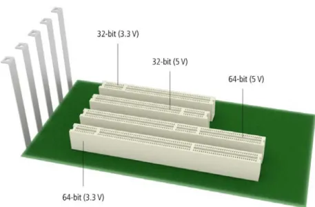
Selecting a free slot
♦ Insert the board in a free 32-bit PCI slot (5 V or 3.3 V).
Fig. 5-1: PCI slot types
♦Remove the back cover of the selected slot according to the instructions of the PC manufacturer. Keep the back cover. You will need it if you remove the board
♦Discharge yourself from electrostatic charges.
APCI-/CPCI-1500 Installation of the board
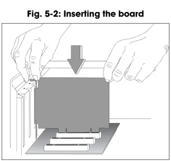
5.1.3
Inserting the board
♦ Insert the board vertically into the chosen slot.
Fig. 5-2: Inserting the board
♦ Fasten the board to the rear of the PC housing with the screw which was fixed on the back cover.
Fig. 5-3: Fastening the board at the back cover
♦ Tighten all loose screws.
5.1.4
Closing the PC
Installation of the board APCI-/CPCI-1500
5.2
CPCI-1500
5.2.1
Opening the PC
♦ Switch off the CompactPCI system and all units connected to the CompactPCI system.
♦ Pull the mains plug of the CompactPCI system from the socket.
♦ Remove the front cover from a free CompactPCI slot.
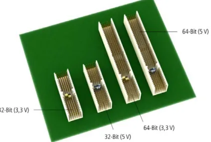
5.2.2
Selecting a free slot
♦ Select a free 32-/64-bit CPCI slot (5 V or 3.3 V) for the board.
Fig. 5-4: CPCI slot types
♦ Please provide for potential equalisation.
APCI-/CPCI-1500 Installation of the board
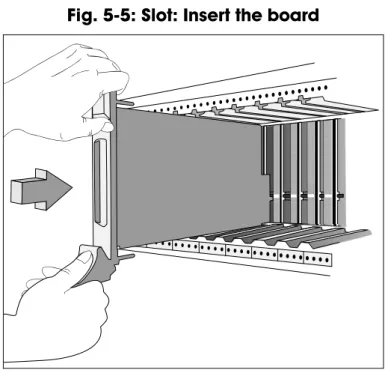
5.2.3
Inserting the board
♦ Insert the board into the guiding rails of the rack and push it forward to the rear of the housing.
In order to plug it in, a slight resistance has to be overcome.
Fig. 5-5: Slot: Insert the board
♦ If there is a screw at the front panel of the board, fasten the board at the upper part of the housing with it.
i
IMPORTANT!
To pull the board out of the rack, the fold-away handle (if available)
at the board front panel has to be pushed slightly upwards.
Driver installation APCI-/CPCI-1500
6
DRIVER INSTALLATION
In the document “Quick installation PC boards” (see PDF link), you can get information on the selection of the appropriate driver and on the driver download. The most important information on the installation of drivers of the type
“ADDI-DATA Multiarchitecture Device Drivers 32-/64-Bit for x86/AMD64” as well as on the installation of the corresponding samples is to be found in the installation instructions (see PDF link).
6.1
Questions and software download from the Internet
Do not hesitate to e-mail us your questions:
Free downloads of standard software
You can download the latest version of the software for the board
APCI-/CPCI-1500 from our website:www.addi-data.com
i
IMPORTANT!
Before using the board or in case of malfunction during
operation, check if there is an update available on our website
(technical description, drivers) or contact us directly.
APCI-/CPCI-1500 Connecting the peripherals
7
CONNECTING THE PERIPHERALS
WARNING!
Interferences are emitted and spread through the connection cables.
Therefore, a wrong cable might endanger the operating and functional safety
of your system.
7.1
Pin assignment
Connecting the peripherals APCI-/CPCI-1500
7.2
Connection principle
Fig. 7-2: Connection principle of the input and output channels
7.3
Connection examples
APCI-/CPCI-1500 Connecting the peripherals Fig. 7-4: APCI-1500: Connection to the screw terminal panel
Connecting the peripherals APCI-/CPCI-1500 Fig. 7-5: CPCI-1500: Connection to the screw terminal panel
APCI-/CPCI-1500 Functions of the board
8
FUNCTIONS OF THE BOARD
8.1
Block diagram
Fig. 8-1: Block diagram of the APCI-1500
Functions of the board APCI-/CPCI-1500
8.2
Description of the board
The board APCI-/CPCI-1500 is intended for parallel input/output for digital
signals in 24 V industrial environments. The peripheral and the system have a simultaneous optical isolation.
The board offers:
- 16 digital inputs: 14 are interruptible.
- 3 counters (or timers): programmable by software
- 1 timer: can be used as a watchdog for the outputs.
- 16 digital outputs:
- short-circuit protection relating to GND - protection against overtemperature - small ON resistor
- wide supply voltage range
- the outputs are switched off if the voltage drops below the limit value (5 V). The base address and the interrupt lines are automatically set through the BIOS. 16-bit data bus switchable to 8-bit data bus.
EMC: design in accordance with CE regulations.
8.3
Functions
8.3.1
Digital inputs
The board APCI-/CPCI-1500 has 16 inputs (24 V), which are optically isolated.
14 inputs are interruptible.
The inputs acquire the status of external signals: the input information is stored through software as a value in the memory cell of the PC. This value is converted to give the status of the input signals. (> 17 V or not)
All inputs have a common current ground:
0V Ext. (inputs), pin 10 of the 37-pin D-Sub male connector.
The current input is at 6 mA with a nominal voltage of 24 V. The maximum input voltage is 30 V.
Logic "1" corresponds to an input voltage > 19 V Logic "0" corresponds to an input voltage < 14 V.
i
IMPORTANT!
If you operate all inputs with the same voltage supply,
the voltage supply
APCI-/CPCI-1500 Functions of the board
Transil diodes, Z diodes, C filters and optical couplers protect the system bus from noise emitted by the peripheral. The effects of inductive and capacitive noise are thus reduced.
The board requires no initialisation to read the 24 V digital information. After successful power ON reset, data is immediately available on the board.
Special input functions of the digital inputs
1) Interrupt logic of the digital inputs 1-14
The inputs 1 to 14 can generate an interrupt. With a logic AND- or OR-functions of the inputs, the condition (=event) is defined in order to generate an interrupt. At the AND-logic the conditions (=events) for generating an interrupt must be available at the same time.
The AND-function is limited to the inputs 1-8 (port 1).
Should you use events, do observe that the AND-logic cannot be used on Port 2.
At the OR-logic one event is sufficient for generating an interrupt.
The OR-logic can be used on all inputs (port 1 and port 2). Port 2 has only 6 inputs.
The definition for the event, which can generate an interrupt, is defined through the event mask. See software function [i_APCI1500_SetInputEventMask (…)]. Digital inputs, which shall not influence the interrupt generation, will be masked out.
At the AND-logic a low-level (typ. 0 V), a high-level (typ. 24 V), a falling edge (signal switching from 24 V to 0 V) and/or a rising edge (signal switching from 0 V to 24 V) can be defined. Max. one edge switching can be defined.
„X“: The input is not used for the event „0“: The input must be on „0“ (typ. 0 V) „1“: The input must be on „1“ (typ. 24 V) „2“: The input reacts to a falling edge
(signal switching from 24 V to 0 V) „3“: The input reacts to a rising edge
(signal switching from 0 V to 24 V) „4“: The input reacts to both edges
Functions of the board APCI-/CPCI-1500
Example: Port 1 (digital inputs 1-8), AND-logic
Event for generating an interrupt:
Digital input 8 7 6 5 4 3 2 1 Event mask 3 X 1 0 0 1 0 1 The following events generate an interrupt:
Inputs 2 and 4 and 5 = 0 V Inputs 1 and 3 and 6 = 24 V Input 8 = rising edge
Input 7: No meaning
Fig. 8-3: Interrupt logic – Digital inputs 1-8
Example: Port 1 (digital inputs 1-8), OR logic
Event for generating an interrupt:
Digital input 8 7 6 5 4 3 2 1 Event mask X X X X 0 0 1 1 The inputs 5-8 have no meaning.
An interrupt will be generated if a voltage of 24 V will be connected to input 1 or input 2.
Please note: The OR-event if fulfilled as long as at least one of the two inputs is
APCI-/CPCI-1500 Functions of the board
The meaning in this case is:
- If input 1 switches to 24 V and input 2 stays on 0 V, an interrupt will be generated
- If input 2 switches from 0 v to 24 V, while input 1 stays on 24 V, no interrupt will be generated because the OR event is not fulfilled
2) Counter
Counter 1: Input 14 signal input
Counter 2: Input 10 signal input
Input 11 can be used for a "trigger" function
Input 12 can be used for a "gate" function.
Counter 3 Input 15 signal input
Input 16 can be used as a "gate" function
Fig. 8-4: Protection circuitry for the inputs
8.3.2
Digital outputs
The board has 16 optically isolated outputs. The outputs comply with the 24 V industry standard (IEC1131-2):
Positive logic is used
- logic "1": sets the output through software (switch on ON), - logic "0": resets the output (switch on OFF).
The outputs switch the +24Vext. outside to the load. One end of the load is
connected with the ground of 0V EXT (outputs). All outputs have a common ground: 0V ext. (outputs) pin 29 of the 37-pin D-Sub male connector.
Functions of the board APCI-/CPCI-1500
i
IMPORTANT!
If you use all outputs with the same voltage supply,
the voltage supply
must deliver at least the power required for your application.
The maximum supply voltage is 36 V. Each output can switch 500 mA current. But the current is limited for all the outputs on approx. 3 A by a self-resetting fuse.
Features of the outputs:
- Short-circuit protection relating to GND. The output is switched off.
- Protection against overtemperature: shut down logic. Each group of 4 outputs is switched off: 1 to 4, 5 to 8, 9 to 12, 13 to 16.
- The outputs are switched off if the ext. supply voltage drops below 5 V. - Diagnostic report through status register or interrupt to the PC in case of short-circuit, overtemperature, voltage drop or watchdog.
Transil diodes, C filters and optical couplers filter noise from the peripheral to the system bus. Thus the effects of inductive and capacitive noise are reduced.
Possible noise emissions are also reduced by C filters.
The board requires no initialisation to output the 24V digital information. You can program the outputs immediately after successful power ON reset
State after power ON reset: all the outputs are reset (switch on OFF).
Special functions
2 diagnostic bits are available on the board.
The ϑ-diagnostic (Pin 19 on the front connector) is released: - when short-circuit has occurred on an output or
- in case of overtemperature on an output component (8 channels). The Vcc-diagnostic informs that:
- the external voltage supply has dropped < 5 V.
These error data are available through an interrupt routine. See API functions: i_APCI1500_SetBoardIntRoutineXX, i_APCI1500_ResetBoardIntRoutine.
APCI-/CPCI-1500 Functions of the board Fig. 8-5: Protection circuitry for the outputs
8.3.3
Interrupt
The board has an interrupt line. An interrupt line of the PCI bus is allocated to the board through the BIOS.
Possible interrupt sources:
- Event 1 has occurred (input 1-8), - Event 2 has occurred (input 9-14), - Counter/Timer 1 has run down - Counter/Timer 2 has run down - Counter/Timer 3 has run down
- Watchdog has run down, the outputs are reset,
- Voltage error (the external voltage supply has dropped below 5 V), - Short-circuit error, overtemperature error.
The interrupt source information are available on the user program through an interrupt routine
See API functions: i_APCI1500_SetBoardIntRoutineXX,
i_APCI1500_ResetBoardIntRoutine. An event indicates a change of status (level):
- on an input (ex. "0"Æ1")
Functions of the board APCI-/CPCI-1500
8.3.4
Counter/timer
On the board three 16-bit counters/timers are available in the component Z8536 (downwards counting). Each counter/timer can be programmed by software. If the component Z8536 operates as a counter, the corresponding inputs are used as follows:
Counter
Counter 1: Input 14 signal input.
Counter 2: Input 10 signal input
Input 11 can be used as a "trigger" function
Input 12 can be used as a "gate" function.
Counter 3 Input 15 signal input
Input 16 can be used as a "gate" function.
Timer
If the component Z8536 is used as a timer, the frequency is used as a reference. "Gate" and "trigger" are possible through the inputs.
Gate: can be driven by software or an input can be set. The polarity of the input
can be programmed. This "gate" stops counting when it is set.
Trigger: can be driven by software or an input can be set.
The polarity of the input can be programmed. This "trigger" re-loads the counter/timer with the initial counter value.
The following functionalities are available:
- Initialising the counters/timers, - Starting the counters/timers, - Stopping the counters/timers,
- Reading the counter value of the counters/timers
The counter/timer 3 has a special function: Watchdog/Timer.
The function Watchdog/Timer allows to supervise the software or PC.
The principle is:
The counter/timer 3 is programmed as a non reloadable timer.
The timer is started. The outputs are reset when the timer has run down (switch OFF).
The user software must be built in such a way that the output channels are always set to "ON" again.You thus avoid that the watchdog runs down.
APCI-/CPCI-1500 Functions of the board Frequencies
The input frequency for the timer is selected through the software function i_APCI1500_InitTimerInputClock (...) Available frequencies: 111.86 kHz ± 100 ppm, 3.49 kHz ± 100 ppm 1.747 kHz ± 100 ppm.
i
IMPORTANT!
The timer component internally operates with
half of the input frequency
.
Data
Approximate watchdog times: Input frequency 17.9 µs Æ 1175 ms 111.86 kHz 574 µs Æ 37.65 s 3.49 kHz 1.14 ms Æ 74.9 s 1.747 kHz
Option (only implemented for the APCI-1500)
The counter input channels 1, 2 and 3 can be equipped with fast optical couplers. The maximum input frequency is then 140 kHz. (Standard frequency: 10 kHz)
Standard software APCI-/CPCI-1500
9
STANDARD SOFTWARE
The API software functions supported by the board are listed in an HTML document. A description on how to access the respective file can be found in the document “Quick installation PC boards” (see PDF link), in the chapter “Standard software”.
Return or disposal APCI-/CPCI-1500
10
RETURN OR DISPOSAL
10.1
Return
If you need to return your board, you should read the following checklist before.
Checklist for returning the board:
• Specify the reason for returning your board (e.g. exchange, modification, repair), the serial number of the board, the contact person in your company including his/her telephone extension and e-mail address, as well as the mailing address for a potential new delivery.
You do not have to indicate the RMA number.
Fig. 10-1: Serial number
• Note down the serial number of the board.
• Place the board in an ESD protective cover. Then pack it in a cardboard box so that it is well-protected for shipping. Send the packed board together with your details to:
ADDI-DATA GmbH Airpark Business Center Airport Boulevard B210 77836 Rheinmünster Germany
• If you have any questions, do not hesitate to contact us: Phone: +49 7229 1847-0
Return or disposal APCI-/CPCI-1500
10.2
Disposal of ADDI-DATA waste equipment
ADDI-DATA organises the disposal of ADDI-DATA products that were put on the German market after 13 August 2005.
If you want to return waste equipment, please e-mail your request to: [email protected]. Boards that were delivered after 13 August 2005 can be recognised by the following label:
Fig. 10-2: Disposal: Label
This symbol indicates the disposal of waste electrical and electronic equipment. It is valid in the European Union and in other European countries that have a separate collection system. Products carrying this symbol must not be treated as household waste.
For more detailed information on the recycling of these products, please contact your local citizens’ office, your household waste collection service, the shop where you bought this product or the distributor you purchased this product from.
If you dispose of this product correctly, you will help to prevent damage that could be caused to the environment and to human health by inappropriate disposal. The recycling of materials will help to conserve our natural resources.
Disposal in other countries than Germany
Glossary APCI-/CPCI-1500
11
GLOSSARY
Table 11-1: Glossary
Term
Description
A/D converter = ADC
An electronic device that produces a digital output directly proportional to an analog signal output.
Acquisition The process by which data is gathered by the computer for analysis or storage.
Bus The group of conductors that interconnect individual circuitry in a computer. Typically, a bus is the expansion vehicle to which I/O or other devices are connected. Examples of PC buses are PCI, PC Card (PCMCIA), ISA (AT), and EISA bus. Clock A circuit that generates time and clock pulses for the
synchronisation of the conversion
Counter A circuit that counts pulses or measures pulse duration
Creeping distance In order to avoid the danger of the effects of electrical voltages and currents for electrical-mechanical components, it is
required to keep minimum isolation distances. The creeping distance is the shortest distance alongside of an isolation surface between two reference points (contact elements). D/A converter = DAC
A device that converts digital information into a corresponding analog voltage or current.
Data acquisition Gathering information from sources such as sensors and transducers in an accurate, timely and organized manner. Modern systems convert this information to digital data which can be stored and processed by a computer.
Diagnostic program A utility program used to isolate hardware malfunctions on-board, or software malfunctions in the program.
DC voltage = Direct current voltage
DC voltage means that the voltage is constant respecting the time. It will always fluctuate slightly. Especially at switching on and switching off the transition behaviour is of high significance.
Digital signal A signal which has distinct states. Digital computers process data as binary information having either 1 or 0 states.
Driver A part of the software that is used to control a specific
hardware device such as a data acquisition board or a printer. FIFO = First In First Out
The first data into the buffer is the first data out of the buffer. Gain The factor by which an incoming signal is multiplied. Ground A common reference point for an electrical system.
Impedance The reciprocal of admittance. Admittance is the complex ratio of the voltage across divided by the current flowing through a device, circuit element, or network.
Glossary APCI-/CPCI-1500
Term
Description
Inductive loads The voltage over the inductor is U=L.(dI/dt), whereas L is the inductivity and I is the current. If the current is switched on fast, the voltage over the load can become very highly for a short time.
Input impedance The measured resistance and capacitance between the high and low inputs of a circuit.
Input level The input level is the logarithmic relation of two electric units of the same type (voltage, current or power) at the signal input of any receive device. The receive device is often a logic level that refers to the input of the switch. The input voltage that corresponds with logic “0” is here between 0 and 15 V, and the one that corresponds with logic “1” is between 17 and 30 V. Interrupt A signal to the CPU indicating that the board detected the
occurrence of a specified condition or event.
Limit value Exceeding the limit values, even for just a short time, can lead to the destruction or to a loss of functionality.
MUX = Multiplexer
An array of semiconductor or electromechanical switches with a common output used for selecting one of a number of input signals.
Noise immunity Noise immunity is the ability of a device to work during an electromagnetic interference without reduced functions. Noise suppression The suppression of undesirable electrical interferences to a
signal. Sources of noise include the ac power line, motors, generators, transformers, fluorescent lights, CRT displays, computers, electrical storms, welders, radio transmitters, and others.
Operating voltage The operating voltage is the voltage that occurs during the continuous operation of the device. It may not exceed the continuous limit voltage. Furthermore, any negative operation situations, such as net overvoltages over one minute at
switching on the device must be taken in consideration.
Optical isolation The technique of using an optoelectric transmitter and receiver to transfer data without electrical continuity, to eliminate high-potential differences and transients.
Opto-coupler With an opto-coupler direct current voltage can be transferred. The advantage is the small size.
Output current The maximum amount of current the sensor can supply across the output signal, expressed as amps DC (A DC).
Output voltage The nominal voltage output reading when shaft is rotated to full range, expressed in volts DC /Vo DC)
Parameter The parameters of a control comprise all fort he control process required numeric values, e.g. for limit values and technological number.
PCI bus PCI bus is a fast local bus with a clock rate up to 33 MHz. This bus is used for processing a great number of data. The PCI bus is not limited like the ISA and EISA systems.
Glossary APCI-/CPCI-1500
Term
Description
Protective circuitry A protective circuitry of the active part is done in order to protect the control electronic. The simplest protective circuitry is the parallel switching of a resistance.
Reference voltage Reference voltages are stable voltages that are used as reference unit. From them voltages can be derived that are required for example in current supplies and in other electronic circuitries.
Resolution The smallest significant number to which a measurement can be determined. For example a converter with 12-bit resolution can resolve 1 part in 4096.
Settling time The time required, after application of a step input signal, for the output voltage to settle and remain within a specified error band around the final value. The settling time of a system includes that of all of the components of the system.
Short circuit A short circuit of two clamps of an electric switch is when the concerning clamp voltage is zero.
Short circuit current Short circuit current is the current between tow short-circuited clamps.
Signal delay The change of a signal affects the following circuitries with finite velocity; the signal will be delayed. Besides the signal delay times that are not wanted, the signal delay can be extended by time switches and delay lines.
Synchronous In hardware, it is an event that occurs in a fixed time
relationship to another event. In software, it refers to a function that begins an operation and returns to the calling program only when the operation is complete.
Throughput rate The maximum repetitive rate at which data conversion system can operate with a specified accuracy. It is determined by summing the various times required for each part of the system and then by taking the inverse of this time.
Timer The timer allows the adaptation of program processes between processor and peripheral devices. It usually contains from each other independent counters and can be programmed for several operation types over a control word register.
Index APCI-/CPCI-1500
12
INDEX
B Block diagram 24 C Connection principle 21 Counter/timer Function description 31 D Definition of application 6 digital inputs 12, 13 Digital inputs Function description 25 digital outputs 13 Digital outputs Function description 28 Dimensions 10 Disposal 35 driver installation 19 E EMC Electromagnetic compatibility 10 Energy requirements 12 F Functions of the board 24G Glossary 36
H Handling of the board 9
I Installation of the board 15 Intended use 6 Internet 19 Interrupt Function description 30 L Limit values 12 O Optical isolation 14 Options 10 P Physical set-up of the board 10 Pin assignment 20 Q Qualification User 8 R Repair 34 Return 34 S safety 14 Slots APCI-1500 15 CPCI-1500 17 Software download 19 Standard software 33 T Technical data 10 U Update 19 Usage restrictions 6 W Weight 10