Procedia Computer Science 70 ( 2015 ) 16 – 28
1877-0509 © 2015 The Authors. Published by Elsevier B.V. This is an open access article under the CC BY-NC-ND license (http://creativecommons.org/licenses/by-nc-nd/4.0/).
Peer-review under responsibility of the Organizing Committee of ICECCS 2015 doi: 10.1016/j.procs.2015.10.019
ScienceDirect
4th International Conference on Eco-friendly Computing and Communication Systems, ICECCS
2015
A Complete Survey on Software Architectural Styles and Patterns
Anubha Sharma
a*,Manoj Kumar
b, Sonali Agarwal
ca,b,cIndian Institute of Information Technology,Allahabad 211012,India
Abstract
Software bought revolutionary change making entrepreneurs fortunate enough to make money in less time with least effort and correct output. SDLC (Software development life cycle) is responsible for software’s reliability, performance, scalability, functionality and maintainability. Although all phases of SDLC have their own importance but Software architecture serves as the foundation for other phases of SDLC. Just like sketch of a building helps constructor to correctly construct the building, software architecture helps software developer to develop the software properly. There are various styles available for software architecture. In this paper, clear picture of all important software architecture styles are presented along with recent advancement in software architecture and design phases. It could be helpful for a software developer to select an appropriate style according to his/her project’s requirement. An architectural style must be chosen correctly to get its all benefits in the system. All the architectural styles are compared on the basis of various quality attributes. This paper also specifies the application area, advantages and disadvantages of each architectural style.
© 2015 The Authors. Published by Elsevier B.V.
Peer-review under responsibility of the Organizing Committee of ICECCS 2015.
Keywords:SDLC;Early Design Step; Software Architecture; Software Architecture Styles;Comparison of Software Architectures component
1.Introduction
Planning of software architecture for any problem is initiated after completion of requirement specification and just
before the designing phase. That’s why Architecture phase is also known as “EARLY DESIGN STEP”. Planning
and developing architecture for a software system means representing the system with high level of abstraction. Software architecture is a step in Software Development Life Cycle which defines how to solve the problem of the
* Corresponding author. Tel.: +91-7718814680; E-mail address: [email protected]
© 2015 The Authors. Published by Elsevier B.V. This is an open access article under the CC BY-NC-ND license (http://creativecommons.org/licenses/by-nc-nd/4.0/).
customer such that solution contains all the functional and non-functional requirements of the customer1. Architecture should include all operational and management features without defining any implementation detail. It is the first step in the solution domain. Solution of the problem i.e., architecture should also include external product
attributes such as “efficiency”,” portability”, “usability”,” reliability”, “maintainability” etc1,2.
After preparing the architecture, architect also required to document it. IEEE 1471 is the standard for software architecture which is superseded by IEEE ISO/IEC/IEEE 42010:2011. In order to describe the architecture various Architecture Description Languages (ADLs) are available which are based on Unified Modelling Language (UML) notations or box and line diagram or on some formal architecture description language. Some main examples of ADLs are ABACUS, ADML (Architecture Description Mark-up Language), DAOPADL, Wright, Unicon, Rapide, SSEP, AO-ADL (Aspect Oriented Architecture Description Language), Aesop, AADL (Architecture Analysis and Design Language) etc2.
Following are the key principles to software architecture:
x Architecture of a software system should only explain how to achieve the requirements of the customer. It should not disclose any implementation detail.
x Architecture should be prepared by keeping the view that software system should be flexible to
incorporate future changes and maintenance requirements 3.
x Architecture should be prepared in such a way that the future product based on it should contain all the functional and non-functional requirements of the customer 3.
x Architecture of a software system should try to predict all possible risk that can be projected to the system in future4.
x Architecture of a software system should support optimum utilization system resources. Following are the benefits of creating software architecture
x Software architecture is the first step in the development which tells how to solve the problem. It shows how to build the system hence it can tell us about the behaviour of the system prior to the actual implementation.
x Software architecture helps to estimate the resource requirement of solution domain5.
x With the help of architecture one can easily find out the risk prone areas in the system. And thus can reduce the impact and cost associated with the risk. i.e., risk management is also done in architecture phase.
x Software architecture displays the system in terms of components so if two systems have same
components thus one can easily reuse component developed in one system in the other system. Thus reusability is also there6.
x With the help of architecture one can easily improve the quality of the system thus can develop a product with all quality attribute in it like “maintainability”, “reliability”, “efficiency”,” usability” etc. Software architecture document reflects the shape of the system with communicating interfaces7.
2.Architectural Styles
Architectural styles and patterns define the way how to organize the components of the system so that one can build a complete system and achieve the requirements of the customer8.There are several architectural styles and patterns available in the software industry, so one need to understand which particular architecture style will be appropriate for his/her project. A complete categorization of all existing architectural styles is given in table 1:
Table 1: List of architectural style
Application Type Architectural Style
1. Blackboard Shared Memory 2. Data-centric
3. Rule-based
___________________________________________________________________________________________________________________ 1. Client-server
2. Space based architecture 3. Peer-to-peer
Distributed System 4. Shared nothing architecture 5. Broker
6. Representational state transfer 7. Service-oriented
___________________________________________________________________________________________________________________ 1. Event-driven
Messaging 2. Asynchronous messaging
3. .Publish-subscribe
__________________________________________________________________________________________________________________ 1. Component-based
2. Pipes and filters
Structure 3. Monolithic application based
4. Layered
__________________________________________________________________________________________________________________ 1. Plug-ins
Adaptable System 2. Reflection 3. Microkernel
__________________________________________________________________________________________________________________ 1. Architecture for Grid Computing
Modern System 2. Multi-tenancy Architecture 3. Architecture for Big-Data
____________________________________________________________________________________________ A brief description of important architectural styles is presented below:
2.1 Blackboard style
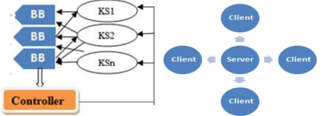
In the blackboard style the main components are shown in figure 1.Here blackboard is a shared repository. It is used by several knowledge sources to solve the problem. Each knowledge source tries to solve the problem and writes its solution, partial solution or suggestion on the blackboard. Simultaneously all other knowledge sources either modify or extend the solution given by previous knowledge source, or writes in its own way to solve the problem9.Thus knowledge source works together to solve the problem. Control shell is used to coordinate and manage the activities of the knowledge sources so that they cannot create any mess-up which can deviate the project from its actual direction. That is all the activities which are performed during problem solving session are manage, control and co-ordinate by control shell.
One of the advantages of this architecture is Scalability i.e. Knowledge source can be easily added or removed from the system as per the requirement. Knowledge sources are independent to each other and hence can work concurrently under the restriction of controlling element.
Difficulty in determining when to stop the solution finding process since more and more refinement to a solution is always possible is a problem in this architecture i.e. termination condition is not priory known. Synchronization of multiple knowledge sources is difficult to achieve10
BB=Blackboard ; KS=Knowledge Source
Fig. 1. Blackboard architecture Fig. 2. Client Server Architecture
2.2 Client–server architecture
Today most of the application which we use to access the Internet or application that we use on Internet is based on client server architecture. Here we divide the entire system into two parts, one act as a client and other as a server11. Most of the web applications are based on client server architecture. There are mainly three components shown in figure 2:
x Client: Client process is requester of the service or information. Example: Browser, Online chat client, Email client etc.
x Server: Server process accepts the request of the client, performs the processing, gathers the required information, generates the solution for the client’s demand and sends the generated solution to the client
process. After sending the service server is ready to accept other demand. Example: Print server, Web server, Database server, chat server, FTP server etc.
x Medium of communication of client and server: It defines the path by which client and server communicate with each other. E.g.-Internet, Intranet, Bluetooth network etc. In figure 2 arrows represents medium of communication which is bidirectional.
For example, in a network several computers are connected among which one computer will act as print server (on which printer server is installed) and others are client. Client computer will request print server computer to print a document .If the print server is free it will serve the request and print the document but if print server is busy it will place the request of the client in the waiting queue. Some important points about this architecture:
x Whoever generates the request will act as client.
x Whoever serves the request will act as server.
x Client needs to know the address of the server to send the request but server doesn’t need to know about the
location of the client.
x One server can approach other server to serve the client.
x According to requirement, client can become server and server can become client. Sometime a system can act as both server and client12.
Types of client server architecture:2-Tier Architecture: In this architecture client and server communicate with each other without any intermediate point or node. Although this architecture provides fast service but it suffers from security and performance holes. Example: Internet Explorer uses 2-tier client server architecture.3-tier architecture: Here one more node called middle tier sits in between client and server. Middle tier takes the request from the client, authenticate and approve it then pass it to the server13. Again middle tier takes the response from the server and pass it to associated client after proper verification and validation. Middle tier acts as load balancer in case of heavy load and also improves the security of the system.
Increased Security i.e. storing data on the server rather than client machine provides higher security. Client server architecture facilitates centralized data access facility through storing data on server. Enhanced data sharing is also here. Dependency on server i.e. if the server goes down entire system would stop working could be a problem here. Also Congestion in the network may slow down the operation.
2.3. Component-based Architectural Style
Component-based architectural style is based on the concept of separation of concern. According to the principle of separation of concern, a system is divided into several partitions such that each partition deals with separate concern. That is using this style divides the system into some logical or physical components with well-defined interfaces such that each component defines a specific functionality or information. Here a component could be a piece of information, data, functionality, resource, package, web service etc14.
Types of components:
x Fully or partially experienced components: Components available in the library of the organization which has been used in developing various systems.
x Off the shelf components: Components available in the library of third party.
x New component: These components are nowhere available neither in third party library nor in owns library thus needs to develop from the scratch.
Since system is divided into several components so one can easily use components of one system into other system.
Thus it provides the facility of reusability15.It follows the approach of HIGH COHESION LOW COUPLING
between the components of the system. High cohesion means a component perform a single related task and low coupling means components should have less dependency among them. A component can be easily extendable to add more functionality or data in it. Since system is made up of independent components so it will be easy to find out erroneous component16. In order to maintain the system to improve functionality or to correct error one can easily replace old module with new. One can easily find out the required component from third party libraries thus results in easy and speedy development of the system17.Reusability concept would not be there if it’s a case of adaptation of new technologies thus main benefit of this architecture is of no use in such a case. Some disputes like
“system evolution”, “compatibility”, migration will always be there18
.
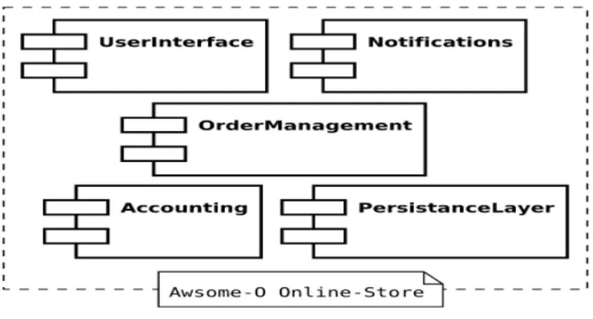
Fig. 3. Component Based Architecture
In the figure 3 there are 5 components in the system: 1. User Interface: For interaction of the user to the system 2. Notification: It notifies about the interaction of the client to the system and also notify client according about the response from system 3. Order Management: It manages the order from the clients. 4. Accounting: It manages all payment related task 5. Persistence layer: Storage of information or data Component Models: It specifies how to implement, document and deploy a component. Some standard component models are Enterprise JavaBeans (EJB)
model and Common Object Request Broker Architecture (CORBA) component Model 18. We can further divide the components into subcomponents to display the system with low level of abstraction.
2.4 Event driven architecture
Event driven architecture represents the system in terms of generation, processing, monitoring and termination of
events which can occur in a system. Here the term event refers to “change in state”. Sensing devices like controllers,
sensors etc. are used to detect change in state of an object19. Example when we switch on the button the state of
electric bulb changes from “OFF” to “ON”. Event driven architecture comprises four logical layers or architecture
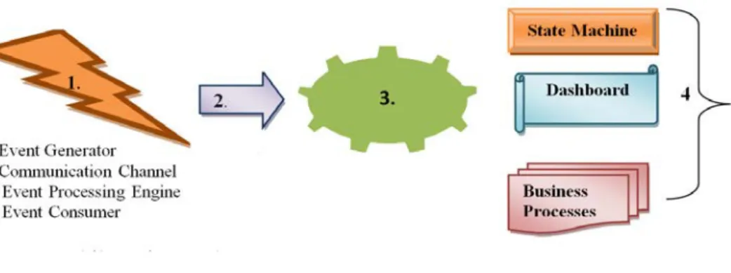
elements: 1. Event generator: This layer is responsible for the generation of the event i.e. event source reside in this layer. Event source could be clicking mouse, pressing key of a keyboard, Email client etc. 2.Event Channel: It is needed to transfer the event from its source to the event consumer i.e. event engine or sink. After generation events are stored in a queue later they are transported to the sink with the help of event channel. Event channel can be a TCP/IP connection or any input file like in XML form etc.20. 3. Event processing engine: This is the place where events are processed and appropriate responses are generated with respect to the event. 4. Downstream event-driven activity: Here consequences of events are shown. E.g. Sending mail without subject displays the warning Message. Thus sending email is an event and error message displays the consequence of the event. It best suited to
develop interactive system (e.g. GUI).Thus it is very useful for most of the today’s applications. It can be slow
because some time it takes long to process an event. It results in a complex system21.
Fig 4: Event Based Architecture
2.5.Pipes and filter software architecture
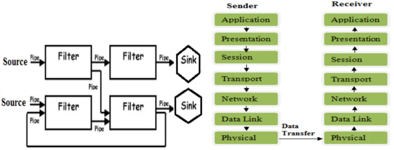
Here Filter refers to processing element and pipes are used to connect filters in such a way that output of one filter acts as input to the next filter. In between two filters there may be some intermediate elements which can act as buffer to manage the flow of information. It is unidirectional software architecture shown in figure 5. Thread, processes are examples of filters. This type of architecture is used in UNIX operating system. All the filters can run at the same time and can be distributed over different systems22. The first filter connects to the source and the last filter links to the sink. Pipe connection should be done properly so that output of one filter enters into correct filter. Independent filters can work simultaneously but filter which are getting input from the previous filter needs to wait to get the input. This architecture is used to speed up the processing, since multiple processing is going on same time in several filters.
Pump or source is used to give input into the system, this input passes through the pipe to the connected filter .Filter performs the processing on the data and forward the output to the next filter for further processing, at the same time pervious filter will take other input and will perform processing thus it reduces the stalls in the entire processing. The performance of the system is improved by removing the stalls present in the processing. Thus increased throughput is given by such system. Filters are loosely coupled to each other since they do not exchange their state.
Increased maintainability i.e. this system includes more components results in requirement of greater management and maintenance of components. Since states are not shared in this style thus error handling and solving is tuff here23.
Fig. 5: Pipe and Filter Architecture Fig. 6. Layered Architecture
2.6Layered Architectural Style
Layered architecture groups the responsibilities of the software into several loosely coupled layers. A system is layered on the basis of separation of concern. Layers can communicate with each other through well-defined interfaces. Since layers are loosely coupled they can reside on a single computer or may be distributed over several computers. Commonly a software system is divided into three layers: Presentation Layer: This layer incorporates user interface functionalities. Through this layer user can interact with the system. Business Layer: This layer incorporates the business logic of the system. Infrastructure Layer: This layer incorporates data services, networking services and other infrastructure services in it. External clients or application can directly use the services of business layer through service interface. Example: The best example of layered architecture is presented in OSI (Open system interconnect) and TCP/IP model. In OSI model services of the system is decomposed into seven distinct layers shown in figure 6. OSI model represents in a network how one system communicates with other irrespective of their internal differences. Physical layer represents the topology (star, bus, mesh, hub etc.), configuration (point to point, multi-point) of the network24. Here data is represented in the form of bits. Data Link Layer is responsible for the node to node delivery of the data locally. It performs local error and flow control. Data in this layer is represented in the form of frames. Network Layer is responsible for host to host delivery of data. It performs routing of packets from one node to next. Data in this layer is represented in the form of packets. Transport Layer is responsible for process to process delivery of the data. It performs global error and flow control. Data in this layer is represented in the form of datagram or segment. Session Layer is responsible for the session management for a user. It performs dialogue controlling and synchronization with the help of checkpoints. Presentation Layer is responsible for encryption, translation and compression of the data. Application layer incorporates user services i.e. it acts as user interface layer24. Thus application layer and data link layer acts as presentation and infrastructure layer respectively whereas other layers in between these two altogether acts as business layer. One can work on the different layers of the system at a time and easily scale and maintain the system. Here users are not calling a component directly instead making communication through layers. It can slow the entire communication between different components of the system. Also exact number of layers for a system is difficult to find out.
3. Some new and complex system architecture
3.1 Cloud Computing Architecture
Cloud computing architecture consists of different components required for cloud computing, relationship between these components and the properties of relation and components. Major components of cloud computing is shown in figure 8.
Front end platform: It includes cloud clients which can be any software or hardware which is dependent on the
cloud computing to get services. Cloud client can be browser, operating system, mobile phone, tablet and other devices. Examples: Android (operating system), Smartphone, Yun OS, OPhone, Google Chrome, Cloud Book, MIUI etc.
Backend platform: It includes server and storage .Backend platform or cloud storage means storing data on
Internet or in cloud which can be accessed by cloud clients. It can be developed in several forms like public, private, community and hybrid cloud25.
Fig. 7. Cloud based delivery Fig. 8. Cloud computing architectural components
Cloud based delivery: Cloud based delivery means cloud service model which include following services shown in
figure 7.Software as a service (SaaS):SaaS is also known as ON DEMAND SOFTWARE. Here cloud providers install and maintain various software in their cloud which are available for cloud clients to execute their tasks. Cloud client use these software with the help of Network. Example: Microsoft BPOS, Microsoft Dynamic CRM Online, Google docs- online word processor etc. Hence with the help of SaaS client can use different software online thus could be able to get rid of following responsibilities:
x Time to time updation of software
x License updation
x Installation of software
x Maintenance of software
SaaS can implement in any one of the following architectural ways: 1. Single Instance 2. Multi instance 3. Multi Tenancy 4. Flex Tenancy. Here the most common and widely used way is Multi Tenancy. Multi tenancy is one of the styles among several software architectural styles and patterns which consists of single instance of an application with multiple tenants .Tenant refers to cloud clients i.e. departments, organizations or different forms of users26.
“Multi Tenancy refers to the capability to host a single instance of a software solution that serves multiple clients.”
Multiple tenant uses the single software instance provided using SaaS. Multiple view of the same software is provided through single codebase, database and other software and hardware resources. The software is architect by virtually dividing its data and configuration and each tenant access a customized virtual application/software. For example suppose three tenants are sharing the same application by individual customized view. Each tenant has its
Cloud Based Delivery SaaS IaaS PaaS Front End Platform Cloud Based Delivery
Network Back End Platform
Cloud Computing Components
unique id. Meditation layer determines tenant id in each request. With the help of unique id respective requests are served to the respective tenant. Hence each tenant is having its own customized virtual view and use of software which is completely isolated and secure from other tenants. Pros and cons of multi tenancy: Pros: Cost benefits: Since single software is getting shared by multiple clients hence we need to provide cost for maintenance, updation, database management etc. for one software only. Example: License updation for only one software. Operational benefits: Since all the application code for different tenants is in one place it is much easier to change, update, backup and maintain the code just by changing the single software. Hence with change at one place several tenants can enjoy the updation. Database related benefits: Here all the data for different tenants is stored in a single database schema hence management of data is easier. Also there will be a homogeneous collection of data which will be heterogeneous if users have different software for different clients. Thus mining data, executing database queries will be easier with multi tenancy architecture. Cons: Challenging customization: Since each client is having its own customized view of the software, it would be challenging to prepare and maintain separate customized view for each client. Customization should be done in all the dimensions according to the requirements of the tenant like brand, workflow, and extension to data models and standards27. Loss of customer in case of damage to the software: If software is not working correctly, infected by virus, crashed or damaged, all customers linked to the software are going to be affected by the single problems. Hence in such a case all the customers can leave the cloud containing the software thus resulting in loss of more customer than if we are having separate software for each customer. Security: It requires high security provisions since with multiple clients on the same software can result in breech the data if they are not properly managed and isolated. In case of security breach data or work of one client will be available to all clients. Isolation: It would be challenging to isolate clients so that one client cannot interfere or being interfered by other client. Downtime: If software requires to get updated, this updation time would serve as a downtime to all connected clients. Thus more clients are going to be affected at the same time. Multitenant architecture is not only limited to application, it can be applied to Data centre floor, operating system, Infrastructure and platform. Basically we have five types of multitenant architecture given below:
x Physical Level
x Hypervisor Level
x Operating System Level
x Platform Level
x Application Level
Platform as a service (PaaS): With PaaS as a service model cloud providers provide development, computing and testing environment to the cloud clients. Thus with the help of PaaS customer can develop software using services, framework, platform, tools, programming language and libraries provided by cloud providers. It also facilitates customer by giving complete testing, deployment and configuration facilities for the developed software. Thus results in reducing effort in building, maintaining and updating development environment for the client. Examples: Google App Engine, Apprenda, Cloud Foundry, IBM Bluemix, OpenShift, Wavemaker, Microsoft Windows Azure. Infrastructure as a service (IaaS): With IaaS cloud providers provides IT infrastructure services on demand like physical or virtual machines, servers, storage, firewall, load balancer and other infrastructure based services to the cloud client27. Example: Google drive, Linode, Zadara storage etc.
Network: Cloud network means the medium with which cloud clients can access the cloud and cloud providers can provide the services to the cloud clients. It could be Internet, Intranet or Inter-cloud. Network for cloud computing should contain following benefits: High bandwidth: It delivers smooth and fast cloud services to the clients. Security: Network should be secure because of existence of multi-tenant architecture. Agility: Network can easily incorporate the enhanced load and hence can easily deliver resources and services to the client. In spite of having many benefits like free from hardware maintenance, increased scalability etc. cloud computing is not free from flaws. There are various challenges like data security issues, increased bandwidth cost and interoperability issues.
3.2 Architecture for Big Data
Big data as its name indicates is a huge and complex dataset thus difficult to process and manage with existing traditional data processing application28.Big data can be defined by three dimensions- Volume, Velocity and Variety. Volume: It refers to huge amount of data which is difficult to capture process and manage by commonly used software tools. 2.5 Exabyte of data is creating every day. One of the sources of such big data is Social networking profile like Facebook, Tweeter, Google, LinkedIn etc. Velocity: It refers to the speed with which data enter into an organization and getting out from the organization. Thus organization must be able to work with the speed of data. Variety: It refers to different forms i.e. heterogeneity of data. Data can be in different forms like audio, video, text, structured, semi structured, unstructured, numeric, binary etc. To process such data requires much effort and complex techniques. Hadoop framework is suitable for big data storage and processing that cover velocity, volume and variety requirements. It is an open source framework given by Apache, consists of two main components: HDFS (Hadoop Distributed File System) and Map Reduce shown in figure 9.HDFS: It is a file system which breaks the huge data into chunks and replicates the chunks three times for the reliability purpose. HDFS default size for chunks is 64 MB and replication is done three times. However size of chunk and replication factor can be change as per the requirement. Map reduce framework consists of parallel processing model to process huge amount of data. It is a programming model for data processing. It consists of two procedures: Map(): Here input is submitted to the master node which divides the input into smaller chunks and distribute these chunk problems to the several connected worker node. Each worker node can further divide the chunks till it become possible to solve, thus forms a hierarchy. Chunked problems are solved by their connected worker node. After solving, worker node return the solution to the immediate master node, internal master nodes passes the solution to the top of the hierarchy via intermediate master nodes29.
Input<key,value> pairs in the Map() function. Map function gather all the pairs with identical key and form a group of all the values belonging to same key thus one group per key. Map(k1, v1) → list(k2,v2) Reduce(): Master node combine the solutions obtained from worker node and generate the combined output in the required format. Reduce() function is applied in parallel to each group. Thus each Reduce() function merges and apply required
operation on the group to produce zero or one output value. Reduce(k2, list (v2)) → list(v3).Hadoop is scalable and reliable big data processing architecture31. It provides both big data storage and big data processing facilities. But, Hadoop suffers from the problem of single point of failure, which is master node.
Fig. 9.Architecture of Big Data30
Fig. 10. Architecture of Grid computing
•Discipline specific Data Grid Application Application •Coherency Control,task management Collective(App lication)
•Replica catalog and management,Co-allocation Collective(Gen eric) •Access to data,Access to computers Resource •Communication,Authentication .Authorization Connect •Storage Systems,Clusters,Networks, Fabric
3.3 Architecture of Grid computing
Grid computing is an extension of distributed computing in which resources of several computers in a network are used together to accomplish a common job. Example: take real life examples suppose three friends A, B, C planning for a picnic. A is having cab for transportation, B is having food and C is having tent. So if they move individually no one can be able to complete the trip. But if they move together they can share the tent, food and cab and will have a wonderful picnic. This is an example of grid computing32. In a network of computers, each computer is having its own processing power, storage and peripherals. But to complete a complex task individual computer would not be sufficient because of limitations on its resources. Although we can scale a computer but still there will be some limitation to the enhancement of a computer. Here the solution is grid computing. To complete a complex task resources of computers connected in the network are utilized together. We can think this network of cooperating computers as a single supercomputer. The computers in the network can be loosely coupled, heterogeneous and geographically distant.
Architecture of grid computing follows the layered style which is depicted in figure 10. Layer by layer description: Fabric Layer: It provides resources and interfaces which are required to access the resources in the Grid network. Grid involves both physical and logical resource33. Physical resource: Server, sensor, storage, catalog, computational resource etc. Logical resource: Distributed file system, computer cluster etc. Connectivity Layer: This layer deals with how different computers or nodes in the grid will communicate with each other. It defines communication and authentication protocols for smooth and secure resource sharing. Authentication protocols above communication protocol define various security provisions like cryptography, authorization and controlled access to resources. Resource Layer: It works for individual resource. For each individual resource it control and manage its beginning, monitoring, control, negotiation, payment and operation. Three main protocols which works here are: GRAM (Grid Resource and Access Management), Grid FTP, GRIS (Grid Resource Information Services). Collective Layer: It works for the entire grid. It manages the coordination among the resources in the grid. It provides different types of services like data replication management, Meta data services, directory services like MDS (Monitoring and Directory Services), scheduling services, broking services like MPICH and CAS (Community Authorization Services).Application layer: It defines user specific services i.e., user applications through which user interact with the Grid34.Apart from the advantages such as increased throughput, higher scalability and fault tolerant architecture, it needs more management to work with distributed resources.
4.Conclusion
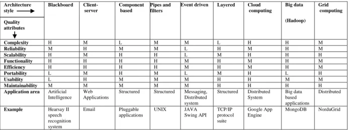
This survey provides a complete picture of all the important architectural styles with three modern and complex system architectures (Cloud Computing, Big Data, and Grid Computing).All above discussed architectural styles are compared on the basis of quality attributes i.e. Complexity, Reliability, Scalability, Functionality, Efficiency, Portability, Usability, Maintainability and presented in the table 2. They are also compared on the basis of application areas. Since Blackboard architecture is mainly used in the field of Artificial Intelligence, it results in high complexity because artificial intelligence applications are difficult and devious to build. It is a suitable architectural style for artificial intelligence applications like Hearsay II, Copycat, OCR Text Recognition, GTXImage etc. Thus the application area of blackboard architectural style can be Robotic systems, Speech recognition system, Text recognition system, Earth observation satellites etc. It provides high functionality and efficiency in the application. Use of Internet is increasing day by day results in heavily used of client server architectural styles in the web based applications. Some examples of web based software are: AceProject, Ganttic, Celoxis etc. For a server based application supporting many clients which is going to be used by a web browser uses client server architecture model. It is also applicable in application area for centralized resource system (like management functions, storage) which is going to be used by many clients. Heavily used and famous example for client server architecture application area is email, World Wide Web, FTP software, e-commerce applications. The complexity of such applications is not as high as blackboard based applications. Client server based applications keeps high functionality and efficiency. 3-tier client server applications have good reliability because of middle tier which perform all security related task. Component based architecture should be used when there are several similar projects hence module or components developed for one project can be easily utilized in other. Component based architecture should be adopted when suitable components are available to develop a project by reusing them.
Reusability is the main feature of component based architecture. When schedule to develop the project is very small so to get the project in minimum possible time existing components can be reused. To create pluggable applications this architecture will be appropriate. Since whole picture of system is in terms of components, it results in high maintainability and portability. Also we can easily attach a new component thus on demand, it will be easy to scale up such system. Pipe and filter architectural style is mainly used in multitasking operating systems. It is also good for compiler development. There are many applications required to process huge volume of similar data items e.g., application for billing system of telecommunication sector where ample of call records are processed to calculate the total payment. Application involving lots of transformation of data items and where it is easy to decompose the processing into independent discrete pieces for each filter, Pipe and Filter architectural style will be a good option to develop such system. Instructions inside the computer are processed using instruction pipelining which is based on pipe and filter architectural style. It provides high efficiency and high functionality because it reduces stalls in the system. It provides average maintainability to the developed system. In case of Event driven architectural style, it is suitable for highly distributed applications and application involving transmission of events among software components. Example is JAVA Swing API which is based on event driven architecture. It shows average performance in most of the quality attributes. Layered architectural style should be used in application which can be divided into several layers on the basis of services or functionalities in such a way that lower layer forms the basis for upper layer. Division of system into layers leads to easy debugging and flexible to update and maintain in future. Cloud computing architecture is for cloud based applications like Gmail drive, Google App Engine. It has limited functionality since till now it has not covered all the requirements of information technology. Higher scalability is the main feature of this architecture. Big Data is very new concept developed because of availability of huge amount of data. Architecture of Big Data is used in Big Data based applications like MongoDB, Datameer ,Hadoop ,Spark ,Splunk etc. Complexity of Big Data based applications is very high. Because of high complexity it results in medium maintainability. Traditional software is not able to handle Big Data. Grid computing architectural style is used in Grid based applications like gLite, ProActive, Sun Grid Engine, UNICORE etc. Since Grid involves several computers hence it is easy to scale up such system. It keeps medium complexity and average functionality. Although all architectural styles presented in this paper have their own importance but in the recent era of very large databases cloud computing, Big data processing and grid computing based architectures are emerging as a key tool for business intelligence and efficient processing. This paper could be further extended with more exhaustive and inclusive coverage of all these techniques along with their recent developments.
Table 2. Comparison of architectural styles and patterns
In Table 2, H stands for HIGH. M stands for Medium . L stands for LOW. Architecture style Quality attributes Blackboard Client-server Component based Pipes and filters
Event driven Layered Cloud computing Big data (Hadoop) Grid computing Complexity H M L M M L H H M Reliability M H M M L H M H M Scalability H M H H L M H H H Functionality H H H H M H M H M Efficiency H H H H M H M H M Portability L M H M L M H L H Usability L H M M M H H M M Maintainability M M M M M H H H H
Application area Artificial Intelligence
Web Applications
Structured Structured Messaging,
Distributed system Structured Distributed System Big data based applications Distributed Example Hearsay II speech recognition system Email Pluggable applications UNIX JAVA Swing API TCP/IP protocol suite Google App Engine MongoDB NorduGrid
References
1.Bosch, Jan. "Software architecture: The next step." Software architecture.Springer Berlin Heidelberg, 2004.194-199. 2. Fairbanks, George. Just enough software architecture: a risk-driven approach. Marshall & Brainerd, 2010
3. Lindström, Åsa, et al. "A survey on CIO concerns-do enterprise architecture frameworks support them?" Information Systems Frontiers 8.2 (2006): 81-90
4. Bass, Len, Paul Clements, and Rick Kazman. Software architecture in practice. Addison-Wesley Professional, 2003. 5. Shaw, Mary, and Paul Clements. "The golden age of software architecture." Software, IEEE 23.2 (2006): 31-39.
6. Buschmann, Frank, Kelvin Henney, and Douglas Schimdt. Pattern-oriented Software Architecture: On Patterns and Pattern Language. Vol. 5. John wiley& sons, 2007
7. Garlan, David. "Software architecture: a roadmap." Proceedings of the Conference on the Future of Software Engineering.ACM, 2000. 8.Dobrica, Liliana, and EilaNiemela. "A survey on software architecture analysis methods." Software Engineering, IEEE Transactions on 28.7
(2002): 638-653.
9. Hayes-Roth, Barbara, et al. "A domain-specific software architecture for adaptive intelligent systems." Software Engineering, IEEE Transactions on 21.4 (1995): 288-301.
10. Dong, Jing, Shanguo Chen, and Jun-Jang Jeng. "Event-based blackboard architecture for multi-agent systems." Information Technology: Coding and Computing, 2005. ITCC 2005.International Conference on.Vol. 2.IEEE, 2005.
11. Kekic, Miodrag M., Grace N. Lu, and Eloise H. Carlton. "Client-server computer network management architecture." U.S. Patent No. 6,664,978. 16 Dec. 2003.
12. http://www.cs.montana.edu/~halla/csci466/lectures/lec2.html
13. Davis, Keir, John W. Turner, and Nathan Yocom. "Client-Server Architecture."The Definitive Guide to Linux Network Programming.Apress, 2004. 99-135. [14] http://java.boot.by/scea5-guide/ch02s02.html
14.Heineman, George T., and William T. Council. "Component-based software engineering: putting the pieces together." (2001).
15.Mahmood, Sajjad, Richard Lai, and Yong Soo Kim. "Survey of component-based software development." Software, IET 1.2 (2007): 57-66. 16.Garlan, David, Robert T. Monroe, and David Wile. "Acme: Architectural description of component-based systems." Foundations of
component-based systems 68 (2000): 47-68.
17.Herzum, Peter, and Oliver Sims. Business Components Factory: A Comprehensive Overview of Component-Based Development for the Enterprise. John Wiley & Sons, Inc., 2000.
18.http://docs.apiwatch.org/en/apiwatch-0.1/user/basic-concepts/
19.Bruns, Ralf, ed. Event-Driven Architecture. Springer Berlin Heidelberg, 2010.
20.Chandy, K. Mani. "Event Driven Architecture."Encyclopedia of Database Systems.Springer US, 2009.1040-1044. 21. http://www.ibm.com/developerworks/library/ws-eventprocessing/
22.Mehta, Nikunj R., and NenadMedvidovic. "Composing architectural styles from architectural primitives."ACM SIGSOFT Software Engineering Notes.Vol. 28.No. 5.ACM, 2003.
23.Rapanotti, Lucia, et al. "Architecture-driven problem decomposition." Requirements Engineering Conference, 2004.Proceedings.12th IEEE International.IEEE, 2004.
24. msdn.microsoft.com/en-us/library/ee658109.aspx
25. Dinh, Hoang T., et al. "A survey of mobile cloud computing: architecture, applications, and approaches." Wireless communications and mobile computing (2011).
26. Zhang, Qi, Lu Cheng, and RaoufBoutaba. "Cloud computing: state-ofthe-art and research challenges." Journal of internet services and applications 1.1 (2010): 7-18.
27. http://natishalom.typepad.com/nati_shaloms_blog/2010/03/multitenanc y-does-it-have-to-be-that-hard.html [29] Rimal, Bhaskar Prasad, Eunmi Choi, and Ian Lumb."A taxonomy and survey of cloud computing systems."INC, IMS and IDC, 2009.NCM'09.Fifth International Joint Conference on.Ieee, 2009.
28. Manyika, James, et al. "Big data: The next frontier for innovation, competition, and productivity." (2011).
29. http://blog.sqlauthority.com/2013/10/02/big-data-what-is-big-data-3-vs-of-big-data-volume-velocity-and-variety-day-2-of-21/ 30. http://www.glennklockwood.com/di/hadoop-overview.php
31. Chen, Yanpei, Sara Alspaugh, and Randy Katz. "Interactive analytical processing in big data systems: A cross-industry study of MapReduce workloads." Proceedings of the VLDB Endowment 5.12 (2012): 1802-1813.
32. Foster, Ian, and Carl Kesselman, eds. The Grid 2: Blueprint for a new computing infrastructure. Elsevier, 2003.
33. Berman, Fran, Geoffrey Fox, and Anthony JG Hey, eds. Grid computing: making the global infrastructure a reality. Vol. 2.John Wiley and sons, 2003.
34. Parashar, Manish, and Craig A. Lee. "Grid Computing: introduction and overview." Proceedings of the IEEE, special issue on grid computing 93.3 (2005): 479-484.