Developing Complex Systems using
DOORS and UML
Telelogic 2004 User Group Conference –
Americas and Asia/Pacific
Michael Sutherland
Abstract
In order to successfully develop complex systems, developers are frequently relying on visual languages (Use Case Diagrams, State Diagrams, etc.) for the modeling of system functional behavior, in addition to using traditional textual requirement (shall statements, etc.) based development.
This presentation will demonstrate a system development methodology, which integrates the industry leading Requirement Management tool (Telelogic DOORS), and the industry standard language for Functional Modeling (The Object Management Group's (OMG) Unified Modeling Language (UML) ). Topics will include:
(1) Organization and structure of a UML Model as represented in a DOORS Surrogate Module
(2) Generating UML Use Cases from System Requirements
(3) Using UML and Operational Contracts to generate Functional Requirements (4) Traceability between Textual Requirements and UML Model Elements
Introduction
UML
The OMG (Object Management Group) specification states:
"The Unified Modeling Language (UML) is a graphical language for visualizing, specifying, constructing, and documenting the artifacts of a software-intensive system. The UML offers a standard way to write a system's blueprints, including conceptual things such as business processes and system functions as well as concrete things such as programming language statements, database schemas, and reusable software components."
DOORS
The Telelogic web site states:
“Telelogic DOORS®, the world's leading requirements management tool, is a multi-platform, enterprise-wide system designed to capture, link, trace, analyze and manage changes to information to ensure a project's compliance to specified requirements and standards.”
Background
General Dynamics Land Systems (GDLS) and United Defense Limited Partnership (UDLP) were selected by The Boeing Company and Science
Applications International Corporation (SAIC), the Future Combat Systems (FCS) Lead System Integrator (LSI), to form an integrated design team for the Manned Ground Vehicle (MGV) portion of the FCS program.
The FCS LSI chose a “one model” approach to development, where the entire FCS “System of Systems” (SOS) will be modeled in UML, and all suppliers will provide UML models which will integrate with the SOS. The FCS LSI selected Telelogic DOORS as the tool for requirements management, and selected IBM Rational Rose as the tool for UML modeling.
UML does not prescribe a specific process for modeling, and DOORS does not prescribe a specific process for requirements management. Given the need for specific processes, GDLS and UDLP have developed a process for MGV Systems Requirements Analysis which includes processes to document requirements in DOORS, and model system behavior using UML. Among the process requirements is the need to establish traceability from customer provided
UML-DOORS Systems Requirements Analysis Process
The steps in the process steps are numbered 1-18. Terminology is explained in bulleted form.
System Requirements
1. Develop and evaluate System Level Requirements in DOORS.
Use Case Diagrams
Use Case Diagrams describe the functionality of the system from perspective of those that are outside it and interacting with it.
• Actor – An entity external to the system that plays a role by interacting with the system.
• Use Case – Functional behavior that the system will perform to provide value to the Actor.
2. Determine Actors and develop Use Cases from System Requirements. 3. Document the relationships between Uses Cases and Actors on Use Case
Diagrams.
4. Develop Traceability from Use Cases to the System Requirements they were derived from.
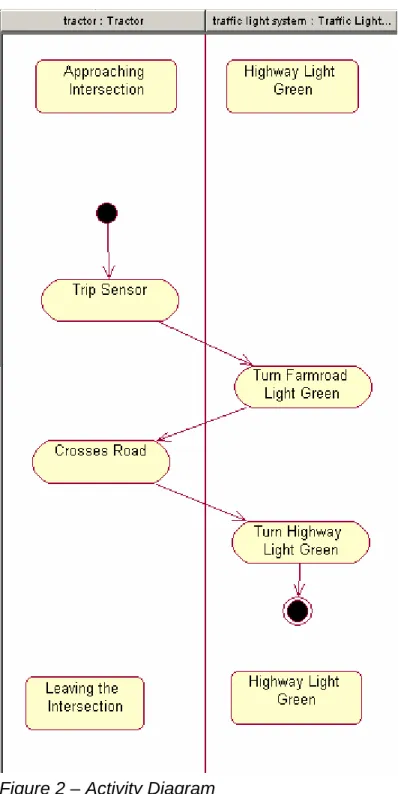
Activity Diagrams
Activity Diagrams are used to decompose Use Cases by describing the flow of events that comprise Use Cases.
• Swimlanes – Partitions that show which Objects are responsible for performing each Activity.
• Activity – A tangible unit of work.
• Transition – Flow of control between Activities. A transition occurs when an Activity is completed.
• State - A state is a named condition or situation in the life of an object, that lasts for some finite amount of time, during which the object satisfies some condition, performs some activities and/or actions, or waits for some event.
• Precondition – Initial State of Object
• Postcondition – Final State of Object
5. Determine the Activities that need to be performed to accomplish each Use Case.
6. Determine the Objects that will perform each Activity.
7. Assign each Object to a SwimLane on an Activity Diagram. A SwimLane shall represent exactly one Object.
8. Assign each Activity to a SwimLane on an Activity Diagram. A SwimLane may contain multiple Activities.
9. Document and the flow of control between the Objects as Transitions between Activities on Activity Diagrams.
10. Document the preconditions and postconditions for each Object in each Swimlanes on Activity Diagrams.
Note: Activity Diagrams are considered “Black Box” when they involve an Actor external to the System, and “White Box” when they only involve internal Objects. Note: Activity Diagrams are similar to traditional flow charts, and UML specifies a richer syntax to specify event flow. For example, forks, joins, guard conditions, and flow merges are possible.
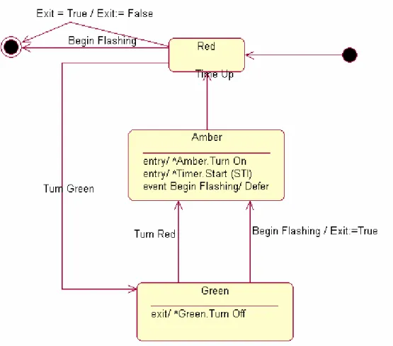
Statechart Diagrams
A Statechart Diagram is used to show events that cause a class to transition from one state to another state, and the actions that result from a class changing state.
11. Develop Statechart Diagrams (Sequence of states, stimuli, and response).
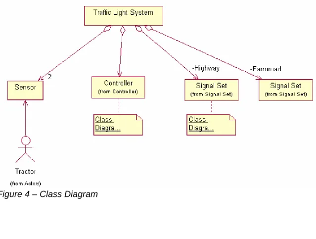
Class Diagrams
A Class Diagram documents relationships (Association, Aggregation, Composition, Dependency, Inheritance, Realization) between Classes. There is no single step called “Develop Class”, because Classes may be developed at any step. The following are all Classes that were developed in previous steps:
• An Actor on a Use Case Diagram
• An Object on an Activity Diagram (associated with a Swimlane)
• An Object on a Sequence Diagram (associated with a Lifeline)
Each Class has Attributes (or Properties), that define the data structure of the Class
Each Class has Operations (or Methods), that define the functions of the Class 12. Document relationships between Classes on Class Diagrams.
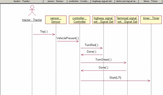
Sequence Diagrams
Sequence Diagrams describe the behavior of Objects, including the sequence of Messages between Objects.
• Message – Communication (interaction) between Objects. Messages should be bound to Operations.
• Operation – Function of a Class
13. Add Objects to Sequence Diagrams (breakdown activities). 14. Add Messages between Objects in Sequence Diagrams.
15. Document the sequence over time of the messages between Objects on Sequence Diagrams.
16. Bind each Message to an Operation, document on Sequence Diagrams.
Figure 5 – Sequence Diagram
Note: Collaboration Diagrams are Sequence Diagrams with messages labeled in hierarchical order to signify the sending order. Collaboration Diagrams
emphasize the relationships between the objects as opposed to the sequence of the messages.
Operational Contracts
An Operational Contract is defined for each Operation, to give precise detail about the preconditions that are necessary for the Operation to be executed, and the postconditions that result after the Operation is executed. Postconditions may include the creation and deletion of Class instances, modification of Class Attributes, and the formation or breaking of associations between Classes. An Operation may use parameters (data), and may return data.
17. Develop Operational Contracts
Generating Requirements from UML in DOORS
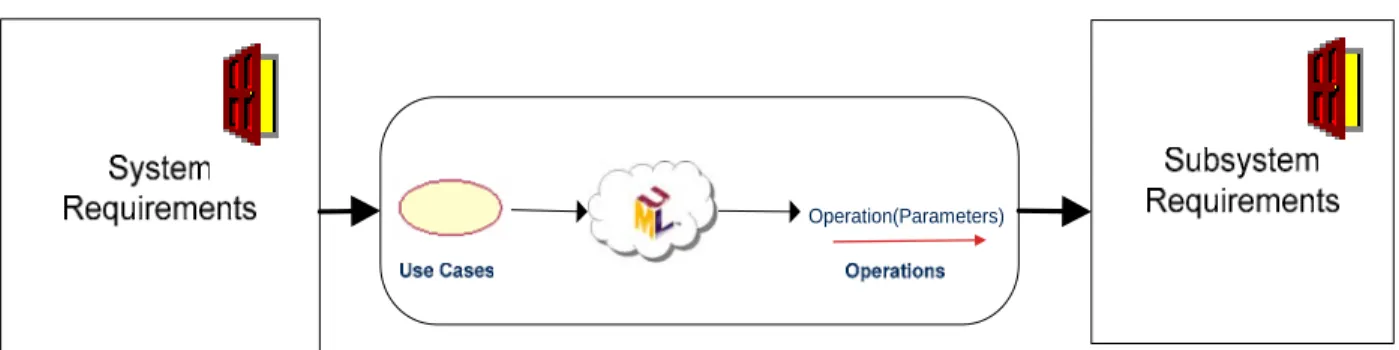
New Subsystem Requirements are derived from Operational Contracts,
documented in DOORS, and traced back to the Operation in the UML surrogate Module. An Operation may generate multiple Subsystem requirements, and a single Subsystem requirement may be generated from multiple Operational Contracts.
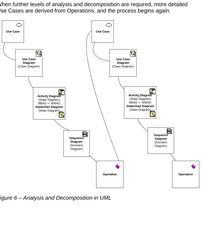
When further levels of analysis and decomposition are required, more detailed Use Cases are derived from Operations, and the process begins again.
Sequence Diagram (Scenario Diagram) Activity Diagram (State Diagram) BBAD <- WBAD Statechart Diagram (State Diagram) Use Case Use Case Diagram (Class Diagram) Sequence Diagram (Scenario Diagram) Activity Diagram (State Diagram) BBAD <- WBAD Statechart Diagram (State Diagram) Operation Use Case Diagram (Class Diagram) Use Case Operation
Traceability Between UML and DOORS
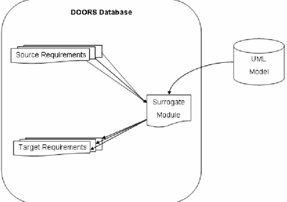
Figure 7 – Traceability between UML and DOORS
To accomplish requirements traceability between the two tool sets, a “surrogate” representation of the UML model needed to be available in the DOORS tool. Telelogic has developed a product called “Rose Link” to accomplish this task. GDLS evaluated this product, and found that even though it is a very capable integration, it did not fit well into the FCS MGV System Requirements Analysis process for the following reasons:
(1) No graphical representations of UML diagrams were made available in DOORS.
(2) Some UML elements and diagram types were not represented in DOORS in any form.
(3) Knowledge of the complex UML Browser hierarchy structure was not represented in the DOORS Module Explorer view.
(4) Knowledge of the relationships between UML elements was not well represented.
Because of the critical importance of establishing traceability throughout the System Requirements Analysis process, GDLS has developed a custom
integration between DOORS and Rose called “RM-Int” (Requirements/Modeling Integration).
RM-Int (Requirements/Modeling Integration)
The Requirements/Modeling Integration that was developed as part of the UML DOORS System Requirements Analysis Process has the following features:
Surrogate Module
Representing the UML Model in DOORS as a surrogate Module opens it up to a wider audience to consume. Daily synchronizations allow for timely
communication of changes. DOORS display control features such as filtering and sorting allow for custom views.
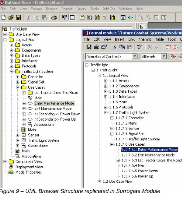
UML Hierarchy Browser
• A complex UML model in is organized into UML elements called Packages (folders). Packages are provided to group related elements. The
integration duplicates the UML browser hierarchy in the DOORS surrogate module.
Metrics
Metrics of the DOORS Surrogate Module are possible without additional
scripting. For example, the following table lists counts of UML element types for a given day: Activity 3272 Attribute 106 Category 2193 Class 967 Operation 937 State 2704 StateMachine 549 UseCase 539 UseCaseDiagram 224 ClassDiagram 658 PackageDiagram 316 SequenceDiagram 272 ActivityDiagram 563 StatechartDiagram 43
Traceability metrics are also possible. For example, a count of Operations that derive other Requirements could be taken, given the fact that in such cases the derived Requirements will be linked to the Operations.
Icons
Every UML element may have a stereotype and a corresponding Icon.
Displaying this Icon in a DOORS text attribute allows for a concise display and quick identification of UML elements. Requirement Engineers may not be familiar with these Icons, so the stereotype name is also available in a DOORS attribute.
Diagrams
Diagrams serve to communicate much of the UML content. Without adequate representation in the surrogate UML module, it would not be possible to
comprehend the model. The UML integration brings in a Visio bitmap
representation of each diagram. Visio was chosen because of the availability of pan and zoom functions.
Elements deleted from Model
As the UML Model changes, elements will be deleted. The DOORS application will not allow them to be deleted until the incoming links are removed. Such elements are marked as deleted in the surrogate module. This mechanism forces requirements engineers who have generated requirements from the model to be informed that model elements they were previously utilizing has been
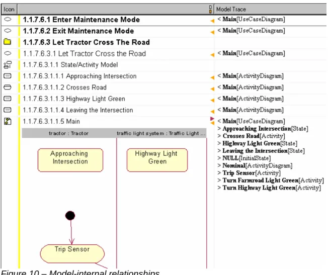
Model-internal Relationships
The Packaging standards used for complex models may dictate that related elements reside in different parts of the UML hierarchy, including residing in different packages. To increase navigability, DOORS links are created in the UML surrogate from UML diagrams to the UML elements that are on the diagrams.
• Use Case Diagram -> Use Case
• Use Case Diagram -> Actor
• Class Diagram -> Class
• Activity Diagram -> Activity
• State Diagram -> State
• Sequence Diagram -> Operation
UML also supports linking via an element called a Note, and specifically allows one UML diagram to link to any other diagram. For example, an Activity diagram will be note-linked to the Use Case diagram that it was generated from.
• Diagram-> Diagram
Non-diagram elements also have relationships that need to be navigated:
• Operation -> Class
• Operation( Parameter[1-n] ) -> Class[1-n]
• Class( InheritRelation[1-n] ) -> Class[1-n]
The following example shows a portion of a UML model represented in a DOORS surrogate module. The “Model Trace” Column on the far right shows detail about the model-internal relationships for each UML element.
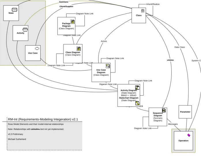
Complete model-internal relationships
The diagram below shows all model-internal relationships represented by RM-Int.
Data Class
Diagram Note Link Digaram Note Link
Messages
Parameter
Diagram Note Link
Diagram Note Link Diagram Note Link
Digaram Note Link Actors
Lifeline Diagram Note Link
Diagram Note Link
Sequence Diagram (Scenario Diagram) Activity Diagram (State Diagram) BBAD <- WBAD Statechart Diagram (State Diagram) Diagram Note Link
System Class Operation Swimlane Activity Swimlane Client/Supplier Use Case
Rose Model Elements and their model-internal relationships Note: Relationships with strikethru text not yet implemented. v0.3 Preliminary
Michael Sutherland
RM-Int (Requirements-Modeling Integeration) v2.1
State Use Case Diagram (Class Diagram) Package Diagram (Class Diagram) Class Diagram (Class Diagram) Inherit/Realize Class
Benefits
The main benefits this effort has achieved are:
• Requirements Engineers now access the updated UML model in a consistent manner, where before they received arbitrary exports from the UML modeling tool at the modeler’s discretion.
• Requirements Engineers have the ability to establish traceability from UML to source requirements and derived requirements in a manner consistent with other traceability procedures for the project.
• Modelers can now better comprehend the how a change to the UML model will impact the system.
Conclusion
Modeling a complex system with UML has proven to be a daunting task.
Traditional requirements engineers, while having a wealth of domain knowledge, have had difficulty expressing this knowledge in UML. Given this, the project decided to add experienced UML modelers to facilitate the task. Experienced UML modelers, while having a deep knowledge of expressing concepts in UML, often enter the project with no domain knowledge. Bridging the gap between those with domain knowledge, and those with UML knowledge, has been one of the main challenges faced when developing a System Requirements Analysis Process.
Appendix
Comparison of Rose Link v2.8 and RM-Int 2.x
DOORS Integration for Rational Rose (RoseLink) v2.8
The Rose Link manual states the following with regards to the organization of elements in a surrogate Module:
“The objects in the surrogate module are organized in a hierarchy based on the type of the model Element”
“When you send class elements, you can also send the operations and attributes associated with the class. Each operation and attribute becomes a child of the class object.”
RM-Int 2.x
The objects in the DOORS surrogate module are organized in a hierarchy based on the Rose browser structure. This allows for modelers to navigate the same organizational structure.
Requirements engineers may not understand this structure, so views are created to help them navigate.
The structure of elements in a Rose Browser is based on the parentage rules for UML elements, and also based on placement of elements in packages
(controllable units). Controllable units are used so that multiple modelers can be working on parts of the model at the same time.
Rose Elements
Rose Class Rose Stereotype Appears in Rose Browser RoseLink v2.8 RM-Int v2.x Model X X Category (a.k.a. Package) Category X X X
Category ControlledCategory X X (Stereotype) X Category UnloadedCategory X X (Stereotype) X ClassDiagram ClassDiagram X X ClassDiagram UseCaseDiagram X X Class (many) X X X Attribute X X (Rose Attribute) X Operation X X X UseCase X X X StateDiagram ActivityDiagram X X StateDiagram StatechartDiagram X X Activity X X X State X X X
State InitialState X X (Stereotype) X State FinalState X X (Stereotype) X
SwimLane X X
Transition X
ScenarioDiagram SequenceDiagram X X (no diagram, Stereotype) X ScenarioDiagram CollaborationDiagram X X StateMachine X X Object X X Message X Subsystem X Association X Association Aggregation X
Note: X (Stereotype) = Rose Element synchronized, not distinguished by stereotype
Note: X (no diagram) = Rose Element synchronized, no graphical diagram brought in to surrogate ClassDiagram-PackageDiagram
Rose Link Attributes with corresponding RM-Int Attributes:
RoseLink v2.8 RoseLink v2.8Description
RM-Int v2.x
“Deleted in Rose?” This is used to keep track of whether the element has been
deleted from the Rose model.
When you first send the element to DOORS, it is set to
False.
If you subsequently delete the element from the Rose model, it is set to True the next time you update the data in
DOORS, so that you can see what it was linked to (see “Keeping surrogate modules updated,” on page 7). marked “—DELETED—“ in “Object Text”
“Documentation from Rose” If you send the
documentation associated with the element
in the Rose model, it is stored in this attribute.
“Rose Documentation”
“ExternalDocuments from Rose” The location of any attachments to the Rose Model File.
N/A
“Object Short Text” The name of the element in the Rose model.
“Rose Name”
“Object Text” The section and name of the element in the Rose model.
“Rose Full Path”
Note: Format compatible with DOORS treeView
“Read only in Rose” This attribute is True for read-only Rose elements, and
False for elements that can be modified.
N/A
Note: RM-Int does not write to the Rose Model, so the Rose Model is loaded in Read-only mode
“Rose Element Identifier” A unique identifier assigned by Rose to the element in the
Rose model.
“Rose UniqueID”
“Rose Model File” (module level Attribute)
The location of the Rose model.
N/A
“Rose Type” The type of the element in the Rose model, for example
UseCase, Class or
RM-Int Attributes with no corresponding RoseLink attributes:
RoseLinkv2.8
RM-Int v2.x Description RM-Int v2.x
N/A Icon representing Rose Stereotype “Rose Icon” N/A Date and Time and Object was last
synchronized on
(does not necessarily mean the Rose Element has changed in any way
“Last Synchronized On”
N/A Rose browser path to element, without element name
“Rose Path” N/A Date the Rose Package (controllable unit)
was last modified.
“Rose Last Modified On” N/A Unique ID (GUID) of the Rose browser
parent for a synchronized Rose Element
“Rose Parent UniqueID” N/A Uniquie ID (GUID) of the rose Package
(Category) for a synchronized Rose Element
“Rose Package UniqueID” N/A Level of the synchronized element in the
Rose browser structure
“Rose Level”
Note: Used to build DOORS Explorer structure
References
Introductions to UML
UML basics: An introduction to the Unified Modeling Language
Donald Bell, IBM, 21 June 2003
http://www-106.ibm.com/developerworks/rational/library/769.html Introduction to the Unified Modeling Language
Terry Quatrani, IBM, 23 June 2003
http://www-106.ibm.com/developerworks/rational/library/998.html
Requirements Traceability and UML
A Framework for Requirements Traceability in UML-based Projects
Patricio Letelier, Department of Information Systems and Computing Technical University of Valencia (Spain), [email protected] http://www.soi.city.ac.uk/~zisman/WSTPapers/Letelier.pdf
The Role of Requirements Traceability in System Development
by Dean Leffingwell, Software Entrepreneurand Former Rational Software Executive, and Don Widrig,Independent Technical Writer andConsultant
http://www-106.ibm.com/developerworks/rational/library/content/RationalEdge/sep02/TraceabilitySep02.pdf Functional Decomposition
Thoughts on Functional Decomposition
by Murray Cantor, Principal Consultant, Rational Strategic ServicesOrganization, IBM Software Group
http://www-106.ibm.com/developerworks/rational/library/content/RationalEdge/apr03/FunctionalDecompositio n_TheRationalEdge_Apr2003.pdf