4070.5/3--10
PumpDrive
Self-cooling,
motor-independent
frequency inverter
Mounting variants
Motor mounting (MM)
Wall mounting (WM)
Cabinet mounting (CM)
Applications
Building servicesD Ventilation and air--conditioning D Heat generation / distribution D Water supply
Water
D Water extraction / withdrawal D Water treatment / conditioning D Water distribution / transport Industry
D Refrigeration / distribution D Heat generation / distribution D Water conditioning
D Fluid transport
D Cooling lubricant distribution D Water extraction
D Service water supply Waste water
D Tank drainage D Waste water transport
Enhanced with PumpDrive, a pump together with the appropri-ate sensors is turned into an intelligent, variable speed pump-ing system, ideal for both spump-ingle pump operation and multiple pump configurations with up to six pumps.
PumpDrive is also particularly suitable for upgrading installed fixed speed pumps or pumping systems.
The PumpDrive standard model described here is not suitable for use with pressure boosting systems.
Product description
PumpDrive is a self-cooling frequency inverter, which allows the speed of three-phase motors to be varied continuously by means of standard signals (4--20 mA; 0--10 V), a field bus or the control panel.
As PumpDrive is self--cooling, it can be mounted on a motor
Performance data
Mains voltage: 3~380 V AC --10 % to 480 V AC +10 % Mains frequency: 50 -- 60 Hz2 %
Power factor: ≥0.9 at a carrier frequency of 2 kHz of the inverter Efficiency: 97 % with FPWM: 2 kHz Enclosure: IP 551) Power range: 0.55 -- 45 kW MM (motor--mounted model) 0.55 -- 45 kW WM (wall--mounted model) 0.55 -- 45 kW CM (cabinet-mounted model) Housing material:
Heat sink: Die-cast aluminium Housing cover Noryl
Control panel: PA66, glass fibre reinforced
1)PumpDrives which are installed outdoors must be provided with suitable
protection to prevent condensation on the electronic equipment and exposure to excessive sunlight.
Designation
PumpDrive type code
2 018K50 AH P SI 2 Mounting variant 2 = Cabinet-mounted 3 = Wall-mounted 5 = Motor-mounted (factory-set) Power For example: 000K55 = 0.55 kW 018K50 = 18.5 kW 045K00 = 45 kW
Functions / Control panel
AH = Advanced with graphical control panel
B0 = Basic with standard control panel
BH = Basic with graphical control panel CH = Basic with standard control panel and
integrated dual pump control
Field bus module
PumpDrive applications
The following pump / PumpDrive configurations are available.
PumpDrive
Type 5.. MM: Motor mounting (with suitable adapters)
Type 3..
WM: Wall mounting CM: Cabinet mountingType 2..
Basic / Advanced Basic / Advanced Basic / Advanced
Movitec H1) H H Etaline H H H Etaline Z H H H Etabloc H H H Etanorm H H H Etachrom H H H CPKN H H H Triachem H H H SIEMENS motor H H H CANTONI motor H H H Motor, supplier--neutral2) on request H H
1) Adapted to pump flange
2) Standard asynchronous motors to IEC 60072 / IEC 60034. The motor used must be suitable for use with a frequency inverter.
Overview of pump selection programs
The following table indicates which pumping system can be selected with which selection program.
Due to the large number of possible variants, the ident. numbers are not documented in this type series booklet. The ident. numbers can be found in the appropriate selection program or in the Pump / PumpDrive product literature.
“Pump plus PumpDrive” type series booklets are available for some pump series and can be ordered from XBS (refer to the table for the Ref. No.) or downloaded from the Product Catalogue on the KSB web site (www.ksb.com).
PumpDrive
EasySelect Offert Elocat Price list Type series booklet (Pump+PumpDrive)
Movitec PumpDrive H H Ref. No. 1798.5
Etaline PumpDrive H H H Ref. No. 1149.52
Etaline Z PumpDrive H H Ref. No. 1154.51
Etabloc PumpDrive H V
(No ident. number) Etabloc Ref. No. 1167.5+ Available product literature
Etanorm PumpDrive H V
(No ident. number) Etanorm Ref. No. 1211.5+
Available product literature
Etachrom PumpDrive H 2)
CPKN PumpDrive H CPKN Ref. No. 2730.5
+
Available product literature
Triachem PumpDrive H Triachem
+
Available product literature
PumpDrive Retrofit H H Available product literature
2) Etachrom, standardized, Ref. No. 1212.5 + available product literature
Project planning information
PumpDriveSi Power[kW] Cable gland for Input current
1)
[A] Max. cableti p
Size [kW] I
rated4)[A] Mains power supply
cable
Sensor
cable Motorcable thermis-PTC tor p [A] cross-section for mains power sup-ply2)3)[mm2] .. 000K55 .. 0.55 1.8 1.9 .. 000K75 .. 0.75 2.5 2.6 A .. 001K10 .. 1.1 3.5 M25 M16 M25 M16 3.7 2 5 A .. 001K50 .. 1.5 4.8 M25 M16 M25 M16 5.0 2.5 .. 002K20 .. 2.2 6.0 6.3 .. 003K00 .. 3 8.0 8.5 .. 004K00 .. 4 10.0 10.5 B .. 005K50 .. 5.5 13.0 M25 M16 M25 M16 13.7 2.5 .. 007K50 .. 7.5 16.5 17.3 .. 011K00 .. 11 25.0 26.5 C .. 015K00 .. 15 31.0 M32 M16 M32 M16 32.6 10 C .. 018K50 .. 18.5 39.0 M32 M16 M32 M16 41 10 .. 022K00 .. 22 45.0 47.3 .. 030K00 .. 30 65.0 68.3 D .. 037K00 .. 37 80.0 M40 M16 M40 M16 84.0 35 .. 045K00 .. 45 93.0 97.7
1) Observe the information on the use of line chokes provided in the “Accessories and optional equipment” section.
2) Max. cable cross-section: 0.75 mm2for the signal cables for digital inputs / field bus interface / 24 V DC supply, digital / analog outputs
3) Max. cable cross-section: 1.5 mm2for the signal cables for volt-free relays / analog inputs
4) At a max. ambient temperature of 40 °C
PWM carrier frequency -- Sizes A and B: 4 kHz -- Sizes B and C: 2.5 kHz
Residual current devices
According to DIN VDE 0160 three-phase frequency inverters must be connected via universalAC / DC sensitive residual current devices(RCDs), as potential direct-current components may cause standard AC sensitive RCDs to either fail to respond or re-spond erroneously. If fixed connections and appropriate supplementary earthing are used (cf. DIN VDE 0160), RCDs are not man-datory.
Residual current devices with a rated current of 150 mA must be used for PumpDrives sizes A and B. Residual current devices with a rated current of 300 mA must be used for PumpDrives sizes C and D.
On account of the higher discharge / leakage current (>3.5 mA) a permanent, fixed installation andreinforced protective earthing on the drive are mandatory.
Technical data
Mains voltage 3~380 V --10 % to 480 V + 10 %7)
Voltage difference between the three phases 2 % of the supply voltage
Mains frequency 50 -- 60 Hz2 %
FI output frequency: PWM carrier frequency5)
0 -- 70 Hz
Range: 1--8 kHz, in 0.5 kHz steps PumpDrive sizes A and B: 4 kHz PumpDrive sizes C and D: 2,5 kHz
Phase rate of rise dv/dt1) Max. 5000 V/µs, (depending on the PumpDrive size)
Peak voltages 2 · 1.41 · Veff2)
Enclosure IP 553)
In--service ambient temperature range6) 0°C to +40°C
In--storage ambient temperature range --10°C to +70°C
Rel. humidity Operation: max. 85 %, non-condensing
Storage: 5 % to 95 % Transport: max. 95 %
Altitude requirements < 1000 m above MSL,
or 1 % power derating per additional 100 m
RFI suppression to DIN EN 55011 Class B for motor ratings≤7.5 kW, cable length < 5 m
Class A for motor ratings>7.5 kW, cable length < 50 m
Mains feedback Integrated line chokes 4)
Internal power supply unit 24 V10 % / max. 80 mA DC
Number of parameterizableanalog inputs 2
Voltage input 0/2 -- 10 V DC
Input resistance Ri 22 kΩ
Current input 0/4 -- 20 mA DC
Input resistance Ri 500Ω
Resolution 10 bit
Number of parameterizableanalog outputs 1 (switching between 4 output values)
Voltage output 0 -- 10 V / max. 5 mA DC
Number ofdigital inputs 6 in total, 4 of these can be parameterized as required
Number of parameterizablerelay outputs 2x NO contacts
Maximum contact rating 250 V AC / 1 A
1) Take into account the dependency on the cable capacity.
2) Cables with a high current-carrying capacity can cause the voltage to increase up to double the value.
3) PumpDrives which are installed outdoors must be provided with suitable protection to prevent condensation on the electronic equipment and exposure to excessive sunlight.
4) Observe the information on the use of line chokes provided in the “Accessories and optional equipment” section.
5) Power derating for increased carrier frequency:
Sizes A and B (at PWM carrier frequency > 4 kHz):Irated(PWM)=Irated⋅ 1−[fPWM−4kHz]⋅2, 5%
Sizes C and D (at PWM carrier frequency > 2.5 kHz):Irated(PWM)=Irated⋅ 1−[fPWM−2, 5kHz]⋅3, 5%
6) Power derating for higher ambient temperature:
The max. ambient temperature of 50_C must not be exceeded!
Irated(Temp)=Irated⋅ 1−[TAmbience−40˚C]⋅3%
Functions
Functions PumpDrive ...
Basic Advanced
Protective functions
Thermal motor protection by PTC thermistors H H
Electrical motor protection by overvoltage / undervoltage monitoring H H
Dynamic overload protection by speed limitation (i2t control) H H
Dry running protection (sensorless) H
Dry running protection (external control signal) H H
Characteristic curve control (Pmin, Pmax) H H
Open-loop control
Open-loop operation via setpoint setting H H
User-definable speed (0 to 70 Hz) H H
Stand--by mode (stop at minimum speed after a defined period of time) H H
Programmable start and stop ramps H H
Slave in multiple pump configuration with up to 6 pumps H H
Master in multiple pump configuration with up to 6 pumps H
Dual pump configuration with built--in redundancy (by means of DPM module) Accessories
Closed-loop control
Closed-loop operation via integrated, adjustable PI controller H H
Differential pressure control H H
Level control H H
Temperature control H H
Flow control H H
Dynamic pressure setpoint compensation H H1)
Commissioning
Plug & run H H
Automatic sensor recognition (when frequency inverter is started) H H
Operation
3 LEDs (OK, Warning and Alert) H H
Standard control panel, rotatable 180_ H
Graphical control panel, rotatable 180_ optional H
Monitoring
Fault history H H
Energy meter (kWh) H H
Operating hours counter (motor, FI) H H
Communication
Profibus field bus system optional optional
LON field bus system optional optional
RS 232 service interface H H
RS 485 service interface on request
Mounting variants
CM: Cabinet mounting H H
MM: Motor mounting (with adapter ) H H
WM: Wall mounting H H
Table 1:
Note Monitoring
Various physical data, such as, for example, speed, motor cur-rent and system configuration can be displayed using the graphical control panel or the service software.
Fault history
The last eight faults of the PumpDrive can be read using the graphical control panel or the service software.
Statistics function
Utilization statistics can be called up providing information on the pump operating hours, drive runtime, number of start--ups as well as the energy consumed by the drive.
Stand-by mode (sleep mode)
When the pressure is controlled, PumpDrive will recognize whether the flow rate supplied is actually used. If there is no de-mand, PumpDrive will stop at a user-definable minimum speed and will only restart, once the pressure in the balancing tank falls, i.e. when there is actual demand from the system. Automatic sensor recognition
PumpDrive is configured for open-loop operation as a standard and receives its setpoint via an analog input, a field bus or the control panel. If an additional current sensor signal (4--20 mA) is connected to the second analog input, the frequency inverter automatically switches to closed-loop operation. There is no need for additional parameterization.
Signal analysis for two transmitters
If two transmitters are used, the analysis can be based on the following criteria: subtraction, minimum / maximum value. The setpoint must be specified via the control panel or the field bus.
Dynamic overload protection by speed limitation (i2t
control)
The frequency inverter and motor are protected against over-load by means of sensors.
When the drive’s load or temperature limit is reached, the speed is lowered in order to reduce the power (i2t control).
The drive can then no longer operate in closed-loop control mode but maintains the functions at a lower speed.
If the temperature cannot be sufficiently reduced by this measure, the drive will trip and switch to fault status.
Characteristic curve control (Pmin, Pmax)
Using the power measurement function of PumpDrive, the pump characteristic curves can be monitored based on the motor input power. Limit values for activation of the monitoring function referred to pump characteristics and pump input power must be defined.
Characteristic curve control is used for starting and stopping pumps in a multiple pump configuration.
Dynamic pressure setpoint compensation
This function provides dynamic pressure setpoint compensa-tion to account for pipe friccompensa-tion losses. In closed-loop control mode, pipe friction losses – which need to be considered when the pressure sensor is installed close to the pump – can be com-pensated.
Users can select whether setpoint compensation is to be based on either the speed of the drive or flow measurement. Depend-ing on the motor speed, the differential pressure setpoint is automatically increased by a defined value (PumpDrive Basic only). When using PumpDrive Advanced or a multiple pump configuration, a flow meter must be installed for implementing the setpoint compensation function.
Setpoint intern/extern Heat generator Consumer Differential pressure sensor Longer piping system with pip e fri ctio n lo sse s Parameter 3--4--2--1 S etpoi nt compensati on 0 [%] 100 [%] 4070:0033 P arameter 3--4 --2 --2 0 Flow [%] 100
Multiple pump operation
Multiple pump operation requires that the system be operated in closed-loop control mode (3--9--1--1 PI Mode enabled).
Open-loop control, open-loop control with fixed speed or open-loop control with digital potentiometer function are not permitted in multiple pump operation.
Heat generator Consumer Differential pressure sensor ...up to 6 PumpDrives... ...up to 6 PumpDrives...
Up to six PumpDrives can be operated in parallel in a multiple pump (master / slave) configuration.
The defined master (PumpDrive Advanced) controls the slave drives (PumpDrive Basic) to ensure that they are utilized opti-mally.
If the master fails or malfunctions, one of the other PumpDrives (Advanced) can assume the role of master. This requires, how-ever, that the appropriate signals be applied in parallel on each PumpDrive Advanced during configuration.
Additional setting options
The following setting options are not included in the factory de-fault but can be set on the control panel or using the service soft-ware.
-- Analog and digital input / output functions -- Relay functions
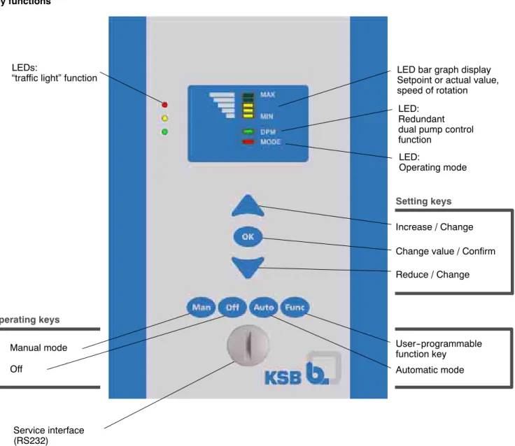
Standard control panel
Ident. No.: 47 121 274
The standard control panel features LEDs for the “traffic light” function, an LED bar graph display, keys and a service interface. With the standard control panel, users can:
D Change between the Manual, Off and Automatic operating modes
D Specify the setpoint
D Display the operating status, the motor speed and the sen-sor signal via LEDs
Key functions
LED bar graph display Setpoint or actual value, speed of rotation LEDs:
“traffic light” function
Service interface (RS232) Reduce / Change Increase / Change Setting keys Manual mode Off User--programmable function key Automatic mode Operating keys
Change value / Confirm LED:
Redundant dual pump control function
LED:
Operating mode
Fig. 1: PumpDrive standard control panel
A blanking plate (ident number: 47 106 619) that prevents intervention in the operating mode is available for safety-relevant ap-plications.
Graphical control panel
Ident. No.: 47 106 620 (Basic), 47 106 621 (Advanced)
The graphical control panel features a display screen, keys and a service interface.
The menu can be displayed on the graphical control panel screen and includes important information and commands for pump sys-tem operation.
Data can be displayed in plain text and parameters can be set. Key functions Display (plain text) Information Settings LEDs:
“traffic light” function
Operation Diagnosis Up / Increase Back / Cancel Service interface (RS 232)
Down / Reduce Confirm / Select
Help Navigation keys Function keys Manual mode Off User--programmable function key Automatic mode Operating keys 4070:0007
Menu structure
Operation menu level -- General operating data -- Motor parameters
-- Analog / digital inputs and outputs -- PumpDrive parameters
Diagnosis menu level
-- Messages (warnings and alerts) -- Alert history
Settings menu level -- Display language
-- Basic settings of FI / motor
-- Multiple pump operation (Advanced only) -- Protective functions for pump (Advanced only) -- Monitoring functions
Information menu level -- Serial number -- Software version
Accessories and optional equipment
Differential pressure sensors Type DE 30
Output signal 4 - 20 mA / three--wire system Supply voltage 15 - 30 V DC
Max. working resistance approx. 600 Ohm Max. ambient temperature 40°C
Measuring range
[bar] Gland / adapter Ident. number 1) 0 -- 2.0 Rc 3/8 01 109 558 0 -- 4.0 Rc 3/8 01 109 560 0 -- 6.0 Rc 3/8 01 109 562 0 -- 10.0 Rc 3/8 01 109 585 0 -- 2.0 Rc 1/2 01 111 305 0 -- 4.0 Rc 1/2 01 111 306 0 -- 6.0 Rc 1/2 01 111 307 0 -- 10.0 Rc 1/2 01 111 308
1) Complete with retaining plate, spiralled pipe sections and adapter
Output filter
In order to meet RFI suppression requirements to DIN 55011, the maximum cable lengths specified in the technical data must be observed. Output filters are required if longer cables are used.
Power
[kW] Max. cur-rent [A] L [mm] [mm]H [mm]B Ident. number 0.55 2.3 49 58 85 47 121 240 0.75 3.2 49 58 85 47 121 241 1.1 4.4 49 58 85 47 121 242 1.5 6 49 58 85 47 121 243 2.2 7.5 49 58 85 47 121 244 3 10 150 56 100 47 121 245 4 12.5 150 56 100 47 121 246 5.5 16.3 150 56 100 47 121 247 7.5 20.7 231 71 119 47 121 248 11 31.3 350 81 149 47 121 249 15 38.8 350 81 149 47 121 250 18.5 48.8 470 235 140 47 121 251 22 56.3 470 235 140 47 121 252 30 81.3 470 235 140 47 121 253 37 100 on
req.1) req.on1) req.on1) on req. 1)
45 116,3 on
req.1) req.on1) req.on1) on req. 1)
1) on req. = on request
Adapter for motor mounting
An adapter is only required if PumpDrive is to be mounted on the motor.
A suitable adapter (for Siemens or Cantoni motors) is to be se-lected based on the motor size and type of construction used.
Size
Si t Ident. number
Siemens motor Type of construction
V1 / V15 Type of constructionB3 71 47 117 519 47 117 519 80 47 117 520 On request. 90 47 117 521 47 117 522 100 47 117 511 47 117 515 112M 47 117 512 47 117 512 132S 47 117 513 47 117 513 160 47 117 514 47 117 514 180M 47 117 516 47 117 516 200L 47 117 517 47 117 517 225M 47 117 518 47 117 518 Size C t i M t Ident. number Cantoni Motor Type of construction V1 / V15
1.1 kW 47 121 167 3.0 kW 47 121 166 4.0 kW 47 121 165 7.5 kW 47 121 164 22 kW 47 121 163 37 kW 47 121 162
Adapter for wall and cabinet mounting
The adapter for PumpDrive models CM and WM, which is suit-able for both wall and cabinet mounting, is part of the KSB scope of supply as a standard.
PumpDrive
Size Ident. number
A + B 47 118 186
Note
Note LON module
Ident. No.: 47 106 600
The plug-on LON interface module is connected to an available on-site LON network.
The LON interface is equipped with a FTT-10A Transceiver (Free Topology Transceiver).
The following parameters, for example, can be transferred: -- Start
-- Stop -- Setpoint -- Actual value -- Speed
-- Pressure (if connected to sensor) -- Pump status
-- Pump fault or malfunction -- Operating hours
-- Energy input -- Pump input power
Further details and parameters can be found in the LON litera-ture for PumpDrive; refer to the Product Catalogue on the KSB web site.
The LON literature is based on the LONMARK Functional Profile Pump Controller V 1.0 - SFPTpumpController standard. If re-quired, the HVAC Profile 0.93 can be supported.
The LON interface is put into service on site.
PumpDrives used as single--pump drives can be monitored and controlled by a LON bus. A multiple pump configuration can only be monitored via LON; each PumpDrive then needs to be equipped with a LON module.
Profibus module Ident. No.: 47 106 601
The Profibus module is a Profibus DPV0 Slave.
The following parameters, for example, can be transferred: -- Start -- Stop -- Setpoint -- Actual value -- Speed -- Motor frequency -- Motor power -- Motor current -- Alerts -- Warnings
Further details and parameters can be found in the Profibus lit-erature for PumpDrive; refer to the Product Catalogue on the KSB web site.
The Profibus interface is put into service on site.
Single--pump drives and multiple pump configurations can be monitored and controlled with just one Profibus module. It is not possible to use additional, redundant Profibus modules.
Line chokes
The line input currents indicated in the project planning informa-tion are for orientainforma-tion purposes only; they refer to drive oper-ation at nominal rating. These currents may vary depending on the actual line impedance. In low--impedance mains, higher currents may occur.
To limit the line input current, external line chokes can be used alongside the line chokes already integrated in PumpDrive (in the power range up to and including 45 kW). These are to be selected in accordance with the table below.
Line chokes also reduce mains feedback and improve the power factor.
The scope of DIN EN 61000-3-2 must be taken into account.
PumpDrive Three-phase (3~) line choke: IP 00 enclosure; thermal class F; max. ambient temperature 40°C Size Power [kW] Ln [mH] In [A] Isat L [mm] W [mm] H [mm] Weight [kg] Ident. number
.. 000K55 .. 0.55 .. 000K75 .. 0.75 .. 001K10 .. 1.10 2 0 11 1 5 In 150 85 150 3 6 01 093 105 .. 001K50 .. 1.50 2.0 11 1.5 In 150 85 150 3.6 01 093 105 .. 002K20 .. 2.20 .. 004K00 .. 4.00 .. 005K50 .. 5.50 .. 007K50 .. 7.50 1.1 28 1.5 In 180 120 178 8.3 01 093 106 .. 011K00 .. 11.00 .. 015K00 .. 15.00 .. 018K50 .. 18.50 0.5 51 1.5 In 180 135 178 10.5 01 093 107 .. 022K00 .. 22.00 .. 030K00 .. 30.00 .. 037K00 .. 37.00 0.1 100 1.5 In 180 180 180 10.8 01 093 108 .. 045K00 .. 45.00 Service software Ident. No.: 47 121 211
A service software package, consisting of a CD--ROM, quick--ref-erence instructions and a special connection cable (MiniUSB-RS232) is available for comfortable parameterization of PumpDri-ves using a PC.
Dual pump module (DPM) Ident. No.: 47 121 257
The plug-in dual pump module is available as an accessory. In combination with the standard control panel it provides a cost--effi-cient solution for controlling redundant twin pumps, such as for example Etaline Z, or two identical pumps operating in parallel. Each drive must be equipped with its own DPM. The dual pump module cannot be used in combination with the graphical con-trol panel or the blanking plate.
KSB Aktiengesellschaft
67225 Frankenthal •Johann-Klein-Str. 9 • 67227 Frankenthal (Germany)
Tel. +49 6233 86-0 • Fax +49 6233 86-3401• www.ksb.de
4070.5/3 --10 23.04.2007 Te chni sche Ä nderungen bl ei ben vorbehal ten.
Dimensions and weights
Dimensions and weights refer exclusively to the PumpDrive without motor for motor mounting (MM), wall mounting (WM) and cabi-net mounting (CM).
4070:0001
PumpDrive
Sizep Power[kW] Dimensions Mounting holes Weight[kg]
Size [kW] A [mm] B [mm] C [mm] D [mm] E [mm] F [mm] G [mm] g [kg] .. 000K55 .. 0.55 .. 000K75 .. 0.75 7 A .. 001K10 .. 1.1 260 190 158 65 164 242 4xM6 7 A .. 001K50 .. 1.5 260 (312)1) 190 158 (168)1) 65 164 (164)1) 242 (292)1) 4xM69 mm .. 002K20 .. 2.2 ( ) ( ) ( ) ( ) 9 .. 003K00 .. 3 9 .. 004K00 .. 4 325 170 224 307 10 B .. 005K50 .. 5.5 325 (377)1) 250 170 (180)1) 65 224 (224)1) 307 (357)1) 4xM69 mm 10 5 .. 007K50 .. 7.5 (377) 1) 50 (180)1) 65 (224)1) (357)1) 9 mm 10.5 .. 011K00 .. 11 23 C .. 015K00 .. 15 420 320 235 125 283 396 4xM8 23 C .. 018K50 .. 18.5 420 (482)1) 320 235 (245)1) 125 283 (283)1) 396 (458)1) 4xM8 12 mm 30 .. 022K00 .. 22 ( ) ( ) ( ) ( ) 30 .. 030K00 .. 30 600 290 410 573 48 D .. 037K00 .. 37 600 (659)1) 450 290 (300)1) 125 410 (410)1) 573 (635)1) 4xM10 12 mm 48 .. 045K00 .. 45 (659) 1) (300)1) (410)1) (635)1) 12 mm 50
1)Dimensions given in parentheses apply to the wall-mounted (WM) and cabinet-mounted (CM) models only. All the dimensional data, i.e. both the sizes and the