DATA/FAX/VOICE AT Command Set
V.90 PCI Windows Modem (LHT)
Contents
Page
AT Commands Reference 2
AT Commands for Testing and Debugging 15
S-Registers Reference 17
AT FAX Command Set 24
AT Voice Commands 28
AT Commands Reference
AT commands are issued to the modem to control the modem's operation and software configuration. AT commands can only be entered while the modem is in command mode. The format for entering AT commands is:
TYPE: ATXn
where X is the AT command, and n is the specific value for that command. PRESS: Enter
Any command issued is acknowledged with a response in either text or numeric values known as result codes. Table 2 lists all the valid result codes.
For multiple AT commands in the same command line, the commands are executed in the order received from the DTE. Should execution of a command result in an error, or a character be not recognized as a valid command, execution is terminated, the re-mainder of the command line is ignored, and the ERROR result code is issued. Otherwise, if all commands execute correctly, only the result code associated with the last command shall be issue; result codes for preceding commands are suppressed.
In the following listing, all commands and command-values accepted by the modem are shown; any entries other than those shown cause the ERROR result code.
+++ Escape sequence
The escape sequence allows the modem to exit data mode and enter on-line command mode. While in on-line command mode, you may communicate directly to your modem using AT commands. Once you are finished, you may return to data mode using the ATO command.
A pause, the length which is set by the Escape Guard Time (S12), must be used after an escape sequence is issued. This pause prevents the modem from interpreting the escape sequence as data.
The value of the escape sequence character may be changed using Register S2.
A/ Repeat Last Command
This command repeats the last command string entered. Do not precede this command with an AT prefix or conclude it by pressing Enter.
A Answer Command
This command instructs the modem to go off-hook and answer an incoming call.
Bn Communication Standard Setting
This command determines CCITT vs. Bell standard.
B0: Selects CCITT V.22 mode when the modem is at 1200 bits/s. B1: Selects Bell 212A when the modem is at 1200 bits/s (default). B2: Unselects V23 reverse channel ( same as B3).
B3: Unselects V23 reverse channel ( same as B2). B15: Selects V.21 when the modem is at 300 bits/s.
B16: Selects Bell 103J when the modem is at 300 bits/s (default). Result Codes:
OK n = 0, 1, 15, 16
ERROR Otherwise
Cn Carrier Control
The modem will accept the C1 command without error in order to ensure backward compatibility with communications software that issues the C1 command. However, this modem does not support the C0 command. The C0 command may instruct some other mo-dems to not send carrier (i.e., it puts them in a receive-only mode).
C0: Transmit carrier always off. C1: Normal transmit carrier switching. Result Codes:
OK n = 1
ERROR Otherwise
Dn Dial
This command instructs the modem to begin the dialing sequence. The dial string (n, including modifiers and the telephone number) is entered after the ATD command.
A dial string can be up to 40 characters long. Any digit or symbol (0→9, *, #, A, B, C, D) may be dialed as touch-tone digits. Char-acters such as spaces, hyphens, and parentheses do not count, they are ignored by the modem and may be included in the dial string to enhance readability.
The following may be used as dial string modifiers:
L Redials last number. Should be the first character following ATD, ignored otherwise. The modem displays the dialing string in the following format: “Dialing…xxxxxxx” where “xxxxxxx” is the last number dialed.
P Pulse dialing. (e.g. ATDPxxx. Dialing set to pulse as default.)
T Touch-tone dialing (default). (e.g. ATDTxxx. Dialing set to tone as default.)
, Pause during dialing. Pause for time specified in Register S8 before processing the next character in the dial string. W Wait for dial tone. Modem waits for a second dial tone before processing the dial string.
@ Wait for quiet answer. Wait for five seconds of silence after dialing the number. If silence is not detected, the modem sends a NO ANSWER result code back to the user.
! Hook flash. Causes the modem to go on-hook for 0.5 seconds and then return to off-hook.
; Return to command mode. Causes the modem to return to command mode after dialing the number, without disconnecting the call.
^ Disable data calling tone transmission.
S=n Dial a telephone number previously stored using the &Zn=x command (see the &Zn=x command for further information). the range of n is 0—3.
$ Bong tone detection.
En Echo Command
This command controls whether or not the characters entered from your computer keyboard are echoed back to your monitor while the modem is in command mode.
E0: Disables echo to the computer.
E1: Enables echo to the computer (default). Result Codes:
OK n = 0, 1
ERROR Otherwise
Fn Online Data Character Echo Command
This command determines if the modem will echo data from the DTE. This modem does not support the F0 version of the com-mand. However, the modem will accept F1, which may be issued by older communication software, to assure backward compati-bility.
F0: Online data character echo enabled (NOT SUPPORTED, ERROR). F1: Online character echo disabled.
Result Codes:
OK n = 1
Hn Hook Control
This command instructs the modem to go on-hook to disconnect a call, or off-hook to make the phone line busy. H0: Modem goes on-hook (default).
H1: Modem goes off-hook. Result Codes:
OK n = 0, 1
ERROR Otherwise
In Request ID Information
This command displays specific product information about the modem. I0: Returns default speed and controller firmware version. (same as I3) I1: Calculates ROM checksum and displays it on the DTE (e.g., 12AB).
I2: Performs a ROM check and calculates and verifies the checksum displaying OK or ERROR. I3: Returns the default speed and the controller firmware version. (same as I0)
I4: Returns firmware version for data pump (e.g., 94).
I5: Returns the board ID: software version, hardware version, and country ID. I6 Response OK
I7 Response OK I8 Response OK
I9: Returns country code (e.g., North America Ver. 1). Result Codes:
OK n = 0—9
ERROR Otherwise
Ln Monitor Speaker Volume
This command sets speaker volume to low, medium, or high. L0: Selects lowest volume.
L1: Selects low volume.
L2: Selects medium volume (default). L3: Selects high volume.
Result Codes:
OK n = 0, 1, 2, 3
ERROR Otherwise
Mn Monitor Speaker Mode
This command turns the speaker on or off. M0: The speaker is off.
M1: The speaker is on until the modem detects the carrier signal (default). M2: The speaker is always on when modem is off-hook.
M3: The speaker is on until the carrier is detected, except while dialing. Result Codes:
OK n = 0, 1, 2, 3
ERROR Otherwise
Nn Modulation Handshake
This command controls whether or not the local modem performs a negotiated handshake at connection time with the remote mo-dem when the communication speed of the two momo-dems is different.
N0: When originating or answering, this is for handshake only at the communication standard specified by S37 and the ATB com-mand.
N1: When originating or answering, begin the handshake only at the communication standard specified by S37 and the ATB com-mand. During handshake, fallback to a lower speed may occur (default).
Result Codes:
OK n = 0, 1
ERROR Otherwise
On Return On-line to Data Mode
O0: Instructs the modem to exit on-line command mode and return to data mode (see AT Escape Sequence, +++). O1: This command issues a retrain before returning to on-line data mode.
O3: This command issues a rate re-negotiation before returning to on-line data mode. Result Codes:
OK n = 0, 1, 3
ERROR Otherwise
P Select Pulse Dialing
This command configures the modem for pulse (non-touch-tone) dialing. Dialed digits are pulsed until a T command or dial modifier is received. Tone dial is the default setting.
Qn Result Code Control
Result codes are informational messages sent from the modem and displayed on your monitor. Basic result codes are OK, CONNECT, RING, NO CARRIER, and ERROR. The ATQ command allows the user to turn result codes on or off.
Q0: Enables modem to send result codes to the computer (default). Q1: Disables modem from sending result codes to the computer. Result Codes:
OK n = 0, 1
ERROR Otherwise
T Select Tone Dialing
This command instructs the modem to send DTMF tones while dialing. Dialed digits are tone dialed until a P command or dial modi-fier is received. This is the default setting.
Vn DCE Response Format
This command controls whether result codes (including call progress and negotiation progress messages) are displayed as words or their numeric equivalents. (Numeric response codes are not supported by this modem.)
V1: Always displays result codes as text (default). Result Codes:
OK n = 1
ERROR Otherwise
ATV0 ATV1
Result Code Format <numeric code><CR> <CR><LF>
Wn Result Code Option
W0: CONNECT result code reports DTE speed. Disable protocol result codes. W1: CONNECT result code reports DTE speed. Enable protocol result codes.
W2: CONNECT result code reports DCE speed. Enable protocol result codes (default). Result Codes:
OK n = 0, 1, 2
ERROR Otherwise
Xn Result Code Selection and Call Progress Monitoring
This command enables tone detection options used in the dialing process. As these functions are chosen, the modem chip set’s re-sult codes are also affected. Therefore, this command is frequently used to control the modem chip set’s responses. The primary function of this control is to control the modem chip set’s call response capabilities.
Ext. Result Code Dial Tone Detect Busy Tone Detect
X0 Disable Disable Disable
X1 Enable Disable Disable
X2 Enable Enable Disable
X3 Enable Disable Enable
X4 Enable Enable Enable (default)
X5 Enable Enable Enable
X6 Enable Enable Enable
X7 Disable Enable Enable
Extended Result Codes
Disabled: Displays only the basic result codes OK, CONNECT, RING, NO CARRIER, and ERROR.
Enabled: Displays basic result codes, along with the connect message and the modem's data rate, and an indication of the modem's error correction and data compression operation.
Dial Tone Detect
Disabled: The modem dials a call regardless of whether it detects a dial tone. The period of time the modem waits before dialing is specified in register S6.
Enabled: The modem dials only upon detection of a dial tone, and disconnects the call if the dial tone is not detected within 10 seconds.
Busy Tone Detect
Disabled: The modem ignores any busy tones it receives. Enabled: The modem monitors for busy tones.
Result Codes:
OK n = 0, 1, 2, 3, 4, 5, 6, 7
Yn Long Space Disconnect
Long space disconnect is always disabled. Y0: Disable long space disconnect (default).
Y1: Enable long space disconnect. NOT SUPPORTED. Result Codes:
OK n = 0
ERROR Otherwise
Zn Recall Stored Profile
This command instructs the modem chip set to go on-hook and restore the profile saved by the last &W command. Either Z0 or Z1 restores the same single profile.
Result Codes:
OK n = 0, 1
ERROR Otherwise
&Bn V.32 Auto Retrain
This modem always auto retrains.
&B0: Disable V.32 auto retrain — NOT SUPPORTED. &B1: Enable V.32 auto retrain (default).
Result Codes:
OK n = 1
ERROR Otherwise
&Cn Data Carrier Detect (DCD) Control
Data Carrier Detect is a signal from the modem to your computer indicating that the carrier signal is being received from a remote modem. DCD normally turns off when the modem no longer detects the carrier signal.
&C0: The state of the carrier from the remote modem is ignored. DCD circuit is always on.
&C1: DCD turns on when the remote modem's carrier signal is detected, and off when the carrier signal is not detected (default).
Result Codes:
OK n = 0, 1
ERROR Otherwise
&Dn DTR Control
This command interprets how the modem responds to the state of the DTR signal and changes to the DTR signal.
&D0: Ignore. The modem ignores the true status of DTR and treats it as always on. This should only be used if your computer does not provide DTR to the modem.
&D1: If the DTR signal is not detected while in on-line data mode, the modem enters command mode, issues OK result code, and remains connected.
&D2: If the DTR signal is not detected while in on-line data mode, the modem disconnects (default). If this signal is not present, the modem will not answer or dial.
&D3: Monitor DTR signal when an on-to-off transition occurs, the modem performs a soft reset as if the ATZ command was re-ceived.
Result Codes:
OK n = 0, 1, 2, 3
&Fn Load Factory Settings
This command loads the configuration stored and programmed at the factory. This operation replaces all of the command options and the S-register settings in the active configuration with factory values.
&F0: Recall factory setting as active configuration (this is the only option supported by this modem).
&Gn V.22bis Guard Tone Control
This command determines which guard tone, if any, to transmit while transmitting in the high band (answer mode). This command is only used in V.22 and V.22bis mode. This option is not used in North America and is for international use only.
&G0: Guard tone disabled (default). &G1: Sets guard tone to 550 Hz. &G2: Sets guard tone to 1800 Hz. Result Codes:
OK n = 0, 1, 2
ERROR Otherwise
&Jn Auxiliary Relay option
&J0: The auxiliary relay is never closed. &J1: NOT SUPPORTED, responds ERROR. Result Codes:
OK n = 0
ERROR Otherwise
&Kn Local Flow Control Selection
&K0: Disable flow control. &K1: Reserved.
&K2: Reserved.
&K3: Enable RTS/CTS flow control (default). &K4: Enable XON/XOFF flow control. Result Codes:
OK n = 0, 3, 4
ERROR Otherwise
&Mn Asynchronous Communications Mode
&M0: Asynchronous mode (default). &M1: Reserved. &M2: Reserved. &M3: Reserved. &M4: Reserved. Result Codes: OK n = 0 ERROR Otherwise
&Pn Pulse Dial Make-to-Break Ratio Selection
This Command is effective only for Japan. &P0 39/61 make/break ratio, 10PPS
&PI 33/67 make/break ratio, 10PPS (default) &P2 33/67 make/break ratio, 20PPS Result Codes:
OK n = 0, 1, 2
ERROR Otherwise
&Qn Asynchronous Communications Mode
&Q0: Asynchronous Mode, buffered. Same as \N0.
&Q1: Reserved. &Q2: Reserved. &Q3: Reserved. &Q4: Reserved.
&Q5: Error Control Mode, buffered (default). Same as \N3.
&Q6: Asynchronous Mode, buffered. Same as \N0.
&Q7: Reserved.
&Q8: MNP error control mode. If an MNP error control protocol is not established, the modem will fallback according to the current user setting in S36.
&Q9: V.42 or MNP error control mode. If neither error control protocol is established, the modem will fallback according to the cur-rent user setting in S36.
Result Codes:
OK n = 0, 5, 6, 8, 9
ERROR Otherwise
&Sn Data Set Ready (DSR) Option
This command selects DSR action. &S0: DSR always ON (default).
&S1: DSR comes on when establishing a connection and goes off when the connection ends. Result Codes:
OK n = 0, 1
ERROR Otherwise
&V0 View Active Configuration and Stored Profile
This command is used to display the active profiles. &V0: View active file
For example:
Option Selection AT Cmd
Comm Standard Bell B
CommandCharEcho Enable E
Speaker Volume Medium L
Speaker Control OnUntilCarrier M
Result Codes Enable Q
Dialer Type Tone T/P
ResultCode Form Text V
ExtendResultCode Enabled X
DialTone Detect Enable X
BusyTone Detect Enable X
LSD Action Standard RS232 &C
DTR Action Standard RS232 &D
Option Selection AT Cmd
V22b Guard Tone Disable &G
Flow Control Hardware &K
Error Control Mode V42, MNP, Buffer \N
Data Compression V42bis/MNP5 %C
AutoAnswerRing# 0 S0
AT Escape Char 43 S2
CarriageReturn Char 13 S3
Linefeed Char 10 S4
Backspace Char 8 S5
Blind Dial Pause 2 sec S6
NoAnswer Timeout 50 sec S7
“,“ Pause Time 2 sec S8
Press any key to continue; ESC to quit.
Option Selection AT Cmd
No Carrier Disc 2000 msec S10
DTMF Dial Speed 95 msec S11
Escape GuardTime 1000 msec S12
Data Calling Tone Disabled S35
Line Rate 33600 S37
DSVD mode Disabled -SSE
Press any key to continue; ESC to quit. Stored Phone Numbers &Z0=
&Z1= 101 &Z2= &Z3= OK
&Wn Store Current Configuration
This command stores certain command options and S-register values into the modem’s nonvolatile memory. The ATZ command or a powerup reset of the modem restores this profile.
Result Codes:
OK n = 0
ERROR Otherwise
&Yn Select Stored Profile for Hard Reset
This command does not change the behavior of the modem but is included for compatibility with applications that issue the &Y0 command:
&Y0: Select stored profile 0 on powerup &Y1: ERROR.
Result Codes:
OK n = 0
ERROR Otherwise
&Zn=x Store Telephone Number
This command is used to store up to four dialing strings in the modem’s nonvolatile memory for later dialing. The format for the command is &Zn = ”stored number” where n is the location 03 to which the number should be written. The dial string may contain up to 40 characters. The ATDS = n command dials using the string stored in location n.
Result Codes:
OK n = 0, 1, 2, 3
ERROR Otherwise
\An Select Maximum MNP Block Size
The modem will operate an MNP error corrected link using a maximum block size controlled by the parameter supplied. \AO 64 characters.
\A1 128 characters. \A2 192 characters.
\A3 256 characters (DEFAULT). Result Codes:
OK n = 0, 1, 2, 3
ERROR Otherwise
\Bn Transmit Break to Remote
In non-error correction mode, the modem will transmit a break signal to the remote modem with a length in multiples of 100ms ac-cording to parameter specified. The command works in conjunction with the \K command.
\B1-\B9 Break length in 100ms units. (Default = 3.) (Non-error corrected mode only.) Result Codes:
OK If connected in data modem mode.
NO CARRIER If not connected or connected in fax modem mode.
\G Modem Port Flow Control
\G0: Returns an “OK” for compatibility (default). \G1: NOT SUPPORTED responds ERROR. Result Codes:
OK n = 0
ERROR Otherwise
\J Adjust Bits/s Rate Control
When this feature is enabled, the modem emulates the behavior of modems that force the DTE interface to the line speed. \J0: Turn off feature (default).
\J1: Turn on feature. Result Codes:
OK n = 0, 1
ERROR Otherwise
\Kn Break Control
Controls the response of the modem to a break received from the DTE or the remote modem or the \B command. The response is different in three separate states. The first state is where the modem receives a break from the DTE when the modem is operating in data transfer mode:
\K0 Enter on-line command mode, no break sent to the remote modem. \K1 Clear data buffers and send break to remote modem.
\K3 Send break to remote modem immediately. \K4 Same as 0.
\K5 Send break to remote modem in sequence with transmitted data. (Default.)
The second case is where the modem is in the on-line command state (waiting for AT commands) during a data connection, and the \B is received in order to send a break to the remote modem:
\K0 Clear data buffers and send break to remote modem.
\K1 Clear data buffers and send break to remote modem. (Same as 0.) \K2 Send break to remote modem immediately.
\K3 Send break to remote modem immediately. (Same as 2.) \K4 Send break to remote modem in sequence with data.
\K5 Send break to remote modem in sequence with data. (Same as 4.) (Default.) The third case is where a break is received from a remote modem during a connection:
\K0 Clear data buffers and send break to the DTE.
\K1 Clear data buffers and send break to the DTE. (Same as 0.) \K2 Send a break immediately to DTE.
\K3 Send a break immediately to DTE. (Same as 2.) \K4 Send a break in sequence with received data to DTE.
\K5 Send a break in sequence with received data to DTE. (Same as 4.) (Default.) Result Codes:
OK n = 0,1, 2, 3, 4, 5
ERROR Otherwise
\Nn Error Control Mode Selection
This command determines the type of error control used by the modem when sending or receiving data. \N0: Buffer mode. No error control (same as &Q6).
\N1: Direct mode.
\N2: MNP or disconnect mode. The modem attempts to connect in MNP 2-4 error control procedure. If this fails, the modem discon-nects. This is also known as MNP reliable mode.
\N3: V.42, MNP, or buffer (default). The modem attempts to connect in V.42 error control mode. If this fails, the modem attempts to connect in MNP mode. If this fails, the modem connects in buffer mode and continues operation. This is also known as V.42/ MNP auto reliable mode (same as &Q5).
\N4: V.42 or disconnect. The modem attempts to connect in V.42 error control mode. If this fails, the call will be disconnected. \N5: V.42 MNP or buffer (same as \N3)
\N7: V.42. MNP or buffer (same as \N3). Result Codes:
OK n = 0, 1, 2, 3, 4, 5, 7
\Q Local Flow Control Selection
\Q0: Disable flow control. Same as &K0.
\Q1: XON/XOFF software flow control. Same as &K4.
\Q2: CTS-only flow control. This is not supported, and the response is ERROR. \Q3: RTS/CTS to DTE (default). Same as &K3.
Result Codes:
OK n = 0, 1, 3
ERROR Otherwise
\Rn Ring indicator signal off after the telephone call is answered (Compatibility command)
Result Codes:
OK n = 0
ERROR Otherwise
\Tn Inactivity Timer
This command specifies the length of time (in minutes) that the modem will wait before disconnecting when no data is sent or re-ceived. A setting of zero disables the timer. Alternatively, this timer may be specified in register S30. This function is only applicable to buffer mode.
Result Codes:
OK n = 0 → 255
ERROR Otherwise
\Vn Protocol Result Code
\V0: Disable protocol result code \V1: Enable protocol result code \V2: Enable protocol result code Result Codes:
OK n = 0, 1, 2
ERROR Otherwise
\Xn XON/XOFF Pass Through
\X0 Modem processes XON/XOFF flow control characters locally (DEFAULT). \X1 Modem processes and pass XON/XOFF flow control characters.
Result Codes:
OK n = 0, 1
ERROR Otherwise
-Cn Data Calling Tone
Data Calling Tone is a tone of certain frequency and cadence as specified in V.25 which allows remote Data/FAX/Voice discrimina-tion. The frequency is 1300 Hz with a cadence of .5 s on and 2 s off.
-CO: Disabled (default). -C1: Enabled.
Result Codes:
OK n = 0, 1
ERROR Otherwise
-V90=x V.90 Downstream Rate and Control
Use this command to enable/disable V.90 connection and control V.90 connection rate. The command syntax is AT-V90=x. Where x is a value from the list below.
AT-V90=x Downstream Rate
0 V.90 disabled 1 Auto Rate (default) 2 28000 bits / s 3 29333 bits / s 4 30666 bits / s 5 32000 bits / s
6 33333 bits / s 7 34666 bits / s 8 36000 bits / s 9 37333 bits / s 10 38666 bits / s 11 40000 bits / s 12 41333 bits / s 13 42666 bits / s 14 44000 bits / s 15 45333 bits / s 16 46666 bits / s 17 48000 bits / s 18 49333 bits / s 19 50666 bits / s 20 52000 bits / s 21 53333 bits / s Additional Commands
AT-V90? Shows the current value and displays the selected range.
AT-V90=? Shows the range of values (0-21).
%B View Numbers in Blacklist
If blacklisting is in effect, this command displays the numbers for which the last call attempted in the past two hours failed. The ERROR result code appears in countries that do not require blacklisting.
%Cn Enable/Disable Data Compression
Enables or disables data compression negotiation on an error corrected link. %C0 Disables data compression
%C1 Enables both V.42 bis and MNP 5 data compression Result Codes:
OK n = 0, 1
AT Commands for Testing and Debugging
The following commands are to be used for testing and debugging only and are not meant for general use.
&&C Write to/Read from DSP Register
AT&&C<loc>,<val> writes the value <val> to DSP register at location <loc>. AT&&C<loc> reads from location <loc>.
&&L Line-to-Line Loopback
This command provides a loopback for line-to-line.
&&R Write to/Read from DSP RAM Location
AT&&R<loc>,<val> writes the value <val> to DSP RAM location <loc>. AT&&R<loc> reads from location <loc>.
&Tn Self-Test Commands
This command allows the user to perform diagnostic tests on the modem. These tests can help to isolate problems when experi-encing periodic data loss or random errors.
&T0: Abort. Stops any test in progress.
&T1: Local analog loop. This test verifies modem operation, as well as the connection between the modem and computer. Any data entered at the local DTE is modulated, then demodulated, and returned to the local DTE. To work properly, the modem must be off-line.
&T3: Local digital loopback test.
&T6: Remote digital loopback test. This test can verify the integrity of the local modem, the communications link, and the remote modem. Any data entered at the local DTE is sent to, and returned from, the remote modem. To work properly, the modems must be on-line with error control disabled.
Result Codes:
OK n = 0
CONNECT n = 1, 3, 6
ERROR Otherwise
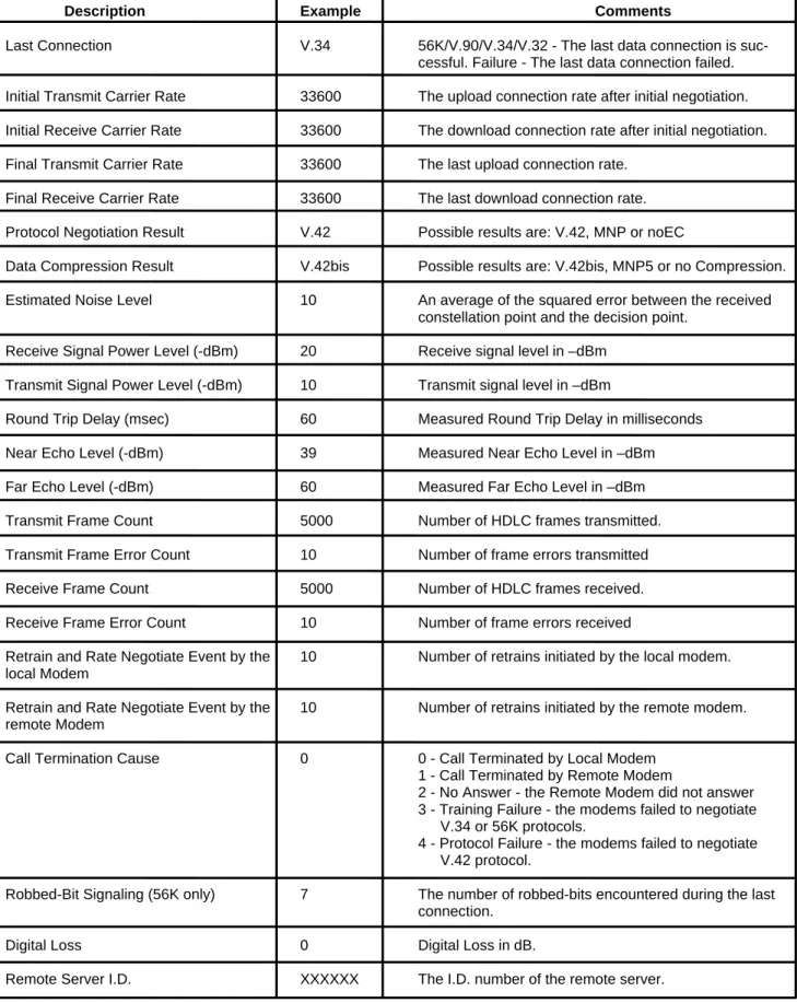
ATI11 Display Diagnostic Information for the last modem connection
The “ATI11” command displays the following diagnostic information for the last modem connection. A value of “NA” will be displayed if that parameter is not applicable for that connection (See Table 1 on the next page).
Table 1. Diagnostic Information
Description Example Comments
Last Connection V.34 56K/V.90/V.34/V.32 - The last data connection is suc-cessful. Failure - The last data connection failed. Initial Transmit Carrier Rate 33600 The upload connection rate after initial negotiation. Initial Receive Carrier Rate 33600 The download connection rate after initial negotiation. Final Transmit Carrier Rate 33600 The last upload connection rate.
Final Receive Carrier Rate 33600 The last download connection rate. Protocol Negotiation Result V.42 Possible results are: V.42, MNP or noEC
Data Compression Result V.42bis Possible results are: V.42bis, MNP5 or no Compression. Estimated Noise Level 10 An average of the squared error between the received
constellation point and the decision point. Receive Signal Power Level (-dBm) 20 Receive signal level in –dBm
Transmit Signal Power Level (-dBm) 10 Transmit signal level in –dBm
Round Trip Delay (msec) 60 Measured Round Trip Delay in milliseconds
Near Echo Level (-dBm) 39 Measured Near Echo Level in –dBm
Far Echo Level (-dBm) 60 Measured Far Echo Level in –dBm
Transmit Frame Count 5000 Number of HDLC frames transmitted.
Transmit Frame Error Count 10 Number of frame errors transmitted
Receive Frame Count 5000 Number of HDLC frames received.
Receive Frame Error Count 10 Number of frame errors received
Retrain and Rate Negotiate Event by the 10 Number of retrains initiated by the local modem. local Modem
Retrain and Rate Negotiate Event by the 10 Number of retrains initiated by the remote modem. remote Modem
Call Termination Cause 0 0 - Call Terminated by Local Modem
1 - Call Terminated by Remote Modem
2 - No Answer - the Remote Modem did not answer 3 - Training Failure - the modems failed to negotiate
V.34 or 56K protocols.
4 - Protocol Failure - the modems failed to negotiate V.42 protocol.
Robbed-Bit Signaling (56K only) 7 The number of robbed-bits encountered during the last connection.
Digital Loss 0 Digital Loss in dB.
S-Registers Reference
S-Registers DefinitionsS-registers generally affect how the AT commands perform. Contents of the registers can be displayed or modified when the mo-dem is in command mode.
To display the value of an S-register:
TYPE: ATSn?
where n is the register number.
PRESS: Enter
To modify the value of an S-register:
TYPE: ATSn = r
where n is the register number, and r is the new register value.
PRESS: Enter
S0 Auto Answer Ring Number
This register determines the number of rings the modem will count before automatically answering a call. Enter 0 (zero) if you do not want the modem to automatically answer at all. When disabled, the modem can only answer with an ATA command.
Range: 0→255
Default: 0
Units: rings
S1 Ring Counter
This register, Ring Counter, is read only. The value of S1 is incremented with each ring. If no rings occur over a six second interval, this register is cleared.
Range: 0→255
Default: 0
Units: rings
S2 AT Escape Character (user defined)
This register determines the ASCII valued used for an escape sequence. The default is the + character. The escape sequence al-lows the modem to exit data mode and enter command mode when on-line. Values greater than 127 disable the escape sequence.
Range: 0→255
Default: 43
Units: ASCII
S3 Command Line Termination Character (user defined)
This register determines the ASCII values as the carriage return character. This character is used to end command lines and result codes.
Range: 0→127, ASCII decimal Default: 13 (carriage return)
S4 Response Formatting Character (user defined)
This register determines the ASCII value used as the line feed character. The modem uses a line feed character in command mode when it responds to the computer.
Range: 0→127, ASCII decimal Default: 10 (line feed)
Units: ASCII
S5 Command Line Editing Character (user defined)
This register sets the character recognized as a backspace and pertains to asynchronous only. The modem will not recognize the backspace character if it is set to a value that is greater than 32 ASCII. This character can be used to edit a command line. When the echo command is enabled, the modem echoes back to the local DTE the backspace character, an ASCII space character, and a second backspace character. This means a total of three characters are transmitted each time the modem processes the back-space character.
Range: 0→32, 127 Default: 8 (backspace)
Units: ASCII
S6 Wait Before Dialing
This register sets the length of time, in seconds, that the modem must wait (pause) after going off-hook before dialing the first digit of the telephone number. The modem always pauses for a minimum of two seconds, even if the value of S6 is less than two sec-onds. The wait for dial tone call progress feature (W dial modifier in the dial string) will override the value in register S6. This opera-tion, however, may be affected by some ATX options according to country restrictions.
Range: 2→65
Default: 2
Units: seconds
S7 Connection Completion Time-Out
This register sets the time, in seconds, that the modem must wait before hanging up because carrier is not detected. The timer is started when the modem finishes dialing (originate), or goes off-hook (answer). In originate mode, the timer is reset upon detection of an answer tone if allowed by country restriction. The timer also specifies the wait for silence time for the @ dial modifier in sec-onds. S7 is not associated with the W dial modifier.
Range: 1→255
Default: 50
Units: seconds
S8 Comma Dial Modifier Time
This register sets the time, in seconds, that the modem must pause when it encounters a comma (,) in the dial command string.
Range: 0→65
Default: 2
Units: seconds
S10 Automatic Disconnect Delay
This register sets the length of time, in tenths of a second, that the modem waits before hanging up after a loss of carrier. This al-lows for a temporary carrier loss without causing the local modem to disconnect. The actual interval the modem waits before dis-connecting is the value in register S10.
Range: 1→254
Default: 20
S11 DTMF Dialing Speed
This register determines the dialing speed which is prefixed for each country.
Range: 50→150
Default: 95
Units: 0.001 seconds
S12 Escape Guard Time
This register sets the value (in 20 ms increments) for the required pause after the escape sequence (default 1 s).
Range: 0→255
Default: 50
Units: 0.02 seconds
S14 General Bit Mapped Options Status
Indicates the status of command options. Only bit 2 and bit 5 are used, read only. Bit 3 Result codes (Vn)
1 = Verbose (Vl) (Default) Bit 6 Pulse dial PPS selection (&Pn)
0 = 10 PPS (&p0, &p1) (Default) 1 = 20 PPS (&p2)
Default: 8 (00001000b)
S21 V.24/General Bit Mapped Options Status
Indicates the status of command options. Only bits 3, 4 and 5 are used, read only. Bits 3-4 DTR behavior (&Dn)
0 = &D0 selected 1 = &D1 selected
2 = &D2 selected (Default) 3 = &D3 selected
Bit 5 DCD behavior (&Cn) 0 = &C0 selected
1 = &C1 selected (Default) Default: 48 (00110000b)
S22 Results Bit Mapped Options Status
Indicates the status of command options. Only bits 4, 5 and 6 are used, read only. Bits 4-6 result codes (Xn)
0 = X0 selected 4 = X1 selected 5 = X2 selected 6 = X3 selected
7 = X4 selected (Default)
Bit 7 Pulse dial make/break ratio (&Pn)
0 = 33/67 make/break ratio (&P1, &P2) (Default) 1 = 39/61 make/break ratio (&P0)
S24 Timer to Control Sleep Mode
This command displays the number of seconds of inactivity (no characters sent from the DTE, no RING) in the off-line command state before the modem places itself into standby mode. A value of zero prevents standby mode.
Note: If a number between 1 and 4 is entered for this register, it will set the value to 5, and the inactivity before standby will be 5 seconds. This is done for compatibility with previous products which allowed time-outs down to 1 s.
Range: 0, 5→255 Default: 10
S28 V.34 Modulation Enable/Disable
This register enables/disables V.34 modulation. 0 = disabled, 1→255 = enabled, Range: 0→255
Default: 1
S30 Inactivity Timer
S30 specifies the length of time (in minutes) that the modem will wait before disconnecting when no data is sent or received. This function is only applicable to buffer mode.
Range: 0→255 Default: 0 Units: minutes
S32 Synthetic Ring Volume
This register specifies a synthetic ring volume in dB with an implied minus sign. Range:
Default: 16
S33 Synthetic Ring Frequency
This register specifies a synthetic ring frequency. Valid ranges are 0-5, with 0= disabled and 1-5 corresponding to 5 ring frequen-cies.
Range: 0-5 Default: 0
S35 Data Calling Tone
Data Calling Tone is a tone of certain frequency and cadence as specified in V.25 which allows remote Data/FAX/Voice discrimina-tion. The frequency is 1300 Hz with a cadence of .5 s on and 2 s off.
0 = disabled, 1 = enabled, Range: 0→1
Default: 0
S36 Negotiation Fallback (default 7)
This register specifies the action to take in the event of negotiation failure when error control is selected. S36 = 0, 2 Hang up.
S36 = 1, 3 Fall back to an asynchronous connection. S36 = 4, 6 Attempt MNP. If MNP fails, hang up.
S37 Dial Line Rate (default 0)
S37 = 0 maximum modem speed (default). S37 = 1 reserved
S37 = 2 1200 bits/s and 75 bits/s S37 = 3 300 bits/s S37 = 4 reserved S37 = 5 1200 bits/s S37 = 6 2400 bits/s S37 = 7 4800 bits/s S37 = 8 7200 bits/s S37 = 9 9600 bits/s S37 = 10 12000 bits/s S37 = 11 14400 bits/s S37 = 12 16800 bits/s S37 = 13 19200 bits/s S37 = 14 21600 bits/s S37 = 15 24000 bits/s S37 = 16 26400 bits/s S37 = 17 28800 bits/s S37 = 18 31200 bits/s S37 = 19 33600 bits/s
S38 K56flex Dial Line Rate (default 1)
There are 2 S-registers for K56flex connections. S38 sets the maximum 56K downstream speed that the modem attempts to con-nect. To disable K56flex, set S38 to 0. S37 register is used to control the upstream V.34 rate. ( ref. V.34 Data/Fax Document ). Use the AT-V90=x command to control V.90 connections.
S38 = 0 56K disabled
S38 = 1 56K enabled - automatic speed selection - maximum modem speed (default). S38 = 2 32000 bits / s S38 = 3 34000 bits / s S38 = 4 36000 bits / s S38 = 5 38000 bits / s S38 = 6 40000 bits / s S38 = 7 42000 bits / s S38 = 8 44000 bits / s S38 = 9 46000 bits / s S38 = 10 48000 bits / s S38 = 11 50000 bits / s S38 = 12 52000 bits / s S38 = 13 54000 bits / s S38 = 14 56000 bits / s
S40 ETC Startup Autorating (default 0, range 0→2)
S20=0 Startup with normal autorating. S20=1 Startup at initial rate of 4800 or below. S20=2 Startup at initial rate of 9600 or below.
Range: 0→2
Default: 0
S42 Auto Rate (default 1, range 0→1)
This command is used for testing and debugging only.
V.32bis and V.22bis auto rate is disabled. Retrain operation is disabled or enabled in data mode, and fallback is disabled in data mode.
0 = auto rate disabled, 1 = enabled.
Range: 0→1
S43 Auto Mode (default 1, range 0→1)
This command is used for testing and debugging only. V.32bis startup auto mode operation disabled.
0 = auto mode disabled, 1 = enabled.
Range: 0→1
Default: 1
S48 LAPM Error Control and Feature Negotiation (default 7)
S48 = 7 Negotiation enabled.
S 48 = 128 Negotiation disabled; forces immediate fallback options specified in S36.
The following chart lists the S36 and S48 configuration settings necessary to negotiate certain types of connections:
S48=7 S48 =128
S36 = 0, 2 LAPM or hangup do not use
S36 = 1, 3 LAPM or async async
S36 = 4, 6 LPAM, MNP, or hangup MNP or hangup S36 = 5, 7 LAPM, MNP, or async MNP or async
S89 Timer to Control Sleep Mode
This command displays the number of seconds of inactivity (no characters sent from the DTE, no RING) in the off-line command state before the modem places itself into standby mode. A value of zero prevents standby mode.
Note: If a number between 1 and 4 is entered for this register, it will set the value to 5, and the inactivity before standby will be 5 seconds. This is done for compatibility with previous products which allowed time-outs down to 1 s.
Range: 0, 5→255
Default: 10
S90 Local Phone Status
This register tells the status of the local phone. It is read only. 0 = local phone on-hook
1 = local phone off-hook
S91 Line Transmit Level
This register is effective only for Japan. It specifies the line transmit level in dB with an implied minus sign.
Range: 6→15
Default: 15
Units: 1 dB
S92 Direct Connect Transmit Level (default 20)
Table 2. The Result Code Summary
Result Code Description
OK Command executed
CONNECT Modem connected to line RING A ring signal has been detected
NO CARRIER Modem lost carrier signal, or does not detect carrier signal, or does not detect answer tone. ERROR invalid command
CONNECT 1200 EC* Connection at 1200 bits/s NO DIALTONE No dial tone detected BUSY Busy signal detected NO ANSWER No quiet answer CONNECT 2400 EC* Connection at 2400 bits/s CONNECT 4800 EC* Connection at 4800 bits/s CONNECT 9600 EC* Connection at 9600 bits/s CONNECT 14400 EC* Connection at 14400 bits/s CONNECT 19200 EC* Connection at 19200 bits/s CONNECT 7200 EC* Connection at 7200 bits/s CONNECT 12000 EC* Connection at 12000 bits/s CONNECT 16800 EC* Connection at 16800 bits/s CONNECT 300 EC* Connection at 300 bits/s CONNECT 21600 EC* Connection at 21600 bits/s CONNECT 24000 EC* Connection at 24000 bits/s CONNECT 26400 EC* Connection at 26400 bits/s CONNECT 28800 EC* Connection at 28800 bits/s CONNECT 31200 EC* Connection at 31200 bits/s CONNECT 33600 EC* Connection at 33600 bits/s CONNECT 38400 EC* Connection at 38400 bits/s CONNECT 57600 EC* Connection at 57600 bits/s CONNECT 115200 EC Connection at 115200 bits/s
DELAYED Delay is in effect for the dialed number BLACKLISTED Dialed number is blacklisted
BLACKLIST FULL Blacklist is full
CONNECT 32000 EC* Connection at 32000 bits/s, 56K rate CONNECT 34000 EC* Connection at 34000 bits/s, 56K rate CONNECT 36000 EC* Connection at 36000 bits/s, 56K rate CONNECT 38000 EC* Connection at 38000 bits/s, 56K rate CONNECT 40000 EC* Connection at 40000 bits/s, 56K rate CONNECT 42000 EC* Connection at 42000 bits/s, 56K rate CONNECT 44000 EC* Connection at 44000 bits/s, 56K rate CONNECT 46000 EC* Connection at 46000 bits/s, 56K rate CONNECT 48000 EC* Connection at 48000 bits/s, 56K rate CONNECT 50000 EC* Connection at 50000 bits/s, 56K rate CONNECT 52000 EC* Connection at 52000 bits/s, 56K rate CONNECT 54000 EC* Connection at 54000 bits/s, 56K rate CONNECT 56000 EC* Connection at 56000 bits/s, 56K rate CONNECT 58000 EC* Connection at 58000 bits/s, 56K rate CONNECT 60000 EC* Connection at 60000 bits/s, 56K rate CONNECT 28000 EC* Connection at 28000 bits/s, V.90 rate CONNECT 29333 EC* Connection at 29333 bits/s, V.90 rate CONNECT 30666 EC* Connection at 30666 bits/s, V.90 rate CONNECT 32000 EC* Connection at 32000 bits/s, V.90 rate CONNECT 33333 EC* Connection at 33333 bits/s, V.90 rate CONNECT 34666 EC* Connection at 34666 bits/s, V.90 rate CONNECT 36000 EC* Connection at 36000 bits/s, V.90 rate CONNECT 37333 EC* Connection at 37333 bits/s, V.90 rate CONNECT 38666 EC* Connection at 38666 bits/s, V.90 rate CONNECT 40000 EC* Connection at 40000 bits/s, V.90 rate CONNECT 41333 EC* Connection at 41333 bits/s, V.90 rate CONNECT 42666 EC* Connection at 42666 bits/s, V.90 rate CONNECT 44000 EC* Connection at 44000 bits/s, V.90 rate CONNECT 45333 EC* Connection at 45333 bits/s, V.90 rate CONNECT 46666 EC* Connection at 46666 bits/s, V.90 rate CONNECT 48000 EC* Connection at 48000 bits/s, V.90 rate CONNECT 49333 EC* Connection at 49333 bits/s, V.90 rate CONNECT 50666 EC* Connection at 50666 bits/s, V.90 rate CONNECT 52000 EC* Connection at 52000 bits/s, V.90 rate CONNECT 53333 EC* Connection at 53333 bits/s, V.90 rate
• EC only appears when the Extended Result Codes configuration option is enabled. EC is replaced by one of the following symbols, depending upon the error con-trol method used:
V42bis—V.42 error control and V.42bis data compression. V42—V.42 error control only.
MNP 5— MNP class 4 error control and MNP class 5 data compression. MNP 4— MNP class 4 error control only.
AT FAX Command Set
Class 1 FAX Commands
The HSM Data/FAX Complete Chip Set supports FAX commands conforming to EIA standard 578. These commands are given here with short descriptions; complete explanations are given in the standard, available from the Electronic Industry Association.
The AT FAX Command Set Summary
Command Description
+FCLASS? Service class indication
+FCLASS = ? Service class capabilities
+FCLASS = n Service class selection
+FTS = <n> Transmission silence
+FRS = <n> Receive silence
+FTM = <m> Transmit FAX data with <m> carrier +FRM = <m> Receive FAX data with <m> carrier +FTH = <m> Transmit HDLC data with <m> carrier +FRH = <m> Receive HDLC data with <m> carrier
+FTM = ? Transmit FAX modulation
+FRM = ? Receive FAX modulation
+FTH = ? Transmit HDLC Data modulation
+FRH = ? Receive HDLC Data modulation
+FMI = ? Manufacturer Identification
+FMM = ? Product Identification
+FMR = ? Version/Revision Information
+FCLASS? Service Class Indication
This command causes the modem to display the current setting. The modem can operate either as a Class 0 data modem or a class 1 FAX modem.
Typical responses:
+FCLASS? 000 if in data mode; 001 if in FAX class 1, 008 if in voice mode.
+FCLASS=? Service Class Capabilities
This command causes the modem to display the classes it supports. Typical responses:
+FCLASS=n Service Class Selection
This command sets the modem for class n operation, where n is either a 0 or 1. Parameters: 0, 1, 8
Default: 0
Command options:
+FCLASS = 0 Select data mode. +FCLASS = 1 Select Facsimile Class 1. +FCLASS = 8 Select voice mode.
+FTS=<n> Transmission Silence
This command causes the modem to stop transmitting data and pause for 10 * n ms. At the end of this period, the modem then re-sponds OK. You can specify any number from 0 through 255 as the value of n; for example, a value of 5 specifies a period of 50ms.
n = 0→255 (10 ms intervals)
+FRS=<n> Receive Silence
This command causes the modem to listen and wait for a 10 * n ms period of silence on the line. At the end of this period, the mo-dem then responds OK. You can specify any number from 0 through 255 as the value of n; for example, a value of 5 specifies a pe-riod of 50 ms.
n = 0→255 (10 ms intervals)
+FTM=<m> Transmit FAX Data with <m> Carrier
This command causes the modem to transmit data at the modulation specified by <m>. The following table shows the values you can enter for this command and the meaning of those values.
Command Option Modulation Speed (bits/s)
+FTM=3 V.21Channel 2300 +FTM=24 V.27ter 2400 +FTM=48 V.27ter 4800 +FTM=72 V.29 7200 +FTM=96 V.29 9600 +FTM=73 V.17 7200 +FTM=74 V.17 (short train) 7200 +FTM=97 V.17 9600 +FTM=98 V.17 (short train) 9600 +FTM=121 V.17 12000 +FTM=122 V.17 (short train) 12000 +FTM=145 V.17 14400 +FTM=146 V.17 (short train) 14400
+FRM=<m> Receive FAX Data with <m> Carrier
This command causes the modem to receive data at the modulation specified by <m>.
Command Option Modulation Speed (bits/s)
+FRM=3 V.21 Channel 2 300 +FRM=24 V.27ter 2400 +FRM=48 V.27ter 4800 +FRM=72 V.29 7200 +FRM=96 V.29 9600 +FRM=73 V.17 7200 +FRM=74 V.17 (short train) 7200 +FRM=97 V.17 9600 +FRM=98 V.17 (short train) 9600 +FRM=121 V.17 12000 +FRM=122 V.17 (short train) 12000 +FRM=145 V.17 14400 +FRM=146 V.17 (short train) 14400
+FTH=<m> Transmit HDLC Data with <m> Carrier
This command causes the modem to transmit data framed in the HDLC protocol at the modulation specified by <m>.
Command Option Modulation Speed (bits/s)
+FTH=3 V.21 Channel 2 300 +FTH=24 V.27ter 2400 +FTH=48 V.27ter 4800 +FTH=72 V.29 7200 +FTH=96 V.29 9600 +FTH=73 V.17 7200 +FTH=74 V.17 (short train) 7200 +FTH=97 V.17 9600 +FTH=98 V.17 (short train) 9600 +FTH=121 V.17 12000 +FTH=122 V.17 (short train) 12000 +FTH=145 V.17 14400 +FTH=146 V.17 (short train) 14400
+FRH=<m> Receive HDLC Data with <m> Carrier
This command causes the modem to receive data framed in the HDLC protocol at the modulation specified by <m>.
Command Option Modulation Speed (bits/s)
+FRH=3 V.21 Channel 2 300 +FRH=24 V.27ter 2400 +FRH=48 V.27ter 4800 +FRH=72 V.29 7200 +FRH=96 V.29 9600 +FRH=73 V.17 7200 +FRH=74 V.17 (short train) 7200 +FRH=97 V.17 9600 +FRH=98 V.17 (short train) 9600 +FRH=121 V.17 12000 +FRH=122 V.17 (short train) 12000 +FRH=145 V.17 14400 +FRH=146 V.17 (short train) 14400
Manufacturer Identification (+FMI?)
Read Syntax: AT+FMI?
This parameter reports the manufacturer identification. Typically, the text consists of the name of the manufacturer, but the manu-facturer may choose to provide more information (e.g., address, telephone number for customer service, etc.). The maximum text length is 80 characters. It is preferred that the first eight characters be unique.
Product Identification (+FMM?)
Read Syntax: AT+FMM?
This parameter reports product identification. Typically, the text consists of the name of the product. but the manufacturer may choose to provide more information. The maximum text length is 80 characters. It is preferred that the first eight characters be unique.
Version / Revision Information (+FMR?)
Read Syntax: AT+FMR?
This parameter reports the version, revision level, or other pertinent information for the device. Typically, the text consists of the version of the product, but the manufacturer may choose to provide more information (e.g., date code). The maximum text length is 80 characters. It is preferred that the first eight characters be unique.
Response Format (ATV)
Write Syntax: ATV<value>
Valid Values: 1 Default Value: 1
ATV1 verbose
This modem supports only text (verbose) result codes.
ATV0 (not supported) ATV1
Result Code Format <CR><LF>
<verbose code><CR><LF>
AT Voice Command Set
The AT Voice Command set follows a modified IS-101 architecture. The commands are sent through the COM port, but the data path is sent either through the COM port or through a DMA channel using the wave driver.
General AT Voice Commands
AT+FCLASS=8 Enter Voice Mode
The command AT+FCLASS=8 puts the modem in voice mode. TAD modes are placed under the more general heading of voice mode, and use a particular subset of voice mode commands to implement its respective features and functions. The modem con-troller will maintain the overall state of the system so as to know when voice commands are issued in the context of using the TAD or other voice contexts.
• AT+FCLASS? Returns the current DCE mode
• AT+FCLASS=? Queries the DCE for the range of modes supported DCE returns: 0, 1, 8 (data, FAX, voice)
AT+VIP Initialize Voice Parameters
The command AT+VIP causes the modem to initialize all the voice parameters to their default values. The command has no effect on the +FCLASS setting.
AT+FMI?, AT+FMM?, AT+FMR DCE Identification Commands
This command will enable DCE identification. • +FMI? = Report manufacturer ID
• +FMM? = Report product identification (model) • +FMR? = Report version or revision level
AT+VIT = <Timer> DTE/DCE Inactivity Timer
This command sets the DCE’s value for the DTE/DCE inactivity timer. The units are in one seconds. AT+VIT? Returns the current value of the timer
AT+VIT=? Queries the DCE for the range of supported values
AT+VEM=<mask> Event Reporting and Masking
The DTE can use this command to disable an event report regardless of the DCE state, or of the analog signal source or destination configuration. Mask is Bits 0→33 (i.e., FFFFFFFFC). See the IS-101 specification for defined bit values.
AT+VEM? Returns the current values of the mask
AT+VEM=? Queries the DCE for the range of supported service level events
AT+FMI?, AT+FMM?, AT+FMR DCE Identification Commands
This command will enable DCE identification. +FMI? = Report manufacturer ID
+FMM? = Report product identification (model) +FMR? = Report version or revision level
AT+VIT = <Timer> DTE/DCE Inactivity Timer
This command sets the DCE’s value for the DTE/DCE inactivity timer. The units are in one seconds. AT+VIT? Returns the current value of the timer
AT+VIT=? Queries the DCE for the range of supported values
AT+VNH = <Hook> Automatic Hang-up Control
This command causes the DCE to enable or disable automatic hangups in the data and facsimile modes. See the ISO-101 specifi-cation for the detailed description of this command and its interaction with the +FCLASS and ATH commands.
<hook> = 0 The DCE retains automatic hangups (which is the way in the other non-voice modes).
<hook> = 2 The DCE disables automatic hangups in the other non-voice modes. The DTE only performs a logical hang-up (returns the “OK” result code).
AT+VNH? Returns the current value AT+VNH=? Returns the supported values
AT Voice Command Set Related to Telephone Answering Device
AT+VTD=<dur> Beep Tone Duration Timer
This command sets the default duration for DTMF/tone generation in 0.01 s increments. For DTMF digits, beep tone duration is the interdigit time. For tone generation, this number is the actual tone duration.
AT+VTD? Returns the current value AT+VTD=? Returns the supported values
AT+VTS=<string> DTMF and Tone Generation in Voice Mode
This command will cause the modem to produce a sequence of DTMF tones (or other tones, such as dial tone, busy, silence, etc.) as specified in the string parameter. Specifications for the format of tone strings are detailed in IS-101.
AT+VTS=? reports the range of frequencies supported for tone generation, as well as tone duration. Example: (300→3000), (300→3000), (0→400).
AT+VLS=? Analog Source/Destination Selection and DTMF/Tone Reporting
Requests for the modem's DTMF/Tone reporting capabilities are made using this command. For each system configuration in voice mode, the modem reports the capabilities that are enabled for the configuration. Also, for each configuration, the modem indicates tone-reporting capabilities for each of the three different voice states: voice transmit data, voice receive data, and voice command state (voice idle). TAD supports each of the following IS-101 analog source/destination configurations:
Label # Description
0 DCE on-hook, local phone connected to Telco. 1 DCE off-hook, DCE connected to Telco. 2 DCE off-hook, local phone connected to DCE.
3 DCE off-hook, local phone connected to Telco, DCE to local phone. 4 Speaker connected to DCE, DCE on-hook (playback messages) 5 Speaker connected to DCE, DCE off-hook (call screening) 6 Microphone connected to DCE, DCE on-hook (record greeting)
AT+VSD=<sds, sdi> Silence Detection (QUIET and SILENCE)
This command sets both the silence detection sensitivity (<sds>) and silence detection interval (<sdi>). Larger values of <sds> indicate that the modem is to treat noisier line conditions as silence.
<sds> = 128 ; Nominal level of sensitivity; -40 dBm (default) . <sds> > 128 ; More aggressive ; <sds>=129 is -39 dBm. <sds> < 128 ; Less aggressive; <sds>=127 is -41 dBm.
The <sdi> specifies the amount of time the modem shall wait before reporting silence to the DTE. It is used for determining the Pre-sumed hang-up (SILENCE), after which the modem sends <DLE>-s to DTE. Default is 5 seconds.
AT+VSD? Returns the current value AT+VSD=? Returns the supported values
AT+VTX Enter Voice Transmit Data State
Using this command will cause the modem to begin the voice transmission process with the voice stream sent through the COM port. Applications using the wave interface do not use the AT+VTX command. There are two ways for the DCE to leave voice transmit state:
1. Modem receives <DLE> - <ETX> in voice stream. 2. DTE/DCE inactivity timer expires.
AT+VRX Enter Voice Receive Data State
Using this command enables the modem to begin voice receive state with the voice stream received through the COM port. Appli-cations using the wave interface do not use the AT+VRX command. The modem returns the CONNECT result code to the DTE. The DCE leaves voice receive state when:
1. Modem receives <DLE> - ! from the DTE.
2. Upon expiration of the silence detection timer, the modem passes <DLE> shielded event codes indicating presumed hang-up (<DLE>-s), or presumed end-of-message (<DLE-q>).
AT+VSM=<cml>,<vsr> Compression Method and Sampling Rate Specifications
This command enables the compression method and sampling specifications where cml = compression method label and vsr = voice sampling rate.
AT+VSM? returns the numeric and string labels of the compression method currently in use, and the sampling rate currently in use. AT+VSM=? reports the voice compression methods supported by the DCE, and the voice sampling rates at which they are
sup-ported: The default is 129,8000 (16-bit linear, 8.0 kHz ) 128, 8-bit linear, (7200, 8000, 11025)
129, 16-bit linear, (7200, 8000, 11025) 130, 8-bit A-law, (8000)
131, 8-bit m-law, (8000) 132, IMA ADPCM, (8000)
AT+VRA=<interval> Ringback Goes Away Timer
The modem uses the ringback goes away timer when originating a call. This command sets this timer to the amount of time the mo-dem shall wait between ringbacks before assuming that the remote station has gone off-hook.
AT+VRA? Returns the current value.
AT+VRA=? Returns the range of supported values.
AT+VRN=<interval> Ringback Never Appeared Timer
The modem uses the ringback never appeared timer when originating a call. The AT+VRN command sets this timer to the amount of time that the modem shall spend looking for an initial ringback. If ringback is not detected within this interval, the modem shall as-sume that the remote station has gone off-hook.
AT+VRN? Returns the current value. AT+VRN=? Returns the supported values.
AT+VPR=<rate> Select DTE/DCE Interface Rate
The AT+VPR command returns an OK for any rate but has no action.
Events Reported to the DTE :
The modem will return OK when going off-hook in voice mode (+FCLASS=8). After answering in voice mode, the modem may send any of the following <DLE> shielded event codes to the DTE, as appropriate:
<DLE> Shielded Codes Sent from DCE to DTE Code Character Description 0→9, A→D, #, * DTMF tones
a Answer tone h Local phone on-hook
b Busy tone H Local phone off-hook
c Fax calling tone R Ring
d Dial tone s Silence timer has expired
e Data calling tone <ETX> End of voice data transmission @ CAS tone detected
<DLE> Codes Sent to DCE:
For simple actions in voice mode, the modem may send any of the following <DLE> shielded event codes (in ASCII) to the DTE, as appropriate:
<DLE> Shielded Codes Sent from DTE to DCE
Code Character Description:
u Bump up the volume by 1 dB d Bump down the volume by 1 dB <ETX> End of voice data transmission ! End receive data state
AT Voice Command Set Not Defined In IS-101 Specifications
S32 Synthetic Ring Volume
This command will provide a synthetic ring volume in dB with an implied minus sign. The default = 10.
S33 Synthetic Ring Frequency
This command will provide a synthetic ring frequency. The valid values are 0→5, with 0 = disabled and 1→5 = five varying ring fre-quencies. The default = 0.