Neo_M660A GPRS Module
AT Command Set
Copyright © Neoway Technology Co., Ltd i
Copyright © Neoway Technology Co., Ltd 2014. All rights reserved.
No part of this document may be reproduced or transmitted in any form or by any means without prior written consent of Shenzhen Neoway Technology Co., Ltd.
is the trademark of Shenzhen Neoway Technology Co., Ltd.
All other trademarks and trade names mentioned in this document are the property of their respective holders.
Notice
This document provides guide for users to use the M660A.
This document is intended for system engineers (SEs), development engineers, and test engineers. The information in this document is subject to change without notice due to product version update or other reasons.
Every effort has been made in preparation of this document to ensure accuracy of the contents, but all statements, information, and recommendations in this document do not constitute a warranty of any kind, express or implied.
Shenzhen Neoway provides customers complete technical support. If you have any question, please contact your account manager or email to the following email addresses:
[email protected] [email protected] Website: http://www.neoway.com.cn
Copyright © Neoway Technology Co., Ltd ii
Revision Record
Issue Changes Date
Copyright © Neoway Technology Co., Ltd iii
Contents
Boot LOG Instruction ... 1
1 General Commands ... 2
1.1 Querying the Manufacturer: +CGMI ... 2
1.2 Querying the Module Model: +CGMM ... 2
1.3 Querying the Version: +CGMR ... 2
1.4 Querying IMEI: +CGSN ... 3
1.5 Querying the IMSI: +CIMI ... 3
1.6 Obtaining the ICCID of the SIM Card: +CCID ... 4
2 Mobile Device Control and Status Report ... 5
2.1 Querying the Module Status: +CPAS ... 5
2.2 Querying the Network Registration Status: +CREG ... 5
2.3 GPRS Network Registration: +CGREG ... 7
2.4 Setting Module Functions: +CFUN ... 8
2.5 Enabling or Disabling the Sleep Mode: +ENPWRSAVE... 10
2.6 Clock: +CCLK ... 11
2.7 Setting the Baudrate of the Module: +IPR ... 11
2.8 Entering the PIN Codes: +CPIN ... 12
2.9 Enabling PIN and Querying MT and Network Device: +CLCK ... 14
2.10 Modifying the Password of the PIN: +CPWD ... 15
2.11 Extended Error Report: +CEER ... 16
2.12 Setting Error Information: +CMEE ... 17
2.13 Setting the Signal Indicator Status: +SIGNAL ... 18
2.14 Enabling the Hardware or Software Flow Control Function: +IFC ... 19
2.15 Enabling & Disabling the Terminal Display: ATE1/ATE0 ... 20
2.16 Setting the Code Result Suppression Mode: ATQ ... 20
2.17 Setting the Response Format of the Device: ATV ... 21
2.18 Resetting to the Default Setting: ATZ ... 22
2.19 Saving Parameter Settings: AT&W ... 22
2.20 Resetting the Module to Factory Settings: AT&F ... 23
2.21 Reading ADC Value: +READADC ... 23
2.22 Jamming Detect: +JAMMINGDETECT ... 24
2.23 Activating Multiplexing Mode: +CMUX ... 25
3 Network Service Commands ... 27
3.1 Querying Signal Quality: +CSQ... 27
3.2 Selecting and Registering a GSM Network: +COPS ... 28
3.3 Setting Band: +XBANDSEL ... 29
3.4 Locking BCCH Channel: $MYBCCH ... 31
Copyright © Neoway Technology Co., Ltd iv
4.1 Setting the Voice Volume: +CLVL ... 33
4.2 MIC Volume Control: +MICL... 33
4.3 Mute Control: +CMUT ... 34
4.4 Dialing Command: ATD ... 34
4.5 Call Answering: ATA ... 36
4.6 Hanging Up Calls: ATH ... 37
4.7 Auto-Answer:ATS0 ... 38
4.8 Caller ID: CLIP ... 38
4.9 Sending DTMF Tone: +VTS ... 39
4.10 Starting the DTMF Detection: +DTMFDETECT ... 40
4.11 Setting Echo Suppression Level: +HESL ... 40
4.12 Setting the Sidetone Level of Voice Channel: +SSTL ... 41
5 SMS Commands ... 43
5.1 Selecting SMS Services: CSMS ... 43
5.2 Setting Preferred SMS Storage: +CPMS ... 43
5.3 Setting SMS Inputting Mode: +CMGF ... 44
5.4 Setting the TE Character Set: +CSCS ... 45
5.5 Setting the SMS Indication Mode: +CNMI... 46
5.6 Reading SMS Messages: +CMGR ... 47
5.7 SMS Message List: +CMGL ... 48
5.8 Sending SMS Messages: +CMGS ... 51
5.9 Writing SMS Messages: +CMGW ... 52
5.10 Sending Stored SMS Messages: +CMSS ... 53
5.11 Deleting SMS Messages: +CMGD ... 53
5.12 Setting the SMS Center Number: +CSCA ... 54
5.13 Setting the Parameters of the Text Mode: +CSMP ... 54
5.14 Displaying the Parameters of the Text Mode: +CSDH ... 56
5.15 Selecting the Type of Cell Broadcast Messages: +CSCB ... 57
5.16 Save Settings: +CSAS ... 57
6 Phonebook Commands ... 59
6.1 Selecting Phonebook Storage: +CPBS ... 59
6.2 Reading the Phonebook: +CPBR ... 60
6.3 Querying the Phonebook: +CPBF ... 61
6.4 Writing Information to the Phonebook: +CPBW ... 61
6.5 Reading My Number: +CNUM ... 62
7 Supplementary Service Commands ... 63
7.1 Call Forwarding: +CCFC ... 63
7.2 Call Waiting: +CCWA ... 64
7.3 Call Holding and Multi-party Session: +CHLD ... 65
8 GPRS Commands ... 67
Copyright © Neoway Technology Co., Ltd v
8.2 Sending USSD Data: +CUSD ... 68
8.3 Switching Data Mode to Command Mode: +++ ... 69
8.4 Switching Command Mode to Data Mode: ATO ... 69
8.5 Setting GPRS Attach and Detach: +CGATT ... 70
9 TCP/UDP Data Service ... 72
9.1 Setting Network APN: +NETAPN ... 72
9.2 Setting Up a PPP Link: +XIIC ... 72
9.3 Setting Up TCP link: +TCPSETUP... 73
9.4 Sending TCP Data: +TCPSEND ... 74
9.5 Receiving TCP Data: +TCPRECV ... 75
9.6 Closing TCP link: +TCPCLOSE ... 75
9.7 Setting Up UDP link: +UDPSETUP ... 76
9.8 Sending UDP Data: +UDPSEND ... 76
9.9 Receiving UDP Data: +UDPRECV ... 77
9.10 Closing UDP link: +UDPCLOSE ... 78
9.11 Querying TCP/UDP Link Status: +IPSTATUS ... 78
9.12 Querying the Status of Data Sent by the TCP Link: +TCPACK ... 79
9.13 Setting Data Receiving Type: +ASCII ... 80
9.14 Setting Data TX/RX Type: +DATAFORMAT... 81
9.15 Setting Data Receiving Mode: +TRANMODE ... 82
9.16 Setting Local TCP Port: +TCPLPORT ... 82
9.17 Setting Local UDP Port: +UDPLPORT ... 83
9.18 Setting Socket Timeout Parameter: +SSTP ... 83
9.19 Setting Up TCP Transparent Transmision Connection: +TCPTRANS ... 84
9.20 Setting Up UDP Transparent Transmission Connection: +UDPTRANS ... 85
9.21 Closing Transparent Transmission Link: +TRANSCLOSE ... 86
10 DNS Command ... 87
10.1 Querying the IP Address: +DNS ... 87
11 FTP AT Commands ... 88
11.1 Logging In to the FTP Server: +FTPLOGIN... 88
11.2 Logging Out from the FTP Server: +FTPLOGOUT ... 89
11.3 Downloading Data from the FTP Server: +FTPGET ... 89
11.4 Uploading Data to the FTP Server: +FTPPUT ... 91
11.5 Querying FTP Link Status: +FTPSTATUS ... 93
12 TCP Server AT Commands ... 94
12.1 Setting TCP Listening for the Server: +TCPLISTEN ... 94
12.2 Closing the Listening Link: +CLOSELISTEN ... 94
12.3 Closing Connections of the Client: +CLOSECLIENT ... 95
12.4 Receiving Data from the Client: +TCPRECV(S) ... 95
12.5 Sending Data to the Client: +TCPSENDS ... 96
Copyright © Neoway Technology Co., Ltd vi
12.7 Obtaining the Local IP Address: +GETIP ... 97
12.8 Setting TCP Listening for the Server of Transparent Transmission: +TCPSRVTRANS ... 98
12.9 Querying the Status of Data Sent by the TCP Server: +TCPACKS ... 99
13 HTTP Commands ... 100
13.1 Setting HTTP Parameters: +HTTPPARA ... 100
13.2 Setting Up HTTP Link: +HTTPSETUP ... 100
13.3 Executing HTTP Request: +HTTPACTION ... 101
13.4 Closing HTTP Link: +HTTPCLOSE ... 104
13.5 Receiving HTTP Data: +HTTPRECV ... 104
13.6 HTTP Link Closing: +HTTPCLOSED ... 104
14 SMTP Commands ... 106
14.1 Setting Parameters for the SMTP Login Server: +SMTPSRV ... 106
14.2 Setting SMTP Login Account: +SMTPAUTH ... 106
14.3 Setting SMTP Sending Parameters: +SMTPFROM ... 106
14.4 Setting SMTP Receiving Parameters: +SMTPRCPT ... 107
14.5 Entering an Email Subject: +SMTPSUB ... 108
14.6 Entering Email Content: +SMTPBODY ... 108
14.7 Sending an Email: +SMTPSEND ... 108
15 POP3 Commands ... 110
15.1 Connecting POP3 Server: +POPSRV ... 110
15.2 Using Account to Log In to the Emailbox: +POPAUTH... 110
15.3 Querying the Email Box Status: +POPSTAT ... 111
15.4 Querying Specified Email Information: +POPLIST ... 111
15.5 Marking an Email Deleted: +POPDELE ... 114
15.6 Cancelling All Deleting Marks: +POPRSET ... 114
15.7 Ending the Session: +POPQUIT ... 115
15.8 Reading Emails: +POPRETR ... 115
16 eCall Commands ... 118
16.1 Enabling/Disabling the DSP Monitor: %EMSD ... 118
16.2 Configuring MSD Data: %EMSDSET ... 118
16.3 Initiating an eCall: +CECALL ... 118
16.4 Triggering an MSD Transmission: %EMSDPUSH ... 119
16.5 eCall Indications: ... 119
16.6 eCall Commands Process ... 120
17 Recording Commands ... 121
17.1 Setting Buffer Mode for Recording: +RSMODE ... 121
17.2 Starting/Stopping Recording: +RECF ... 121
17.3 Reading Recording Data: +RECR ... 122
18 LBS Command ... 123
Copyright © Neoway Technology Co., Ltd vii
19 Other AT Commands ... 124
19.1 Calculating MD5 Value: +CALMD5 ... 124
19.2 Calculating CRC32 Verification Value: +CALCRC32 ... 124
19.3 Calculating CRC16 Verification Value: +CALCRC16 ... 124
19.4 Querying Base Station Information: +POSI ... 125
19.5 Query Server Information: +SERVINFO ... 126
19.6 Opening/Closing Digital Audio Channel: +SETPCM ... 126
19.7 Setting Extra RING Pulses: +EXTRARING ... 127
19.8 Setting the Width of the RING Pulse: +RINGTIME ... 127
19.9 Configuring the Pin Mode of Flow Control by Hardware for UART1: +FCHW ... 128
19.10 Setting the Offtime of the ON/OFF Pin: +OFFTIME ... 129
19.11 Setting Mode and Volume of the Incoming Ring: +RINGOUT ... 129
19.12 Resetting the Module: +REST ... 130
19.13 Shutting Down the Module: +CPWROFF ... 131
19.14 Timing On/Off Command: +PWROFTIMING ... 131
19.15 Timing On/Off Command: +PWROFPERIOD ... 132
19.16 Sending AT Command Remotely: +REMOTEAT ... 133
19.17 Updating Time:+UPDATETIME ... 134
19.18 Querying Channel Information +CGED ... 136
A Reference Process of AT Command Programming ... 138
A.1 Content of PDU SMS Messages... 138
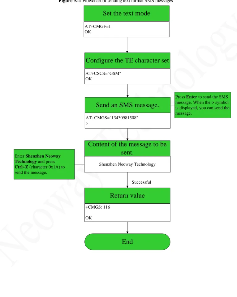
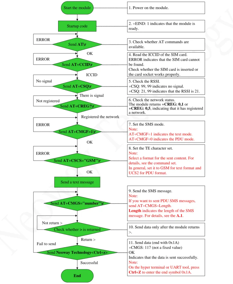
A.2 Flowchart of Sending Text SMS Messages (Through UART) ... 140
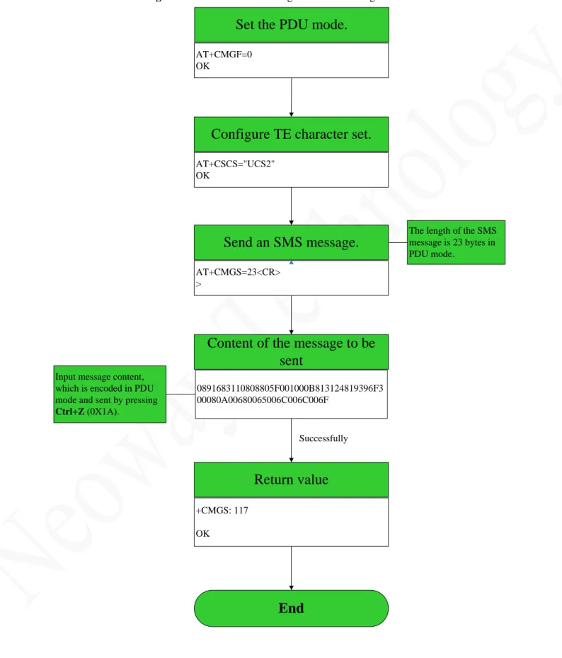
A.3 Flowchart of Sending PDU SMS Messages (Through UART) ... 141
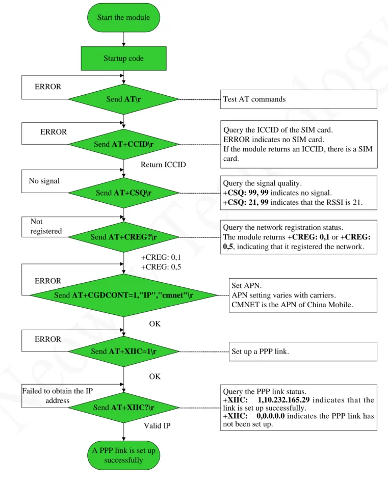
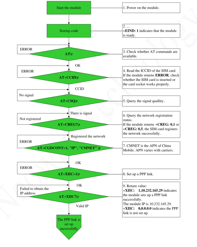
A.4 Flowchart of AT Commands to Establish TCP Link... 142
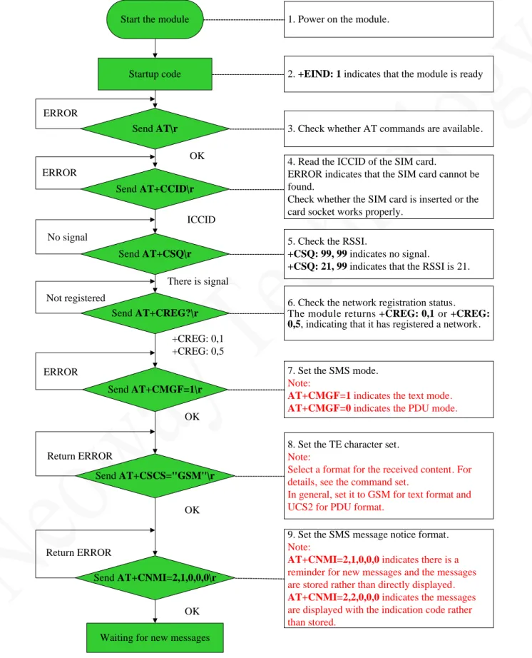
A.5 Flowchart of Receiving SMS Messages ... 144
A.6 Flowchart of Sending SMS Messages ... 146
A.7 Common AT Commands for SMS TX/RX ... 147
Copyright © Neoway Technology Co., Ltd 1
Boot LOG Instruction
After the module is booted, the UART sends the following boot LOG: MODEM:STARTUP
+PBREADY
LOG LOG Description
1 MODEM:STARTUP Indicates that the module starts up successfully and can receive AT commands.
5 +PBREADY SMS and phonebook are available.
Remarks Users can determine whether the module starts up successfully or not by detecting " MODEM:STARTUP ".
Copyright © Neoway Technology Co., Ltd 2
1 General Commands
1.1 Querying the Manufacturer: +CGMI
Description To query the manufacturer informationFormat AT+CGMI<CR> Parameter N/A Return Value <CR><LF>+CGMI:<manufacturer><CR><LF> <CR><LF>OK<CR><LF> Example AT+CGMI +CGMI:Neoway Corp Ltd OK Remarks N/A
1.2 Querying the Module Model: +CGMM
Description To query the module modelFormat AT+CGMM<CR> Parameter N/A Return Value <CR><LF>+CGMM:<model><CR><LF> <CR><LF>OK<CR><LF> Example AT+CGMM +CGMM:M660A OK Remarks N/A
1.3 Querying the Version: +CGMR
Description To query the software versionFormat AT+CGMR<CR> Parameter N/A Return Value <CR><LF>+CGMR:<version><CR><LF> <CR><LF>OK<CR><LF> Example AT+CGMR
Copyright © Neoway Technology Co., Ltd 3
+CGMR:M660A_1128_LQS13001_V001
OK
Remarks N/A
1.4 Querying IMEI: +CGSN
Description To query the International Mobile Equipment Identity (IMEI) of the module Format AT+CGSN<CR> Parameter N/A Return Value <CR><LF><IMEI><CR><LF> <CR><LF>OK<CR><LF> Example AT+CGSN 864894010024181 OK
The IMEI is a character string of 15 digits.
Remarks N/A
1.5 Querying the IMSI: +CIMI
Description To query the international mobile subscriber identification (IMSI) Format AT+CIMI<CR> AT+CIMI?<CR> Parameter N/A Return Value <CR><LF><IMSI><CR><LF> <CR><LF>OK<CR><LF> or <CR><LF>+CIMI: "IMSI"<CR><LF> <CR><LF>OK<CR><LF> or <CR><LF>ERROR<CR><LF> Or
<CR><LF>+CME ERROR: <err><CR><LF>
Example AT+CIMI
460022201575463
Query the IMSI.
Copyright © Neoway Technology Co., Ltd 4
OK AT+CIMI?
+CIMI: "460020188385503"
OK
Query the IMSI.
IMSI: 460020188385503
AT+CIMI ERROR
No SIM card is installed, so the module returns ERROR.
AT+CIMI? ERROR
No SIM card is installed, so the module returns ERROR.
AT+CIMI?
+CME ERROR: 10
After AT+CMEE=1 is set, the module returns +CME ERROR: 10 if no SIM card is installed.
Remarks IMSI is a character string of 15 digits and starts with 3-bit MCC and 2-bit MNC. It is used to authenticate the SIM card.
1.6 Obtaining the ICCID of the SIM Card: +CCID
Description To obtain the integrated circuit card identifier (ICCID) of the SIM card Format AT+CCID<CR> Parameter N/A Return Value <CR><LF>+CCID:<ICCID><CR><LF> <CR><LF>OK<CR><LF> Or <CR><LF>ERROR<CR><LF> Example AT+CCID +CCID: 89860002190810001367 OK Read command AT+CCID ERRORIf no SIM card is installed, ERRORis returned.
Copyright © Neoway Technology Co., Ltd 5
2 Mobile Device Control and Status Report
2.1 Querying the Module Status: +CPAS
Description To query the work status of the module Format AT+CPAS<CR>
AT+CPAS?<CR>
Parameter <pas>:
0: ready. The module is ready and is able to execute AT commands. 1: unavailable. The command is not allowed by the module terminal (MT). 2: unknown. The status is unknown.
3: ringing. There is an incoming call and the module is ringing. The module can execute AT commands.
4: call in progress. A call is going on and the module can execute AT commands. 5: asleep. The module is in the sleep mode and not prepared.
Return Value <CR><LF>+CPAS:<pas><CR><LF> <CR><LF>OK<CR><LF> or <CR><LF>+CME ERROR:<err><CR><LF> Example AT+CPAS +CPAS: 0 OK
Query the work status of the module. The module is ready to execute AT commands.
AT+CPAS=? +CPAS: (0-5)
OK
To query the value range of the module work status
AT+CPAS
+CME ERROR:<err>
Query the current status of the module.
+CME ERROR:<err> is returned. This value is returned only after you set
AT+CMEE=1.
Remarks N/A
2.2 Querying the Network Registration Status: +CREG
Description To query the network registration status of the moduleFormat AT+CREG=[<n>]<CR> AT+CREG?<CR> AT+CREG=?<CR>
Copyright © Neoway Technology Co., Ltd 6
Parameter <n>: Specified whether to enable network registration unsolicited result codes. 0: Disable network registration unsolicited result codes (default setting). 1: Enable network registration unsolicited result codes +CREG: <stat>.
2: Enable network registration and location information (Cell ID, Local ID) unsolicited result code +CREG: <stat>[,[<lac>],[<ci>],[<AcT>]]
<stat>: network status
0: Not registered, the module is not currently searching an operator to register to 1: Registered the home network
2: Not registered, but the module is currently trying to attach or searching an operator to register to
3: Registration denied 4. Unknown code 5: Registered, roaming
<lac>: Two byte location area code in hexadecimal format, string type
<ci>: four byte GERAN/UTRAN cell ID in hexadecimal format, string type
<Act>: The access technology of the serving cell, integer type 0: GSM 2: UTRAN 3: GSM w/EGPRS Return Value <CR><LF>+CREG:<n>,<stat>[,<lac>,<ci>[,<Act>]]<CR><LF> <CR><LF>OK<CR><LF> Or <CR><LF>ERROR<CR><LF> or <CR><LF>+CME ERROR:<err><CR><LF> Example AT+CREG=1 OK
Enable network registration unsolicited codes.
AT+CREG? +CREG: 0,1
OK
Query the network registration status of the module.
AT+CREG=? +CREG: (0-2)
OK
Query the value range of the network registration status parameter.
AT+CMEE=1 OK
AT+CREG=5 ERROR
Set AT+CMEE=1 (or run
AT+CMEE without parameter) after a SIM card is installed. Send the
AT+CREG=5 command and
ERROR is returned.
AT+CMEE=1 Set AT+CMEE=1 after a SIM card
Copyright © Neoway Technology Co., Ltd 7
OK
AT+CREG=5 +CME ERROR: 100
command and ERROR is returned.
Remarks N/A
2.3 GPRS Network Registration: +CGREG
Description To control the presentation of an unsolicited result code of the module's GPRS network registration status
Format
AT+CGREG=[<n>]<CR> AT+CGREG?<CR> AT+CGREG=?<CR>
Parameters
<n>: Specifies whether to enable network registration unsolicited result code 0: Disable network registration unsolicited result code (default)
1: Enable network registration unsolicited result code +CGREG: <stat>
2: Enable network registration and location information unsolicited result code +CGREG: <stat>[,<lac>,<ci>[,<Act>]]
<stat>: GPRS registration status, integer type
0: Not registered, the module is not currently searching an operator to register to 1: Registered the home network
2: Not registered, but the module is currently trying to attach or searching an operator to register to
3: Registration denied 4. Unknown code 5: Registered, roaming
<lac>: Two byte location area code in hexadecimal format, string type
<ci>: four byte GERAN/UTRAN cell ID in hexadecimal format, string type
<Act>: The access technology of the serving cell, integer type 0: GSM 2: UTRAN 3: GSM w/EGPRS Return Value <CR><LF>+CGREG: <n>,<stat>[,<lac>,<ci>[,<Act>]]<CR><LF> <CR><LF>OK<CR><LF> or <CR><LF>OK<CR><LF> or <CR><LF>ERROR<CR><LF>
Copyright © Neoway Technology Co., Ltd 8 Example AT+CGREG=1 OK AT+CGATT=0 OK +CGREG: 4
Enable network registration result code.
Set GPRS detaching.
The module returns unsolicited result code. AT+CGREG=2 OK AT+CGATT=1 +CGREG: 2, "286F", "00000FCA", 3 OK +CGREG: 1, "286F", "00000FCA", 3
Enable network registration and location information result code.
Set GPRS attachment.
The module returns unsolicited result code.
The module returns OK after attaching GPRS successfully.
The module returns unsolicited result code.
AT+CGREG? +CGREG: 0,1
OK
Query the current GPRS network
registration status. The network registration unsolicited result code is disabled.
AT+CGREG? +CGREG: 1,1
OK
Query the current GPRS network
registration status. The network registration unsolicited result code is enabled.
AT+CGREG?
+CGREG: 2,1,"286F","00000FCA",3
OK
Query the current GPRS network
registration status. The network registration and location information unsolicited result code is enabled.
AT+CGREG=3 ERROR
The set value exceeds the parameter range and the module returns ERROR.
AT+CGREG=? +CGREG: (0-2)
OK
Query the available parameter range.
Remarks N/A
2.4 Setting Module Functions: +CFUN
Description To select the functions of the module by setting <fun>Copyright © Neoway Technology Co., Ltd 9
Format AT+CFUN=[<fun>[,<rst>]]<CR> AT+CFUN?<CR>
AT+CFUN=?<CR>
Parameter <fun>:
1: All functions (Default)
4: Turn off the RF transmit and receive circuit of the module (flight mode). 0: Turn off the radio and SIM power (minimum functions).
<rst>:
0: Do not reset the MT before setting it to <fun> power level. 1: Reset the MT before setting it to <fun> power level
Return Value
<CR><LF>+CFUN:(list of supported <fun>s), (list of supported <rst>s)<CR><LF> <CR><LF>OK<CR><LF> or <CR><LF>+CME ERROR:<err><CR><LF> Or <CR><LF>ERROR<CR><LF> Example AT+CFUN=1 OK
Set the module to work with all functions.
AT+CFUN=0 OK AT+CFUN=1 OK +EUSIM: 0 +STKPCI: 0,"D081D881030125008202818285118052 A8611F57305E2600530049004D53618F0 E0180621176848EAB4EFD8BA48BC18F 0A02808D857EA753F77C3F8F0E0380621 176847CBE54C163A883508F10048065E0 7EBF97F34E504FF14E5090E88F0E05800 031003300394E9280547F518F0A068079F B52A87CBE54C18F0E078079FB52A84F1 860E04E13533A8F0E088079FB52A87535 5B50554652A18F12098062117684005300 49004D84254E1A53858F080A808D224FE 1901A8F0A0B8062117684573076D88F0A 41805E9475287BA174068F0A42804E0B8 F7D8BBE7F6E"
Turn of the SIM power and turn on all functions again. The module will return the SIM care information.
AT+CFUN? +CFUN: 1
Query the current functions. All functions are turned on.
Copyright © Neoway Technology Co., Ltd 10
OK
AT+CFUN=? +CFUN: (0,1,4),(0,1)
OK
Query the range of the parameter value.
AT+CMEE=1 OK
AT+CFUN ERROR
Set AT+CMEE=1 after a SIM card is installed. Send the AT+CFUN command and ERROR is returned.
AT+CMEE=1 OK
AT+CFUN
+CME ERROR: 100
No SIM card is installed and set
AT+CMEE=1. Send the AT+CFUN
command and ERROR is returned.
Remarks The setting of this command is not saved after the module is powered off.
2.5 Enabling or Disabling the Sleep Mode: +ENPWRSAVE
Description To enable or disable the sleep modeFormat AT+ENPWRSAVE=<n><CR> AT+ENPWRSAVE?<CR>
Parameter <n>:
0: Disable the sleep mode. (Default)
1: Enable the sleep mode (The module enters the sleep mode when the DTR signal is at low level and exits from the sleep mode at high level).
2: Enable the sleep mode (The module enters the sleep mode when the DTR signal is at high level and exits from the sleep mode at low level).
Return
Value See the Example.
Example AT+ENPWRSAVE=1
OK
Enable the sleep mode of the module.
AT+ENPWRSAVE? +ENPWRSAVE: 1
OK
Query the enabling status of the sleep mode of the module.
Remarks The setting of the parameter <n> will not be saved after the module is powered off. The DTR signal of the module is at low level by default.
After the sleep mode is enabled and the DTR signal is at low (or high) level, the module
Copyright © Neoway Technology Co., Ltd 11
The DTR signal drive can wake the module up at high (low) level.
2.6 Clock: +CCLK
Description To set and query the real-time clock Format AT+CCLK=<time><CR>
AT+CCLK?<CR>
Parameter < time >: Character string in format of "YY/MM/DD,hh:mm:ss+TZ".
TZ: Two digits, indicating the time lag between the local time and the GMT time. This information is optional because it can be displayed only when the network supports it. A pair of quotation marks ("") is a must.
Return
Value See the Example
.
Example AT+CCLK="11/10/14,09:30:16" OK
Set the real-time clock of the module.
AT+CCLK="11/10/14,09:30:" ERROR
Command format is incorrect.
AT+CCLK?
+CCLK: "11/10/14,09:32:04"
OK
Query the setting of the real-time clock.
Remarks The settings will not be saved after the module is powered off.
2.7 Setting the Baudrate of the Module: +IPR
Description To set the baudrate of the moduleFormat AT+IPR=<baud rate><CR> AT+IPR?<CR>
AT+IPR=?<CR>
Parameter <baud rate>: The value can be: 300, 600, 1200, 2400, 4800, 9600, 14400, 19200, 38400, 57600, 115200, 230400, 460800, and 921600.
Return Value
See the Example.
Example AT+IPR=115200
OK
Set the baudrate of the module to 115200.
AT+IPR=100 ERROR
Set the baudrate to 100 that is not a valid value. ERROR is returned.
Copyright © Neoway Technology Co., Ltd 12
AT+IPR? +IPR: 115200
OK
Query the current baudrate of the module. AT+IPR=? +IPR: 300, 600, 1200, 2400, 4800, 9600, 14400, 19200, 38400, 57600, 115200, 230400, 460800, 921600 OK
Query the valid baudrate range of the module.
Remarks The default baudrate is 115200.
The settingsby this command will be saved after the module is powered off.
2.8 Entering the PIN Codes: +CPIN
Description To query the PIN status and enter the PIN codes Format AT+CPIN=<pin>[,<newpin>]<CR> AT+CPIN=<PUK>,<PIN><CR> AT+CPIN?<CR>
Parameter <pin>, <newpin>:string type with a pair of quotation marks ("") <PUK>: PUK code of the SIM card
<PIN>: PIN code of the SIM card Return Value <CR><LF>+CPIN:<code><CR><LF> <CR><LF>OK<CR><LF> <code>: READY: No password SIM PIN: Enter PIN code. SIM PUK: Enter PUK code. SIM PIN2: Enter PIN2 code. SIM PUK2: Enter PUK2 code.
Example AT+CPIN?
+CPIN:READY
OK
Query the PIN code status of the module.
AT+CPIN? ERROR
Copyright © Neoway Technology Co., Ltd 13
AT+CPIN? +CPIN: SIM PIN
OK
PIN code is required.
AT+CLCK="SC",1,"1234" OK
MODEM:STARTUP AT+CPIN?
+CPIN: SIM PIN
OK AT+CPIN="1234" OK +PBREADY +EIND: 2 +EIND: 1
Restart the module after locking the SIM card. Enter the PIN code to unlock the SIM card, and the modules will return the following code:
+PBREADY, +EIND: 2, +EIND: 1
AT+CPIN="1245" ERROR
PIN code is incorrect.
AT+CPIN="1234" OK
The input PIN code is correct.
AT+CPIN? +CPIN: SIM PUK
OK
PUK code is required.
AT+CPIN="78357381","0000" OK
"78357381": Correct PUK code "0000": New PIN code
Remarks To enter PIN code, you must lock the current SIM card (running
AT+CLCK="SC",1,"1234") and then restart the module.
After correct PIN code is input, the module will return code indicating that the
initialization is completed. AT+CPIN="1234" OK
Copyright © Neoway Technology Co., Ltd 14 0,"D081B6810301250082028182850B80795E5DDE884C592957308F0A01808F7B677 E95EE50198F0A028077ED4FE17FA453D18F0A0380670065B063A883508F0A04804 E1A52A17CBE90098F10058065E07EBF97F34E504FF14E5090E88F0E068000310033 00394E9280547F518F0807808D224FE1901A8F0E088079FB52A84F1860E04E13533 A8F0E098079FB52A875355B50554652A18F120A806211768400530049004D84254E1 A53858F0E0B8000530049004D53614FE1606F" +EIND: 2 +EIND: 1
If you enter wrong PIN code for three times, you must enter PUK to unlock.
2.9 Enabling PIN and Querying MT and Network Device:
+CLCK
Description To lock, unlock or interrogate an ME or a network facility Format AT+CLCK=<fac>,<mode>[,<passwd>[,<class>]]<CR>
AT+CLCK=?<CR>
Parameter <fac>: A pair of quotation marks is a must for the value. "OI": Outgoing international calls
"AI": All incoming calls
"IR": Incoming calls when roaming outside the home country "SC": SIM card
"AO": All outgoing calls
"OX": All outgoing international calls except to the home country "AB": All barring services
"AG": All outgoing barring services "AC": All incoming barring services "FD": SIM fixed dialing memory feature "PS": PH-SIM (lock Phone to SIM card) "PN": Network authentication
"PU": Network subsystem authentication PP: Service provider authentication "PC": Corporate authentication <mode>:
0: Unlock 1: Lock
2: Query the status <status>:
0: not active 1: active
Copyright © Neoway Technology Co., Ltd 15 <classx>: 1: Voice service 2: Data service 4: Fax service 8: SMS
16: Synchronous data service 32: Asynchronous data service 64: Dedicated packet access 128: Dedicated PAD access Return
Value
When <mode>=2 and command successful:
<CR><LF>+CLCK:<status> [, <class1> [<CR><LF>+CLCK:<status>, <class2> [...]]<CR><LF> Example AT+CLCK="SC",2 +CLCK: 0 OK AT+CLCK=? +CLCK:("PF","SC","AO","OI","OX","AI", "IR", "AB","AG","AC","FD","PN","PU","PP", "PC") OK
Query the network information related to the module.
AT+CLCK="SC",1,"1234" OK
Lock the current SIM card. "1234" is the PIN code of current SIM card.
AT+CLCK="SC",0,"1234" OK
Unlock the current SIM card. "1234" is the PIN code of current SIM card.
Remarks The settings of this command take effect after the module is restarted.
2.10 Modifying the Password of the PIN: +CPWD
Description To modify the password of the lock function of the moduleFormat AT+CPWD=<fac>,<oldpwd>,<newpwd><CR> AT+CPWD=?<CR>
Parameter <fac>: A pair of quotation marks is a must for the value. "P2":SIM PIN2
"OI": Outgoing international calls "AI": All incoming calls
Copyright © Neoway Technology Co., Ltd 16
"SC": SIM card
"AO": All outgoing calls
"OX": All outgoing international calls except to the home country "AB": All calling services
"AG": All outgoing call services "AC": All incoming call services "FD": Fixed dialing of the SIM card "PN": Network authentication
"PU": Network subsystem authentication "PP": Service provider authentication "PC": Corporate authentication
<oldpwd>: Old password or code, string type. A pair of quotation marks is a must for the value.
<newpwd>: New password or code, string type. A pair of quotation marks is a must for the value.
Return Value
<CR><LF>+CPWD:list of supported (<fac>,<pwdlength>)s<CR><LF> <CR><LF>+CME ERROR:<err><CR><LF> Example AT+CPWD=? +CPWD:("SC",8),("P2",8),("AO",4),("OI", 4), ("OX",4),("AI",4),("IR",4),("AB",4), ("AG",4),("AC",4) OK
Query the service range of the PIN password allowed by the module.
AT+CPWD="SC","1234","0000" OK
Modify the PIN code of the current SIM card. "1234" is the old PIN code and "0000" is the new PIN code.
AT+CPWD=SC,1234,0000 ERROR
The command format is incorrect. A pair of quotation marks ("") is required for each parameter.
Remarks To modify the PIN code, you must lock the SIM card (running
AT+CLCK="SC",1,"1234").
2.11 Extended Error Report: +CEER
Description To return text information <report> of one line or multiple lines (determined by the ME manufacturers) Format AT+CEER<CR> Parameter N/A Return Value <CR><LF>+CEER:<cause>, <report><CR><LF> <CR><LF>OK<CR><LF>
Copyright © Neoway Technology Co., Ltd 17
<cause>:cause value listed in GSM 04.08 annex H.
<report>: The ME manufacturer provides the extended report about the following error causes:
Failure of the latest call (initiate or answer) or modification during the call Release of the latest call
The latest GPRS attach failure or PDP context activation The latest GPRS detach or PDP context deactivation
Example AT+CEER
+CEER:0, NONE
OK
Execute the ERROR report command.
AT+CEER
+CEER: 16, CM_NORMAL_CALL_CLR
OK
The module initializes a call and ends the call manually after the recipient rings.
AT+CEER
+CEER: 31, CM_NORMAL_UNSPECIFIED
OK
The module initializes a call and ends the call automatically since the recipient does not answer the call.
AT+CEER
+CEER: 17, CM_USER_BUSY
OK
The module initializes a call and the recipient refuses the call manually.
Remarks N/A
2.12 Setting Error Information: +CMEE
Description To enable or disable the +CME ERROR:<err> result code Format AT+CMEE=[<n>]<CR>
AT+CMEE?<CR> AT+CMEE=?<CR>
Parameter <n>:
0: Disable the +CME ERROR:<err> result code and display ERROR. (default) 1: Enable the +CME ERROR:<err> result code and use the numeric <err> value. 2: Enable the +CME ERROR:<err> result code and use verbose <err> values. Return
Value See the Example
.
Example AT+CMEE=1
OK
Copyright © Neoway Technology Co., Ltd 18
AT+CMEE? +CMEE: 1
OK
Query the status of the current result code.
AT+CMEE=? +CMEE: (0-2)
OK
Query the status range of error code.
Remarks The setting of the parameter in this command is not saved after the modules is powered
off.
It is recommended that you set AT+CMEE=2 during commissioning.
2.13 Setting the Signal Indicator Status: +SIGNAL
Description To set the different blinking status of the signal indicatorFormat AT+SIGNAL=<value><CR> AT+SIGNAL?<CR>
AT+SIGNAL=?<CR>
Parameter <value>:Integers, ranging from 0 to 5
0: Blink once every second in normal situation. Being off or on if any abnormality occurs. 1: Blink once every second after the module is connected to the GPRS data service. Being off in any other situations.
2: Flash and blink. Flash every 250 ms for the GPRS data service and blink every second in other normal situations.
3: Be on after the GPRS data service is connected and blink every second in other situations.
4: Being on after the GPRS data service is connected and being off in other situations. 5: Being off if the SIM card cannot be detected after the module is powered on, blinking every second if the SIM card is detected, and being on after the GPRS data service is connected.
6: Four indicator states:
If no SIM card is installed or the SIM card does not register network, the indicator blinks
every one second and is on for 0.1 second.
If the SIM card registered network, the indicator blinks every three second and is on for
0.1 second.
If the GPRS data service is enabled, the indicator blinks every 125 ms and is on for 0.1
second.
The indicator is always on during a call.
Return Value
See the Example.
Example AT+SIGNAL?
+SIGNAL: 2
Copyright © Neoway Technology Co., Ltd 19
OK
AT+SIGNAL=3 OK
Set current signal indicator status to 3.
AT+SIGNAL=7 ERROR
The parameter is set to an incorrect value.
AT+SIGNAL=? +SIGNAL: (0-5)
OK
The available value of the signal indicator status ranges from 0 to 5.
Remarks The default status setting is 2.
The settingsby this command will be saved after the module is powered off.
2.14 Enabling the Hardware or Software Flow Control Function:
+IFC
Description To enable the hardware or software flow control function Format AT+IFC=<n1>,<n2><CR>
AT+IFC=?<CR> AT+IFC?<CR>
Parameter <n1>:value ranges from 0 to 2. <n2>:value ranges from 0 to 2. Return
Value See the Example.
Example AT+IFC=1, 1 Enable the software flow control
function.
AT+IFC=2, 2 Enable the hardware flow control function.
AT+IFC=0, 0 Disable the flow control function.
AT+IFC=0,1 ERROR
The parameter combination is not allowed. Only (0,0), (1,1), and (2,2) are allowed.
AT+IFC=? +IFC: (0-2),(0-2)
OK
Query the value ranges of flow control function.
Copyright © Neoway Technology Co., Ltd 20
AT+IFC? +IFC: 0, 0
OK
Query the current status of the flow control function.
Remarks You must configure the U1RTS and U1CTS pins before enabling the hardware flow
control. For details, see the AT+FCHW command.
This command supports only the (n1, n2) parameter combination: (0,0);(1,1);(2,2).
OK will be returned after the command is executed successfully.ERROR will be returned for other parameter combinations.
2.15 Enabling & Disabling the Terminal Display: ATE1/ATE0
Description To enable or disable the terminal display function of the AT commandsFormat ATE1<CR> ATE0<CR>
Parameter N/A Return
Value See the Example
.
Example ATE1
OK AT OK
Enable the terminal display function of the AT commands.
ATE0 OK OK
Disable the terminal display function of the AT commands.
Remarks The settings by this command will not saved after the module is powered off. The terminal display function is enabled by default.
If you enter the command mode after dialing up to connect with the network, terminal
display is disabled automatically.
ATE is equal to ATE1.
2.16 Setting the Code Result Suppression Mode: ATQ
Description To set the mode whether to suppress the code resultFormat ATQ[<value>]<CR> Parameter <value>: 0, 1
0: Output the code result (default) 1: Suppress the code result Return See the Example.
Copyright © Neoway Technology Co., Ltd 21
Value
Example ATQ1AT+CSQ
+CSQ: 31, 99
Set to code result suppress mode. (The module does not return OK after this command is executed successfully.) After the mode is set, the return value for the AT+CSO command does not contain the code result OK.
ATQ0 OK AT OK
Set to the code result output mode. After the mode is set, the return value for the AT command contains the code result OK.
Remarks After you set to the code result suppression mode, the command will not output OK or
ERROR.
The setting by this command cannot be saved after the module is powered off. The
setting is valid only for the GSM commands and invalid for customized commands.
ATQ is equal to ATQ1.
2.17 Setting the Response Format of the Device: ATV
Description To set the response format of the deviceFormat ATV[<value>]<CR> Parameter <value>: 0, 1
0: Set the response format to output with only some header, footer, and digit text. 1: Set the response format to output with all headers, footers, and detailed response text (default).
Return
Value See the Example
. Example ATV1 OK AT+CSQ +CSQ: 31, 99 OK
Set the response format to output with all headers, footers, and detailed response text.
After the format is set successfully, the module returns the following value after you execute AT+CSQ: +CSQ: 31, 99
OK ATV00
AT+CSQ+CSQ: 31, 99 0
Set the response format to output with only some header, footer, and digit text. The module returns 0 after the format is set successfully.
After the format is set successfully, the module returns the following value after you execute AT+CSQ:
Copyright © Neoway Technology Co., Ltd 22
+CSQ: 31, 99 0
Remarks ATV is equal to ATV1.
After you execute ATV0, the return value for a command in correct format is 0 (default
setting is OK); 4 for command in incorrect format (default setting is ERROR).
The setting by this command will not be saved after the module is powered off. The
setting is valid only for the GSM commands and invalid for customized commands.
2.18 Resetting to the Default Setting: ATZ
Description To reset the module to the default settingFormat ATZ[<value>]<CR> Parameter <value>: 0, 1
You can use the command to reset the module to the default setting both with valid parameter values and without this parameter.
Return Value
See the Example.
Example ATZ1
OK
Reset the module to the default setting.
ATZ0 OK
Reset the module to the default setting.
Remarks If you have set the module to the code result suppression mode (ATQ1), you can reset it to the default settings by executing this command.
2.19 Saving Parameter Settings: AT&W
Description To save parameter settingsFormat AT&W<CR>
Parameter NULL
Return Value
See the Example
Example AT+REMOTEAT? +REMOTEAT: 0 OK AT+REMOTEAT=1 OK AT&W OK
Query the current parameter value. The value is 0.
Set commands that support parameter saving.
Copyright © Neoway Technology Co., Ltd 23
AT+REMOTEAT? +REMOTEAT: 1
OK
module.
Query the current parameter value. The value is 1.
AT&W0 OK
Save parameter settings. This command has the same function as AT&W. Remarks The following commands support parameter saving:
ATE, +CMEE, ATV, ATQ, +CSCS, +COPS, +CCWA, +CREG, +CLIP,
+ENPWRSAVE, +DATAFORMAT, +TRANMODE, +RSMODE, +EXTRARING, +FCHW, +TTSFMT, +RINGOUT, +REMOTEAT, etc.
AT&W0 is equal to AT&W. To restore to the default settings, you can execute AT&F
or ATZ.
2.20 Resetting the Module to Factory Settings: AT&F
Description To reset the module to the factory settingsFormat AT&F[<value>]<CR> Parameter <value>
0: Reset the module to factory settings. Return
Value
See the Example.
Example AT&F0 OK
Reset the module to factory settings.
AT&F OK
Reset the module to factory settings.
Remarks If you have set the module to the code result suppression mode (ATQ1), you can reset it
to factory settings by executing this command.
This command is similar to the ATZ command in function.
2.21 Reading ADC Value: +READADC
Description To read the value from pins corresponding to the three ADC channels Format AT+READADC=<channel><CR>
Parameter <channel>: Integer, ranging from 0 to 2, which indicates three ADC channels Return
Value
See the Example
Example AT+READADC=0
+READADC:0,53
Read the value from the pin corresponding to ADC 0.
Copyright © Neoway Technology Co., Ltd 24
OK
AT+READADC=2 +READADC:2,3244
OK
Read the value from the pin corresponding to ADC 2.
AT+READADC=3 ERROR
The parameter value is invalid.
Remarks Refer to the pin description in hardware user guide.
2.22 Jamming Detect: +JAMMINGDETECT
Description To detect GSM jammingFormat AT+JAMMINGDETECT=<mod1>,<mod2>[,<mod3>]<CR> AT+JAMMINGDETECT?<CR>
Parameter <mod1>: Detection mode, ranging 1 to 2 1: Detection of all channels
2: Detection of part channels (based on the value of <mod3>) <mod2>: Strength of jamming to be detected, ranging from 1 to 3 1: High
2: Medium 3: Low
If you set the strength of jamming to be detected to low, it easier to detect weak jamming. <mod3>: Channel selection, ranging from 1 to 2
1: 900/1800 channel 2: 850/1900 channel
(This parameter is valid only when <mod1> is 2. Return
Value
See the Example
Example AT+JAMMINGDETECT=1,1
OK
AT+JAMMINGDETECT? OK
Set detection parameters and enable jamming detection.
Query the detection. No jamming is detected. AT+JAMMINGDETECT=1,1
OK
AT+JAMMINGDETECT? OK
+JAMMING DETECKED Detected jamming.
Copyright © Neoway Technology Co., Ltd 25
sequence.
2.23 Activating Multiplexing Mode: +CMUX
Description To activate multiplexing modeFormat
AT+CMUX=<mode>[,<subset>[,<port_speed>[,<N1>[,<T1>[,<N2>[,<T2>[,<T3>[,<k>]
]]]]]]]<CR>
AT+CMUX=?<CR>
Parameters
<mode>: The mode of MUX that is enabled, integer type 0: Basic option (default value)
1: Advanced option (not supported currently)
<subnet>: Subset of frame format, integer type 0: UIH frames used only (default value)
1: UI frames used only (not supported currently)
<port_speed>: UART port rate, integer type 1: 9600bit/s
2: 19200bit/s 3: 38400bit/s 4: 57600bit/s
5: 115200bit/s (default value) 6: 230400bit/s
<N1>: Maximum frame size. Integer type, ranging from 1 to 32768. The range of 1 to 1509 is supported currently. The default value is 31. If you select Advanced option for mode, the default value is 64.
<T1>: Acknowledgement timer in unite of ten milliseconds, integer type, ranging from 1 to 255, where 10 is default (100 ms).
<N2>: Maximum number of re-transmission, integer type, ranging from 1 to 100, where 3 is the default value. The range of 0 to 5 is supported currently.
<T2>: response timer for the multiplexer control channel in units of ten milliseconds, integer type, ranging from 2 to 255, where 30 is default (300 ms)
<T1>: Wake up response timer in seconds, integer type, ranging from 1 to 255, where 10 is default (10s)
This parameter is not supported and the module returns 0 for it.
<k>: window size, for Advanced option with Error-Recovery Mode, integer type, ranging from 1 to 7, where 2 is default
This parameter is not supported and the module returns 0 for it.
Return Value <CR><LF>OK<CR><LF>
Example
AT+CMUX=0 OK
Basic option. Other parameters are left out.
AT+CMUX=2 ERROR
The set value exceeds the parameter range and the module returns ERROR.
Copyright © Neoway Technology Co., Ltd 26
AT+CMUX=0,0,,512,254,5,255 OK
Mode: Basic option Subset: UIH
Transmission rate: default value Max. frame size: 255
Acknowledgement timer: 2540 ms Max. number of retransmission: 5 Response timer: 2550 ms
AT+CMUX=1,0,,512,254,5,255 ERROR
Advanced option, which is not supported The module returns ERROR.
AT+CMUX=? +CMUX:
(0),(0),(1-6),(16-1510),(1-255),(0-100),(2-25 5),(1-255),(1-7)
OK
Query the available range of parameters.
AT+CMUX? ERROR
The command format is incorrect. The module returns ERROR.
Remarks
In accordance with the multiplexing protocol, two or more virtual channels are set up on
one physical port.
In general, three virtual channels are set up, among which one is used for dialing up to access the Internet, and two are used for AT command sending and receiving.
<T2> must be longer than <T1>.
It is recommended that you use AT+CMUX=0 to enable the multiplexing protocol control
Copyright © Neoway Technology Co., Ltd 27
3 Network Service Commands
3.1 Querying Signal Quality: +CSQ
Description To check the receiving signal strength indication (RSSI) and the bit error rate (BER) of the channel Format AT+CSQ<CR> AT+CSQ=?<CR> Parameter N/A Return Value <CR><LF> +CSQ:< signal >, <ber><CR><LF> <CR><LF> OK <CR><LF> < signal>
The following table shows the relationship between the signal and the RSSI. signal rssi 0 <4 or 99 <-107 dBm or unknown 1 <10 <-93dBm 2 <16 <-71 dBm 3 <22 <-69dBm 4 <28 <-57dBm 5 >=28 >=-57 dBm <ber>
0...7 Refer to the value of RXQUAL in the table of GSM 05.08 8.2.4.
99 Not known or not detectable
Example AT+CSQ
+CSQ: 1, 99
OK
Query the current signal strength of the module.
AT+CSQ=?
+CSQ: (0-31,99),(0-7,99)
OK
Query the range of the module signal strength.
Copyright © Neoway Technology Co., Ltd 28
3.2 Selecting and Registering a GSM Network: +COPS
Description To select and register a GSM networkFormat AT+COPS=[<mode>[,<format>[,<oper>>[,<AcT>]]]]<CR> AT+COPS?<CR>
AT+COPS=?<CR>
Parameter <mode>:
To set automatic network selection or manual selection: 0: Automatic selection (ignore the parameter <per>) 1: Manual selection
2: Deregister from the network 3: Set <format>only
4: Manual/automatic selection (if the manual selection fails, automatic mode starts) <format>:
0: Long alphanumeric <oper> (default value) 1: Short format alphanumeric <oper> 2: Numeric <oper>
<oper>:
It is given in <format>. This field may be in 16-character long alphanumeric format, 8-characters short alphanumeric format, or 5-character numeric format (MCC/MNC). <AcT>: Indicates the radio access technology and its value can be 0, 1, and 2. 0: GSM 1: GSM compact 2: UTRAN Return Value <stat>: 0: Unknown network 1: Available network 2: Current network 3: Forbidden network Example AT+COPS=0,0 OK
Automatic network selection is enabled. Long alphanumeric mode. AT+COPS=0,2
OK
Set to digital mode
AT+COPS?
+COPS:0,0,"China Mobile"
OK
Copyright © Neoway Technology Co., Ltd 29
AT+COPS?
+COPS: 0,2,"46000"
OK
If it is set to digital mode, get the number 46000 AT+COPS? +COPS:0,0,"China Unicom" OK China Unicom AT+COPS? +COPS: 0,2,"46001" OK
If it is set to digital mode, then get the number 46001. AT+COPS=? +COPS: (2,"ChinaUnicom","CU-GSM","46001",0), (3,"China Mobile","CMCC","46000",0),, (0-3),(0-2) OK
Query the range of network selection.
AT+COPS=2 OK
Deregister the network.
Remarks When you try to query the current network selection parameters, <AcT>is displayed only
if the device supports UMTS.
<AcT> indicates the access technology of the manual attach procedure if you choose
GSM/UMTS dual mode and select network manually.
Ignore the parameter <AcT> if you set automatic network selection.
3.3 Setting Band: +XBANDSEL
Description To set bandFormat AT+XBANDSEL=<band>[,<n>]<CR> AT+XBANDSEL?<CR>
AT+XBANDSEL=?<CR>
Parameter <band>: Band selection 850: 850M
900: 900M 1800: 1800M 1900: 1900M
Copyright © Neoway Technology Co., Ltd 30
0: not support 1: support
When <n> is omitted, only the current <band> is supported. Return
Value
See the Example
Example AT+XBANDSEL=900
OK
Supported band is set to 900M forcibly. 850M, 1800M, and 1900M are not supported.
AT+XBANDSEL? +XBANDSEL:850
OK
Query the current band supported. Support 850M band. AT+XBANDSEL=900,1 OK AT+XBANDSEL=1800,1 OK AT+XBANDSEL=850,0 OK AT+XBANDSEL=1900,0 OK
Set supported band to 900M forcibly.
Set supported band to 1800M forcibly.
Set 850M to band not supported forcibly.
Set 1900M to band not supported forcibly.
AT+XBANDSEL? +XBANDSEL:900,1800
OK
Query the current band that is set. Support 900M and 1800M bands.
AT+XBANDSEL?
+XBANDSEL:No Band Support
OK
Query the current band supported. No band is supported.
AT+XBANDSEL=?
+XBANDSEL:(850,900,1800,1900),(0,1)
OK
Query the value range of parameters.
Remarks
The settings by this command are saved after the module is powered off. By default all
those four bands are supported.
After this command is executed, the module will deregister the network. Then the
module need to register network again and you must set AT+COPS=0,0.It takes some time to set AT+COPS=0,0.
Copyright © Neoway Technology Co., Ltd 31
3.4 Locking BCCH Channel: $MYBCCH
Description To lock BCCH channelFormat AT$MYBCCH=<mode>[,<bcch1>,<bcch2>,<bcch3>]<CR> AT$MYBCCH?<CR>
AT$MYBCCH=?<CR>
Parameter <mode>: Integer. The settings of locked channel can be saved after the module is powered off only if you run AT$MYBCCH=1,XX. If the BCCH locked does not exist or its signal is weak, the module cannot register network.
0: Unlock
1: Lock the BCCH cell
2: List IDs of seven BCCH channels that have the strongest signals at current place. <bcch>: channel ID
<num>: the number of BCCH channels in the BA list (7 at most) <mcc>: Mobile country code
<mnc>: mobile network code
<lac>: Location ID, four-byte characters in hexadecimal format <cell-id>: Cell ID, hexadecimal
Return Value <CR><LF>OK<CR><LF> <CR><LF>$MYBCCH: +BA(num): <CR><LF><bcch1>,<mcc1>,<mnc1>,<lac1>,<cell-id1><CR><LF> <CR><LF><bcch2>,<mcc2>,<mnc2>,<lac2>,<cell-id2><CR><LF> <CR><LF><bcch3>,<mcc3>,<mnc3>,<lac3>,<cell-id3><CR><LF> ... <CR><LF>OK<CR><LF> <CR><LF>$MYBCCH: <bcch1>,<mcc1>,<mnc1>,<lac1>,<cell-id1><CR><LF> <CR><LF>OK<CR><LF> <CR><LF>$MYBCCH: UNLOCKED<CR><LF> <CR><LF>OK<CR><LF> <CR><LF>ERROR<CR><LF>
<CR><LF>$MYBCCH: <mode list>,<bcch1>,…<bcch3><CR><LF> <CR><LF>OK<CR><LF>
Example AT$MYBCCH=2
$MYBCCH: +BA(7):
120,460,01,2543,A85D
List IDs of seven BCCH channels that have the strongest signals at current place.
Copyright © Neoway Technology Co., Ltd 32 734,460,01,2543,AB12 712,460,01,2543,AFF4 715,460,01,2543,AB13 736,460,01,2543,AB14 115,460,01,2543,A85E 719,460,01,2543,B04F OK AT$MYBCCH=? $MYBCCH: (0,1,2),120,734,712 OK
Query the value range of parameters in this command. Channels 120, 734, and 712 can be locked. AT$MYBCCH=1,120 OK Lock channel 120. AT$MYBCCH=? $MYBCCH: (0,1,2),120 OK
Query the value range of parameters in this command. Channels 120 can be locked.
AT$MYBCCH?
$MYBCCH: 120,460,01,2543,A85D
OK
Query channels that are locked currently.
AT$MYBCCH=0 OK
Unlock
Remarks The settings by this command are saved after the module is powered off. This command does not support the BCCH channels of 1900M.
Copyright © Neoway Technology Co., Ltd 33
4 Calling Control Commands
4.1 Setting the Voice Volume: +CLVL
Description To set the level of the voice volume, which is valid before a call or during a call Format AT+CLVL=<level><CR>
AT+CLVL?<CR> AT+CLVL=?<CR>
Parameter <level>: Integers, ranging from 0 to 6. The default value is 3. Return
Value
See the Example.
Example AT+CLVL=4
OK
Set the level of the voice volume to 4.
AT+CLVL? +CLVL:4
OK
Query the level of voice volume of the module.
AT+CLVL=? +CLVL:0-6
OK
Query the valid voice volume level for the module.
Remarks The setting by this command is not saved after the module is powered off.
This command is used to set the volume level of the current voice ouput channe, which
can be reciever, earphone, speaker.
4.2 MIC Volume Control: +MICL
Description To set the level of the MIC volume in a call, which is valid during a call Format AT+MICL=<level><CR>
AT+MICL?<CR> AT+MICL=?<CR>
Parameter <level>: Integers, ranging from 0 to 6, the default value is 3. Return
Value
See the Example.
Example AT+MICL=3
OK
Set the level of the MIC volume to 3.
AT+MICL? +MICL:3
Query the current level of the MIC volume.
Copyright © Neoway Technology Co., Ltd 34
OK
AT+MICL=? +MICL:0-6
OK
Query the value range of MIC volume.
Remarks The settings by this command will not be saved after the module is powered off.
4.3 Mute Control: +CMUT
Description To set mute control of the voice calls. The setting is valid during a call Format AT+CMUT=<n><CR>
AT+CMUT?<CR> AT+CMUT=?<CR>
Parameter <n>:
0: Mute off (default value) 1: Mute on
Return Value
See the Example.
Example AT+CMUT=0
OK
Disable the mute mode.
AT+CMUT=1 ERROR
Enable mute control before a call.
AT+CMUT? +CMUT: 0
OK
Query whetherthe mute mode is enabled.
AT+CMUT=? +CMUT: (0,1)
OK
Query the value range of mute mode function.
Remarks This command is valid only during a call. ERROR will be returned in any other situations.
4.4 Dialing Command: ATD
Description To initialize a data, fax, or voice linkCopyright © Neoway Technology Co., Ltd 35
For a voice link, the dialing string consists of numbers and modifiers and must end with a semicolon.
Format ATD<dial string><CR> ATD><n><CR>
Parameter <dial string>:Phone number <n>:The location of phone number Return
Value
OK
SPEECH ON
ALERTING
If the call is hung up directly on the other side: SPEECH OFF
RELEASE
BUSY
The phone is picked up on the other side: CONNECT
If the call is hung up on the other side during the call SPEECH OFF
RELEASE
NO CARRIER
Example .0123456789+. Valid characters for origination
W The W modifier is ignored but is included for compatibility reasons only , The comma modifier is ignored but is included for compatibility reasons only ; Informs the Infrared Modem that the number is a voice number rather than a fax or data number
T The T modifier is ignored but is included only for compatibility purposes P The P modifier is handled (pulse DTMF dialing functionality)
28800 Connected with data bit rate of 28800 bits/s (HSCSD) 19200 Connected with data bit rate of 19200 bits/s (HSCSD) 14400 Connected with data bit rate of 14400 bits/s (HSCSD) 9600 Connected with data bit rate of 9600 bits/s
4800 Connected with data bit rate of 28800 bits/s 2400 Connected with data bit rate of 28800 bits/s
Copyright © Neoway Technology Co., Ltd 36 ATD15889758495; OK SPEECH ON ALERTING Make a call to 15889758495. ATD13510823499 ALERTING CONNECT CONNECT 9600 Fax to 13510823499. No semicolon (;). Data can be sent after the module returns
CONNECT<n>. ATD13510823499 ALERTING CONNECT RELEASE NO CARRIER RELEASE Fax to 13510823499. No semicolon (;). The fax link is released since data is sent before the module returns CONNECT<n>.
ATD>2; OK
SPEECH ON
ALERTING
Dial up the number listed as 2 in the phonebook.
Remarks There are two types of calls: voice call, data and fax call. Semicolon is required for voice calls and not required for data or fax calls.
4.5 Call Answering: ATA
Description To answer the call and establish a call connection
The return codes containing RING or +CRING indicate an incoming call. Format ATA<CR>
Copyright © Neoway Technology Co., Ltd 37 Parameter N/A Return Value <CR><LF>SPEECH ON<CR><LF> <CR><LF>OK<CR><LF>
If the call is hung up on the other side during the call, the command returns: <CR><LF>SPEECH OFF<CR><LF>
<CR><LF>RELEASE<CR><LF> <CR><LF>NO CARRIER<CR><LF>
Example 28800 Connected with data bit rate of 28800 bits/s (HSCSD) 19200 Connected with data bit rate of 19200 bits/s (HSCSD) 14400 Connected with data bit rate of 14400 bits/s (HSCSD) 9600 Connected with data bit rate of 9600 bits/s
4800 Connected with data bit rate of 28800 bits/s 2400 Connected with data bit rate of 28800 bits/s ATA
SPEECH ON
OK
Answer the call (voice).
ATA CONNECT
CONNECT 9600
Answer the call (fax).
Data can be sent after the module returns
CONNECT<n>.
Remarks N/A
4.6 Hanging Up Calls: ATH
Description To hang up all call links Format ATH<CR> Parameter N/A Return Value <CR><LF>SPEECH OFF<CR><LF> <CR><LF>RELEASE<CR><LF> <CR><LF>OK<CR><LF> Example ATH SPEECH OFF RELEASE OKCopyright © Neoway Technology Co., Ltd 38
ATH RELEASE
OK
Refuse the incoming call. Hang up the call.
Remarks N/A
4.7 Auto-Answer:ATS0
Description To control the auto-answer mode of the module Format ATS0=<value><CR>
ATS0?<CR>
Parameter <value>:Integers, ranging from 0 to 255 The default value is 000.
Return Value
See the Example.
Example ATS0=1
OK
Set the auto-answer for one ring.
ATS0? 001
OK
Query the status of the auto-answer function.
Remarks If ATS0=0, the auto-answer function is not enabled; otherwise, the module will automatically answer the call after ringing for certain times.
4.8 Caller ID: CLIP
Description To enable or disable caller ID Format AT+CLIP=<n><CR>
AT+CLIP?<CR> AT+CLIP=?<CR>
Parameter <n>:
0: disable caller ID
1: enable caller ID (default value) Return Value +CLIP:<n>,<m> <n>: 0: disable 1: enable
Copyright © Neoway Technology Co., Ltd 39
<m>:
0: CLIP not provisioned 1: CLIP provisioned
2: unknown (no connection, etc.)
Example AT+CLIP=1
OK
Enable the caller ID function.
RING
+CLIP: "136********",161,"",0,"",0
An incoming call from 136********.
AT+CLIP?
+CLIP:1, 1(default)
OK
Query the setting of the caller ID.
AT+CLIP=? +CLIP: (0-1)
OK
Query the value range of callee ID function.
Remarks The callee ID function is enabled by default.
4.9 Sending DTMF Tone: +VTS
Description To send the DTMF toneOnly for voice services in GSM Format AT+VTS=<DTMF><CR>
AT+VTS=?<CR>
Parameter < DTMF >:A single ASCII character in the set 0-9, #, *, A-D. Return
Value
See the Example.
Example AT+VTS=?
+VTS:0,1,2,3,4,5,6,7,8,9,A,B,C,D,#,*
OK
Query the DTMF signal range of the module.
AT+VTS=1 OK
Set during a call.
AT+VTS=1 ERROR
Set not during a call.
Copyright © Neoway Technology Co., Ltd 40
4.10 Starting the DTMF Detection: +DTMFDETECT
Description To start the DTMF detectionFormat AT+DTMFDETECT=<value><CR> Parameter <value>: Integer, ranging from 0 to 3.
1: Start DTMF detection (only valid in a call) 0: Stop DTMF detection (Pairing with 1) 2: Start DTMF detection (valid before a call) 3: Stop DTMF detection (Pairing with 2) Return
Value
<CR><LF> +DTMF:DETECT START OK<CR><LF> <CR><LF> +DTMF:DETECT STOP OK <CR><LF>
<CR><LF> +DTMF:DETECT ALREADY STARTED <CR><LF> <CR><LF> +DTMF:OPERATION NOT ALLOWED <CR><LF>
Example AT+DTMFDETECT=1
+DTMF:DETECT START OK
Set during a call. Start DTMF detection. AT+DTMFDETECT=1 +DTMF:DETECT START OK DTMF KEY(Rec): * DTMF KEY(Rec): # DTMF KEY(Rec): 8
Start the DTMF detection during a call.
The module detects *, #, and 8 respectively.
AT+ DTMFDETECT=0 +DTMF:DETECT STOP OK
Stop the DTMF detection during a call.
AT+DTMFDETECT=2
+DTMF:DETECT ALLOWED OK
Start the DTMF detection before a call.
AT+ DTMFDETECT=3
+DTMF:DETECT ALLOWED NOT OK
Stop the DTMF detection before a call.
Remarks After DTMF detection is started, the module will returns DTMF KEY(Rec):<key> if it
detects DTMF signals from the other side.
The value of <key> can be 0-9, #, *, and A-D. Please refer to the parater of AT+VTS.
4.11 Setting Echo Suppression Level: +HESL
Description To set the level of the echo suppression levelCopyright © Neoway Technology Co., Ltd 41
AT+HESL?<CR> AT+HESL=?<CR>
Parameter <value>: Integers, ranging fro