Ing. Michal Valenta, Ph.D. Head of Department
prof. Ing. Pavel Tvrdík, CSc. Dean
CZECH TECHNICAL UNIVERSITY IN PRAGUE
FACULTY OF INFORMATION TECHNOLOGY
ASSIGNMENT OF MASTER’S THESIS
Title: Interactive Cloud-Based Platform for Parallelized Machine Learning of Astronomical Big Data
Student: Bc. Jakub Koza Supervisor: RNDr. Petr Škoda, CSc. Study Programme: Informatics
Study Branch: Web and Software Engineering Department: Department of Software Engineering Validity: Until the end of summer semester 2017/18
Instructions
The goal is the integration of currently independent components, such as VO-Cloud, Jupyter, Spark, HDFS, and machine learning libraries in a flexible environment. The resulting system will allow the web-controlled data acquisition, job scheduling and interactive visualisation of results for a number of independent users conducting machine learning experiments on a parallel computing infrastructure.
1) Make a survey of feasible integration techniques.
2) Analyse and design the workflow to query and acquire data, to preview and clean them, to apply pre-processing and optional dimensionality reduction, to send them to cloud for machine learning, and to return the results for visualisation in Jupyter in a seamless and scriptable way.
3) Design the required missing modules and control logic.
4) Realise the platform and try to make it easily portable using virtual environment as Docker. 5) Discuss user experience and performance of your solution and suggest future improvements. References
Czech Technical University in Prague Faculty of Information Technology Department of Software Engineering
Master’s thesis
Interactive Cloud-Based Platform for
Parallelized Machine Learning of
Astronomical Big Data
Bc. Jakub Koza
Supervisor: RNDr. Petr ˇSkoda, CSc.
Acknowledgements
I would like to thank my supervisor, RNDr. Petr ˇSkoda, CSc., for his help and for giving me this opportunity, and Jana Doleˇzalov´a for long-lasting support. This research was supported by the grant COST LD-15113 of the Ministry of Education Youth and Sports of the Czech Republic.
Declaration
I hereby declare that the presented thesis is my own work and that I have cited all sources of information in accordance with the Guideline for adhering to ethical principles when elaborating an academic final thesis.
I acknowledge that my thesis is subject to the rights and obligations stip-ulated by the Act No. 121/2000 Coll., the Copyright Act, as amended. In accordance with Article 46(6) of the Act, I hereby grant a nonexclusive au-thorization (license) to utilize this thesis, including any and all computer pro-grams incorporated therein or attached thereto and all corresponding docu-mentation (hereinafter collectively referred to as the “Work”), to any and all persons that wish to utilize the Work. Such persons are entitled to use the Work in any way (including for-profit purposes) that does not detract from its value. This authorization is not limited in terms of time, location and quan-tity. However, all persons that makes use of the above license shall be obliged to grant a license at least in the same scope as defined above with respect to each and every work that is created (wholly or in part) based on the Work, by modifying the Work, by combining the Work with another work, by including the Work in a collection of works or by adapting the Work (including trans-lation), and at the same time make available the source code of such work at least in a way and scope that are comparable to the way and scope in which the source code of the Work is made available.
Czech Technical University in Prague Faculty of Information Technology
c
2017 Jakub Koza. All rights reserved.
This thesis is school work as defined by Copyright Act of the Czech Republic. It has been submitted at Czech Technical University in Prague, Faculty of Information Technology. The thesis is protected by the Copyright Act and its usage without author’s permission is prohibited (with exceptions defined by the Copyright Act).
Citation of this thesis
Koza, Jakub. Interactive Cloud-Based Platform for Parallelized Machine Learn-ing of Astronomical Big Data. Master’s thesis. Czech Technical University in Prague, Faculty of Information Technology, 2017.
Abstrakt
VO-CLOUD je distribuovan´y syst´em, kter´y poskytuje uˇzivatel˚um prostor a v´ykon pro vytv´aˇren´ı v´ypoˇcetnˇe n´aroˇcn´ych astronomick´ych experiment˚u skrze rozhran´ı webov´eho prostˇred´ı. C´ılem t´eto diplomov´e pr´ace je navrhnout a implementovat nov´e komponenty a integrovat tyto komponenty do syst´emu VO-CLOUD za ´uˇcelem pˇrid´an´ı moˇznost´ı vizualizace soubor˚u astronomic´ych spekter, vyuˇzit´ı technologie Jupyter Notebook, kter´a poskytuje uˇzivatel˚um prostˇred´ı k interaktivn´ımu experimentov´an´ı, a vyuˇz´ıt v´ypoˇcetn´ı klastr Hadoop spoleˇcnˇe s technologi´ı Apache Spark.
Kl´ıˇcov´a slova VO-CLOUD, Virtu´aln´ı Observatoˇr, Hadoop, Spark, Jupyter, Docker, Java EE, UWS, astroinformatika
Abstract
The VO-CLOUD is a distributed system capable of providing users with a stor-age and computability to conduct astronomical experiments in a web based environment. The aim of this Master’s thesis is to design and implement addi-tional components and to integrate them to the VO-CLOUD system in order to add capabilities to visualise astronomical spectra files, to provide users with
the Jupyter Notebook interactive experimenting environment and to utilize the Hadoop computational cluster by using the Apache Spark technology.
Keywords VO-CLOUD, Virtual Observatory, Hadoop, Spark, Jupyter, Docker, Java EE, UWS, astroinformatics
Contents
Introduction 1
1 Technology overview 3
1.1 Virtual Observatory . . . 3
1.2 Java EE . . . 4
1.3 Universal Worker Service . . . 10
2 Analysis of the current solution 15 2.1 Architecture . . . 15 2.2 Deployment . . . 21 2.3 Workflow example . . . 22 3 Requirements analysis 25 3.1 New technologies . . . 25 3.2 Functional requirements . . . 31 3.3 Non-functional requirements . . . 32 4 Realisation 35 4.1 Astronomical spectra plotting capability . . . 35
4.2 Jupyter Notebook environment integration . . . 44
4.3 Apache Spark and HDFS integration . . . 52
4.4 Future improvements . . . 60
Conclusion 63
Bibliography 65
A Acronyms 69
C Universal worker XML configuration file schema 73
D Spark worker XML configuration file schema 75
E Master server README file 77
E.1 VO-CLOUD Master server . . . 77
F Spark worker README file 81
F.1 Spark worker . . . 81
List of Figures
1.1 Fragment of simple user account Entity JPA class . . . 5
1.2 Servlet code fragment example . . . 7
1.3 Servlet mapping configuration . . . 8
1.4 Relations of UWS objects . . . 12
1.5 State machine of UWS job’s execution phase . . . 13
2.1 Universal worker configuration fragment . . . 20
2.2 Deployment diagram . . . 22
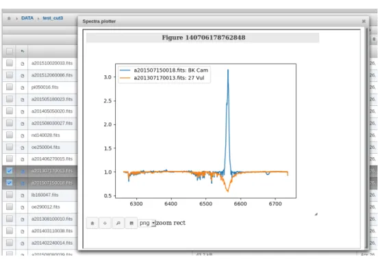
4.1 Example of astronomical spectrum plot of star 31 Pegasi . . . 36
4.2 Example of integratedspectraviewerapplication . . . 43
4.3 JupyterHub solution Docker deployment . . . 50
4.4 Hadoop cluster deployment on Ondˇrejov servers . . . 53
4.5 Apache Avro schema JSON . . . 56
List of Tables
1.1 Often used actions in UWS REST binding . . . 12
Introduction
The research of the night sky of nowadays is not only focused on data ac-quisition using big astronomical telescopes producing regularly big amount of data. The crucial part of the research is to actually unearth significant infor-mation inside those data. VO-CLOUD is a distributed system that has been developed to help astronomers with exactly this part. It allows astronomers to acquire data from big astronomical archives, execute preprocessing and data mining jobs on distributed workers and visualize the final results of the spe-cific data mining method to the user. However, the problem is that currently there is no way to visualise or explore data that are already stored on the VO-CLOUD server. The visualization is critical because the astronomers should be able to review the state of spectra in the every stage of spectra processing. The aim of this thesis is to analyse a present workflow and deployment of the VO-CLOUD server and to design a solution that would allow a user to visualize astronomical spectra inside a web browser application and explore them easily using an integrated Jupyter web application. Further, presented thesis examines ways in which the VO-CLOUD server can be extended to al-low a user to enqueue jobs that use Apache Spark framework for a large-scale data processing and Hadoop Distributed File System (HDFS) as a storage for this kind of jobs. Lastly, the possibility of involvement of the Docker con-tainer platform technology is examined in order to facilitate the deployment of certain parts of the VO-CLOUD system.
Chapter
1
Technology overview
VO-CLOUD is complicated system that adopts many concepts and technolo-gies that reader should understand before reading this Master’s thesis. Also, the task of the work is to integrate additional technologies to already created system. This chapter is dedicated to the explanation of these concepts and technologies that will be used later on in the text.
1.1
Virtual Observatory
The Virtual Observatory (VO) concept is nowadays very popular among as-tronomy community. Whereas in the past astronomers had to wait even a couple months to access the telescope, today they can practically instantly access data they want using the concept of VO. Virtual Observatory addresses challenges such as data management, analysis, distribution and interoperabil-ity [1].
”The VO is a system in which the vast astronomical archives and databases around the world, together with analysis tools and com-putational services, are linked together into an integrated facil-ity.” [1]
The VO concept and additional associated technologies and recommenda-tions have been developed by the International Virtual Observatory Alliance (IVOA). The IVOA is an organisation with a mission to ”facilitate the in-ternational coordination and collaboration necessary for the development and deployment of the tools, systems and organizational structures necessary to enable the international utilization of astronomical archives as an integrated and interoperating virtual observatory.” [2]
The VO-CLOUD system is tightly connected with the concept of Virtual Observatory. It allows user to obtain data from the remote services imple-menting the VO principles using special VO protocols, store the data in the
1. Technology overview
provided storage, preprocess them to an appropriate format and apply a spe-cific data mining method. All of this can be operated easily within a user’s web browser.
1.2
Java EE
The whole current solution of the VO-CLOUD system is built upon Java EE Programming Language Platform (Enterprise Edition). The Java EE platform is an extension of the Java SE platform (Standard Edition) which provides the core functionality for the Java programming language. The Java EE en-riches the Java SE platform with additional concepts and technologies that are mostly used in server multi-tiered environments and makes the development of Java server applications much easier.
”The aim of the Java EE platform is to provide developers with a powerful set of APIs while shortening development time, re-ducing application complexity, and improving application perfor-mance.” [3]
Unlike the Java SE platform where every built application can be executed directly on the Java Virtual Machine (JVM) – the environment where every Java application is running, the Java EE applications are usually deployed into an environment that supports all Java EE technologies that the application intents to utilize. This environment is called Java EE server. The Java EE serves is an application that implements APIs from the Java EE platform and provides the standard Java EE services [3]. There are many implementations of the Java EE server. The reference implementation originally started by Sun Microsystems, nowadays developed by Oracle Corporation is an open-source server called GlassFish1. There are many more implementations of the Java EE server, some of them are open-source other are commercial. The one that is necessary to mention here is an open-source server WildFly2 originally developed by JBoss, now continuously developed by Red Hat. The WildFly is the server where the VO-CLOUD system is currently running on.
The Java EE specification contains many technologies that should simplify development of the server sided applications. Following sections are dedicated to the explanation of Java EE technologies that are related to the VO-CLOUD system.
1.2.1 Java Persistence API
The Java Persistence API (JPA) is a technology that considerably simplifies usability of relational databases inside Java EE applications using a principle
1
https://glassfish.java.net/
2
http://wildfly.org/
1.2. Java EE
@Entity
public c l a s s UserAccount implements S e r i a l i z a b l e {
private s t a t i c f i n a l long s e r i a l V e r s i o n U I D = 1L ; @Id @GeneratedValue ( s t r a t e g y = GenerationType .AUTO)
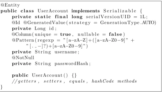
private Long i d ; @Column ( u n i q u e = true, n u l l a b l e = f a l s e) @Pattern ( r e g e x p = ” [ a−zA−Z ] + ( [ a−zA−Z0−9] ” + ” [ . −] ? ) + [ a−zA−Z0−9] ” ) private S t r i n g username ; @NotNull private S t r i n g passwordHash ; public UserAccount ( ) {} // g e t t e r s , s e t t e r s , e q u a l s , hashCode methods }
Figure 1.1: Fragment of simple user account Entity JPA class
called Object-Relational Mapping (ORM).
”The Java Persistence API (JPA) is a Java standards-based solu-tion for persistence. Persistence uses an object relasolu-tional mapping approach to bridge the gap between an object-oriented model and a relational database.” [3]
A programmer implementing an application using relational database does not have to have any knowledge of Standard Query Language (SQL) – a lan-guage that is used for querying and manipulating data inside relational data-bases. The JPA framework does everything for him. A programmer simply implements a Java class (in terms of JPA called Entity class) and annotates it and its attributes with special Java annotations. The framework creates mapping between these objects and tables inside a relational database. Fig-ure 1.1 demonstrates an fragment of a simple Entity class representing a user account. The class will be mapped to the tableuseraccountinside relational database containing exactly 3 columns: id, username, passwordhash. The JPA frameworks provides special class EntityManagerthat provides API for communication with the relational database using above mentioned Entity classes. If a programmer requires more complicated database queries he can also use the Java Persistence Query Language (JPQL) – a simple string-based language similar to SQL used to query entities and their relationships [3].
One great advantage of using the JPA framework is the fact that an ap-plication does not have to know any information about database itself. The application only specifies the name of so-called Persistence Unit. The
Persis-1. Technology overview
tence Unit is configured on the Java EE server and the configuration consists of items such as database connection URL, login credentials, query timeouts, connection drivers and many others. The principle of pulling configuration from application to server ensures portability of the application. In fact, ap-plication on one server can use for example PostgreSQL3 relational database and it can also be redeployed without recompilation to the server utilizing MySQL4 relational database.
1.2.2 Java Servlet Technology
The Java Servlet Technology is very important in the Java EE specification because many other technologies are built upon it.
”A servlet is a Java programming language class used to extend the capabilities of servers that host applications accessed by means of a request-response programming model. Although servlets can respond to any type of request, they are commonly used to extend the applications hosted by web servers. For such applications, Java Servlet technology defines HTTP-specific servlet classes.” [3]
Servlets have very simple lifecycle. The lifecycle is controlled by the web container of the Java EE server where the servlet has been deployed. When a request is mapped to a servlet, the container performs following steps on order to serve a response. [3]
1. If container does not contain an instance of the servlet, the container:
a) loads the servlet class if it has not been done already, b) creates an instance of the servlet class,
c) calls servlet’s methodinit to perform servlet initialization.
2. Calls service method of the servlet instance with two method param-eters representing servlet request object and servlet response object.
Container can also decide that a servlet instance is no longer necessary and remove it from the container. Before it does so it finalizes servlet by calling methoddestroy.
From the implementation point of view the Java Servlet Technology is implemented in packagesjavax.servletandjavax.servlet.http. The first package contains interfaceServlet that every servlet class must implement. The most important methods of this interface are aforementioned methods
init, service and destroy [4]. The first package also contains one of the
3
https://www.postgresql.org/
4
https://www.mysql.com/
1.2. Java EE
@WebServlet ( ” / h e l l o−w o r l d ” )
public c l a s s H e l l o S e r v l e t extends H t t p S e r v l e t {
private s t a t i c f i n a l long s e r i a l V e r s i o n U I D = 1L ;
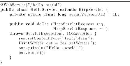
public void doGet ( H t t p S e r v l e t R e q u e s t req , H t t p S e r v l e t R e s p o n s e r e s ) throws S e r v l e t E x c e p t i o n , I O E x c e p t i o n { r e s . s e t C o n t e n t T y p e ( ” t e x t / p l a i n ” ) ; P r i n t W r i t e r o u t = r e s . g e t W r i t e r ( ) ; o u t . p r i n t l n ( ” H e l l o , w o r l d ! ” ) ; o u t . c l o s e ( ) ; } }
Figure 1.2: Servlet code fragment example
class implementing Servlet interface –GenericServlet. This class can be used to implement a generic service – protocol independent servlet.
The most important subclass of GenericServlet is HttpServlet from package javax.servlet.http that provides an abstract implementation of the HTTP protocol [4]. Method service in implementation of this class delegates requests to one of the methoddoXXXwhereXXXis one of the methods of HTTP protocol (GET,HEAD,OPTIONS,POST,PUT,TRACEorDELETE). Figure 1.2 demonstrates an example of a simple ”Hello, World!” servlet application. The application returns string ”Hello, world!” whenever HTTP GET method is called on the servlet’s endpoint (for example when web browser connect to the servlet’s endpoint URL).
It is important to understand what the servlet’s endpoint actually is and how to specify it. As it is possible to see in the example 1.2, the class
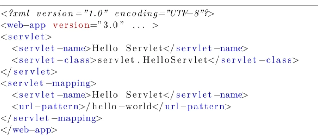
HelloServlet is annotated with WebServlet annotation. The value of this annotation specifies a path relative to the path of deployed Java EE appli-cation. For instance, if the servlet application is deployed on the URL ad-dress http://example.org/app, the servlet endpoint from the example 1.2 ishttp://example.org/app/hello-world. TheWebServletannotation can be also replaced by utilizing a configuration file web.xml, where deployment configurations are specified in XML format. An example of such a configura-tion of HelloServletfrom the example 1.2 can be seen in the figure 1.3.
1.2.3 JavaServer Faces
JavaServer Faces (JSF) is an important technology of the Java EE platform that focuses on simplification of web user interface development. It is built upon Java Servlet technology. In contrast to Java Servlet technology where
1. Technology overview <?xml v e r s i o n =”1.0” e n c o d i n g=”UTF−8”?> <web−app v e r s i o n=” 3 . 0 ” . . . > <s e r v l e t> <s e r v l e t−name>H e l l o S e r v l e t</s e r v l e t−name> <s e r v l e t−c l a s s>s e r v l e t . H e l l o S e r v l e t</s e r v l e t−c l a s s> </s e r v l e t> <s e r v l e t−mapping> <s e r v l e t−name>H e l l o S e r v l e t</s e r v l e t−name> <u r l−p a t t e r n>/ h e l l o−w o r l d</u r l−p a t t e r n> </s e r v l e t−mapping> </web−app>
Figure 1.3: Servlet mapping configuration
servlet class contains implementation of both presentation and behavioral part of user interface, JavaServer Faces framework splits these parts to different units.
”One of the greatest advantages of JavaServer Faces technology is that it offers a clean separation between behaviour and presenta-tion for web applicapresenta-tions.” [3]
The implementation of web user interface of the Java EE application using JavaServer Faces framework consists of two different types of files: XHTML files and so-called Managed Beans. XHTML files represent a presentation part of the user interface – visual side of one page in standardized XML format [3]. There are two different types of XML tags that can be used inside XHTML format. Standard HTML tags and special JSF tags. Whereas HTML tags have no special meaning for the JSF framework and they are mostly passed directly to the client’s web browser, the JSF tags add additional functionality beyond the static HTML pages. They allow to bind data changes, actions and events of the page to Java methods specified in Managed Beans using a special syntax called Expression Language [5]. JSF tags can represent any web view component from a single text field to complicated data table offering sorting and filtering functionality. For example following fragment of XHTML code represents a simple input text field of the HTML input form:
<h:i n p u t T e x t v a l u e=”#{f o o . username}” />
The #{...} syntax is in fact the Expression Language that binds value of this input field to the usernamefield of the Managed Bean named foo. The binding has two functionalities:
• When a page is being rendered for a client the value of the input field is set to the value of usernamefield in fooManaged Bean.
1.2. Java EE
• When the input form is filled and submitted back to a server by client the new value of this input field is stored in the Managed Bean.
The set of JSF tags is easily extendable by using additional XML name-spaces in the root tag of the XHTML document [6]. Using this principle, one can use additional extended components that are not available in pure JSF framework. VO-CLOUD system uses one of such popular JSF extensions – the open source framework named PrimeFaces5.
Managed Bean by definition [3] is a simple Java class that must fulfil following rules:
• It must have non-parametric constructor in order to be able to instan-tiate it anytime without parameters.
• It must have defined name that is available for Expression Language. Managed beans have usually default name inferred from the name of Java class, however it can be renamed using XML descriptor files or Java annotations.
• It must define a scope.
Choosing the right scope for every Managed Bean is an important part of application design. ”Scope defines how application data persists and is shared.”[3] The two most important scopes are request and session scopes. Data inside Managed Beans annotated with request scopes survive only for a single client’s HTTP request, whereas data from session scoped beans are saved to a session storage of the specific client and they survive multiple HTTP requests. The drawback of the session scoped approach is the fact that session storage consumes memory of a server and it complicates scalability of the application because it requires replication of the session storage to additional server instances.
1.2.4 Enterprise JavaBeans
Enterprise JavaBeans (EJB) is a powerful technology that is also part of the Java EE specification. Enterprise bean is a component that runs inside EJB container, a runtime environment in the Java EE server [3]. It is important to note that not every Java EE server has implemented the EJB container and so application written with the EJB functionality cannot be deployed to such servers. For example Apache Tomcat6 server supports many Java EE technologies, however it is only servlet-based server and so there is no support for EJB components. Part of the VO-CLOUD system uses EJB thus it is necessary to deploy them to EJB enabled server such as earlier mentioned GlassFish or WildFly server.
5
https://www.primefaces.org
6
1. Technology overview
The purpose of EJB components is to encapsulate the business logic of an application and to make an development of large, distributed application somewhat easier [3]. The EJB framework pulls responsibilities like security, concurrency and transaction management from a developer to the EJB con-tainer itself. It also provides special API, like asynchronous method invocation and timer service that allows to schedule an operation execution or to execute periodically in specified time intervals.
1.3
Universal Worker Service
The Universal Worker Service (UWS) pattern is an important concept that is involved in the VO-CLOUD system. The UWS recommendation has been developed by IVOA organization and it is extensively used in astroinformatics in cases where synchronous and stateless services are not an option. First, let’s explain what these terms actually mean.
The majority of simple web services are synchronous and stateless. Syn-chronous service is such a service where client waits for the service response after sending a request. Stateless service means that service does not have to remember any state of a communication with client. The state is stored on the client’s side and every client’s request contains all information necessary for processing a response. This is one of basic principles of so-called RESTful services where the REST (Representational State Transfer) is an architec-tural style, developed as an abstract model of the Web architecture to guide our redesign and definition of the Hypertext Transfer Protocol (HTTP) and Uniform Resource Identifiers (URI) [7].
There are two reason why synchronous and stateless services are sometimes not sufficient:
• Processing of response from the passed request can take very long time, sometimes even days.
• Service parameters or results can take large amount of memory space and transferring them through a data channel is not achievable in reasonable time.
It is often necessary to work with big data and long running tasks in astroinfor-matics. UWS pattern has been developed as a way of solving aforementioned problems.
The UWS recommendation specifies how to build asynchronous, stateful and job oriented services [8]. Whereas in synchronous services responses are expected to be almost instantly processed from requests and passed back to a client, clients using asynchronous services of UWS pattern only get identifier of newly created job. Issued jobs are being executed on a server without necessity of client’s interaction or even a connection. After the execution of a
1.3. Universal Worker Service
job is done, results are being linked with the job’s identifier. Clients use job’s identifier to query phase of execution of the job, to download results and to manipulate with the job itself. They can for example abort already running job if its results are no longer relevant.
”A UWS consists logically of a set of objects that may be read and written to in order to control jobs.”[8] These objects are addressable as a distinct web resources and each object has its own URI – it uses the same principle of binding as in RESTful services. Relations between individual UWS objects can be seen in figure 1.4.
• Job – represents a single executable job
• Job List – top-level resource collection; every job must be inside one of these collections
• Phase – represents the execution phase of a job
• RunID – a unique identifier of a job inside a job list collection
• Owner – an identifier representing the job’s owner
• Execution Duration – maximal duration of a job execution in seconds; service provider aborts the job if the duration is exceeded
• Destruction Time – absolute time when the job and its results should be removed from a job list collection
• Quote – a UWS service prediction when the job is likely to complete
• Error – human-readable message specifying the reason why a job failed
• Parameter List – list of parameters passed to a UWS service
• Result List – list of Result objects
• Results – an object representing one of the results of a job execution A UWS pattern uses the same guidelines for mapping operations over resources to the HTTP methods as in a RESTful web services – HTTP GET
method is mapped to operation read, POST to operation create, DELETE to operation delete and PUTto operation update. The set of operations create, read, update and delete are often shortened to an abbreviation CRUD. Table 1.1 shows the most important operations over a UWS service API.
It is also important to mention in more detail a UWS object Phase that specifies the current execution phase of a respective job. ”The job is treated as a state machine with the Execution Phase naming the state.” [8] Phases’ names are self-explanatory and their state machine diagram can be seen in the figure 1.5.
1. Technology overview
class UWS obj ects
JobList Job Quote ExecutionDuration Error ResultList Result Phase ParameterList Parameter DestructionTime Ow ner runID 0..* 1 1 1 0..1 1 0..* 0..1 0..* 1 1 0..1
Figure 1.4: Relations of UWS objects [5]
Table 1.1: Often used actions in UWS REST binding [5]
Method URI Description
GET /{jobList} listing of all Jobs
GET /{jobList}/{id} summary of specified Job GET /{jobList}/{id}/phase phase of the specified Job GET /{jobList}/{id}/results results of the specified Job POST /{jobList} creates new Job
POST /{jobList}?PHASE=RUN creates new Job and puts it into execution queue
POST /{jobList}/{id}/phase ?PHASE=RUN
puts already created Job into execution queue POST /{jobList}/{id}/phase
?PHASE=ABORT
aborts specified Job
DELETE /{jobList}/{id} deletes specified Job
1.3. Universal Worker Service stm Domain Model Initial PENDING QUEUED EXECUTING COMPLETED ERROR ABORTED Final Final Final PHASE=RUN PHASE=ABORT PHASE=ABORT PHASE=ABORT
Chapter
2
Analysis of the current solution
The understanding of the current solution of VO-CLOUD system is crucial for the task of the thesis. This chapter is dedicated to a description of VO-CLOUD system’s responsibilities, explanation of the system’s architecture, description of the system’s workflow and the current state of deployment on the servers. First, let’s describe architecture of the VO-CLOUD system.
2.1
Architecture
VO-CLOUD is a distributed system, which means that it is comprised of hardware or software components located at networked computers that com-municate and coordinate their actions only by passing messages to achieve their task [9]. The system consists of three main components:
• Master server – The main component of the distributed system. Web application that an experimenting user communicates with.
• Universal worker – The computational component. Master server del-egates the computational tasks conducted by an experimenting user to these components. Provides web service for communication with the Master server.
• Specific preprocessing or data mining application – An application that takes passed data and creates an output requested by the user. This application is called as a process from the Universal worker.
It is important to fully understand each of these components and there-fore following sections are dedicated to fully explain their technologies and responsibilities.
2. Analysis of the current solution
2.1.1 Master server
Master server is a web application completely written in the Java EE platform. Responsibilities of the Master server are following:
1. Provide web GUI for communicating with the experimenting user’s web browser application.
2. Provide storage where users can save their data and use them for further experiments and provide web interface to manage the storage.
3. Allow users to upload new files to the Master server’s storage directly from the user’s device.
4. Allow users to download new files to the Master server’s storage from the passed HTTP or FTP resource URL.
5. Allow users to download new files from spectra archives using special astronomical protocols SSAP and DataLink.
6. On the user’s request enqueue new computational job to the Universal worker, await job’s completion, download results back and present them to the user.
7. Allow user to abort currently running job.
Whole web user interface is written using JavaServer Faces (JSF) tech-nology. Master server also requires database for persisting multiple pieces of information, for example user accounts and or executional jobs that have been created by individual users. VO-CLOUD uses Java Persistence API (JPA) framework for utilizing the persistence storage. Moreover, for simpli-fication of transaction and security management VO-CLOUD Master server utilizes Enterprise JavaBeans technology. This means that the Master server has to be deployed on a Java EE server containing EJB container and thus supporting EJB technology.
Users communicate only with the user interface of the Master server. Ev-ery user that wants to work with VO-CLOUD system must be authenticated and thus one of the Master server’s additional responsibilities is to offer a reg-istration form to newcomer users. When user logs in the system, he can do set of operations depending on his authorization level – user role. VO-CLOUD distinguishes between three following user roles:
• USER – User with this role has read-only access to the VO-CLOUD’s storage and can create new jobs from the set of non-restricted job types.
• MANAGER – User with this role has in addition to USER role write permissions to the system’s storage and he can also create jobs of a restricted type.
2.1. Architecture
• ADMIN – User with this role has in addition toMANAGERpermissions to view jobs of all users in the system, to change users’ settings (e.g. set new password or change user role) and to change configuration of available Universal workers.
The storage of VO-CLOUD system is directly mapped to the filesystem where VO-CLOUD has been deployed – it has tree structure of files and folders. There are in total five ways to get data to the system’s storage:
1. A user can directly upload files from his local device through VO-CLOUD’s web user interface.
2. A user can command the server to download file/files from remote lo-cations using FTP or HTTP protocol. By using this method server can download multiple files if passed location points to folder in FTP server or to directory listing of HTTP protocol.
3. A user can command the server to download astronomical spectra from VO databases using protocols SSAP and DataLink. These two proto-cols have been developed as IVOA recommendations. SSAP is basically a protocol that allows to query astronomical spectra fulfilling specified filter conditions and it returns a list of spectra together with meta-data [10]. These spectra could be either directly downloaded, or, if VO service supports it, the DataLink protocol can be used to apply addi-tional spectra transformations on the service provider’s side before a download [11].
4. A user can command the server to store an output of any computational job to the system’s storage.
5. VO-CLOUD’s storage can be also modified by directly modifying a folder structure on the side of server where the Master server has been deployed (e.g. by connecting to the server directly through SSH protocol and modifying data using terminal commands).
Master server’s user interface also offers operations to download selected files from server’s storage to user’s device, to delete selected files, to create new folders, to rename files, etc. Note that operations changing the storage’s state can be issued only by users that have user roleADMIN orMANAGER.
Master server provides functionality for user to create a new computational job. Every job is represented by a job type and a configuration in JSON data format. Job type is in fact the choice of a specific preprocessing or data mining application. Job types are divided to two categories:
• Non-restricted jobs – Jobs that can be created and executed by any logged in users.
2. Analysis of the current solution
• Restricted jobs – Jobs that can be created and executed only by users with higher permissions because to fully utilize their potential it is nec-essary to have write permissions to the system’s storage.
There are currently three types of jobs that can be executed on the VO-CLOUD system. Preprocessing and Random Decision Forest (RDF) method that has been implemented by Andrej Paliˇcka in his Bachelor’s thesis [12] and Self-Orginizing Maps (SOM) method that has been developed by Luk´aˇs Lopatovsk´y in his Bachelor’s thesis [13]. Preprocessing job type takes spectra stored in the system’s storage and it preprocesses them to the format that is an input of RDF and SOM job types. Due to necessity to store data from preprocessing job type back to the VO-CLOUD’s storage the preprocessing job type is set as a restricted job. RDF and SOM job types are non-restricted. In fact, multiple workers supporting a single specific job type can be con-figured. Master server selects from the list one worker that is the least loaded and delegates the computational job on it through UWS worker’s interface. After the execution of a job has started, the Master server periodically checks worker’s job phase through UWS API and when the execution stops, the Mas-ter server downloads results from the worker and it commands worker to delete results on its side. User can view the execution phase of every created job. Jobs’ phases are directly mapped to phases of UWS pattern (see figure 1.5).
2.1.2 Universal worker
Computational jobs are not executed by the Master server itself but they are delegated to computational components of the distributed system – generic workers. Worker has following responsibilities in the VO-CLOUD system:
1. It provides UWS service that the Master server communicates with.
2. It parses JSON configuration for every new job and downloads all nec-essary files from the Master server that are listed in the configuration and are therefore necessary for computation.
3. It passes JSON configuration together with downloaded files to a specific preprocessing or data mining application.
4. It stores computed results until the Master server downloads them.
The worker is a relatively simple web application written in the Java EE platform. As it has been already stated in its responsibilities it must expose a UWS interface that the Master server communicates with. A JavaServlet Techology is involved in the UWS service implementation. No additional Java EE technologies (especially EJB) are used in the worker’s implementation and thus it can be deployed on lightweight Java EE server that has no EJB container (e.g. Tomcat).
2.1. Architecture
In the original implementation of VO-CLOUD system (originally named VO-KOREL [14]) there had to be an implemented application for each indi-vidual type of workers. Every new preprocessing or data mining method re-quired also a new worker application implementation. Moreover, every server where such workers have been deployed can have different settings, i.e., the path to the preprocessing or data mining application could be different. It was necessary to build an individual package for each server and worker type. Source codes of these applications were almost identical with the exception of a few lines of codes and configuration strings. This approach was detrimental for maintenance as every minor change in the source code required multiple recompilations and deployments.
This approach was changed as the result of Jakub Koza’s Bachelor’s thesis that brings a new concept called Universal worker.
”A universal worker is a new type of the servlet based application that is used instead of all other worker application types. The idea is to deploy only one instance of universal worker applica-tion on one computer worker node where multiple computaapplica-tional executable applications are supported.”[5]
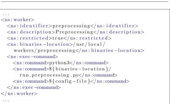
Universal worker is configured using a XML configuration file that matches XSD schema specially created for a Universal worker concept [5]. The schema can be seen in appendix C. Universal worker uses multiple job list collections instead of only one – one job list per one worker XML tag configured in the XML configuration file. The fragment of a such worker’s configuration can be seen in figure 2.1.
As can be seen in the example 2.1 the most important part of worker’s configuration is actually a specification of a process call. Whenever some job should be started on the Universal worker, the worker actually creates a new working directory. All files that are necessary for a job execution are downloaded to this directory. Also the JSON configuration that was passed as a job parameter is saved into this directory as a file. Finally, the process specified in the XML configuration is executed in this directory and a path to the configuration JSON file is passed as a parameter to this process (this is caused by the last command tag in XML configuration containing special substitution sequence ${config-file}.
Workers have been specifically designed to constitute the distributed part of the VO-CLOUD system. There can be multiple workers on multiple ma-chines. If there are more workers for a single job type, VO-CLOUD system automatically chooses the one that is the least loaded. In the matter of de-ployment it is essential that VO-CLOUD’s Master server has network visibil-ity to individual workers in order to communicate with their UWS interface. However, workers do not have to be exposed to users’ devices at all. If it is expected that workers should be able to download data from VO-CLOUD’s Master server the visibility must be bidirectional.
2. Analysis of the current solution . . . <ns:w o rk e r> <ns: i d e n t i f i e r>p r e p r o c e s s i n g</ns:i d e n t i f i e r> <ns:d e s c r i p t i o n>P r e p r o c e s s i n g</ns:d e s c r i p t i o n> <ns:r e s t r i c t e d>t r u e</ns:r e s t r i c t e d> <ns:b i n a r i e s−l o c a t i o n>/ u s r / l o c a l / w o r k e r s / p r e p r o c e s s i n g</ns:b i n a r i e s−l o c a t i o n> <ns:e x e c−command>
<ns:command>python3</ns:command> <ns:command>${b i n a r i e s−l o c a t i o n}/ r u n p r e p r o c e s s i n g . py</ns:command> <ns:command>${c o n f i g−f i l e}</ns:command> </ns:e x e c−command> </ns:w o r k e r> . . .
Figure 2.1: Universal worker configuration fragment
2.1.3 Specific preprocessing or data mining application
VO-CLOUD’s Universal worker component would be useless without an appli-cation that is capable of preprocessing passed data or unearthing new relevant information from them. As it has been already stated there are currently three of these applications – Preprocessing, SOM and RDF. All of them are writ-ten in Python programming language and their behaviour can be altered by changing an input JSON configuration. These applications are simply called as a new process from the Universal worker component. Despite Python being used as a technology for all three job types, there is no limitation on technol-ogy used, i.e., any process that can be executed on worker’s hosted system can be used for purposes of the Universal worker component.
Universal worker redirects standard output stream and standard error stream of application’s process to its own temporal files that are afterwards passed to the Master server together with results. Also the exit status code of the process is passed back to the Master server. If the status code is equal to zero, the process is considered to be successfully ended and the job’s phase is set to COMPLETED state. Otherwise, job’s phase is set to ERROR state. A user can go through standard output and error files on the Master server to uncover a reason for the process failure.
Applications executed by the Universal worker can also create an visual-ization output that the Master server can present to the user. It was designed this way because every job type can require different type of visualization. Vi-sualization is optional and there are two types of viVi-sualization that the Master server can utilize:
2.2. Deployment
• Static visualization – Process produces static image/images that are placed directly to the working directory. These images are directly pre-sented to a user in a web interface. Master server supports following image formats: PNG,JPEG,GIF.
• Dynamic visualization – Process produces a simple web application. In order to do so the process must produce index.html file as a starting point of the web application that must be placed directly in the work-ing directory. Master server renders content of this file inside a special HTML tag IFRAME that basically allows to run another web page in-side a web page. Process can also produce additional HTML files and link those files via standard hypertext relative links. It can also con-tain a JavaScript code for additional scripting capabilities. By using this approach the computational application can for example render a complicated clickable visualization with spectra rendering capabilities.
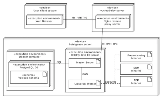
2.2
Deployment
In order to be able to continue with this Master’s thesis it is important to explain the deployment of the current solution as this is the state that is going to be extended. VO-CLOUD system is currently deployed on two servers at Stellar Department of the Astronomical Institute of the Czech Academy of Sciences in Ondˇrejov. These servers are named vocloud-dev
and betelgeuse. Whereas vocloud-dev is only a virtual server with rela-tively small amount of computational resources, betelgeuse is a powerful physical server with 12 CPU cores supporting Hyper-Threading technology (24 virtual CPU cores) and 128 GiB RAM memory. However, unlike the
vocloud-dev server, the betelgeuse server is especially for security reasons not available publicly. Therefore, there is a reverse proxy server Nginx7 de-ployed on the vocloud-dev server. The reverse proxy simply forwards all incoming HTTP/HTTPS requests starting with URI /vocloud-betelgeuse
to the Java EE server hosted on the betelgeuseserver. It also redirect URI
/ to the previous one, therefore the VO-CLOUD system is available on URL address https://vocloud-dev.asu.cas.cz.
Whole VO-CLOUD system is currently deployed on thebetelgeuseserver on the Java EE server called WildFly8. There is a single Master server in-stance and a single Universal worker inin-stance deployed on the WildFly server. The Universal Worker is configured so that it provides a job execution service for Preprocessing, RDF and SOM job types. Master server requires a rela-tional database for its funcrela-tionality. There is a PostgreSQL9 database that is
7 http://nginx.org 8 http://wildfly.org 9 https://www.postgresql.org
2. Analysis of the current solution «device» betelgeuse server RDF binaries SOM binaries Preprocessing binaries Universal Worker Master Server «execution environment»
WildFly Java EE server
«schema» vocloud-schema «execution environment» PostgreSQL DB «execution environment» Docker container «device» vocloud-dev server «execution environment» Nginx reverse proxy server «device»
User client system «execution environment» Web Browser HTTP/HTTPS HTTP/HTTPS SQL executes UWS
Figure 2.2: Deployment diagram
deployed also on thebetelgeuseserver inside a Docker container. Docker10is very powerful technology that considerably simplifies deployment of applica-tion components on different machines. This technology is explained in detail in the following chapter because it is a crucial technology for for the purposes of this work.
Deployment diagram of the current solution can be seen in the figure 2.2.
2.3
Workflow example
For the sake of completeness, let’s describe a scenario of user’s communica-tion with the VO-CLOUD system. A user in this scenario needs to down-load data from a VO archive, to apply preprocessing on them and to apply Self-Organazing Maps (SOM) method to find similarities between passed as-tronomical spectra [13]. As the user intents to use the restricted job type –
Preprocessing – he must have either a MANAGER user role orADMIN user role.
1. User logs into the VO-CLOUD system using his username and password.
2. User navigates through VO-CLOUD’s storage tree structure and select-s/creates a directory where spectra from VO archive should be down-loaded.
10
https://www.docker.com
2.3. Workflow example
3. User clicks Append new files using SSAP button, he fills in all neces-sary input parameters and he configures a DataLink protocol settings (if DataLink protocol is supported by the VO archive and if user wants to use it).
4. User commits the download request. Progress of this request and possi-ble errors can be seen on a dedicated page.
5. When the download is completed, user continues on page of a Prepro-cessing job creation. He either creates a JSON configuration file from scratch or he selects one of the pre-created configurations. Files that should be preprocessed and preprocessing parameters are specified in the JSON configuration.
6. User starts a preprocessing job. Progress can be seen on a dedicated page.
7. After the preprocessing job is completed, user opens details of the job and checks that there is an expected output.
8. User then stores an output of the preprocessing job to system’s storage in order to have it as a source for additional experiments.
9. In a similar way to the preprocessing job, user creates a new SOM job and as an input he selects an output of the preprocessing job stored in the system’s storage.
10. When the SOM execution job is completed, user opens details of the job. SOM job type provides an interactive visualization that user can deeply explore and it can help him to unearth new interesting information.
Chapter
3
Requirements analysis
This chapter is dedicated to the description of all functional and non-functional requirements that are demanded by the new version of the VO-CLOUD sys-tem. The fulfilment of these requirements is the aim of this Master’s thesis. Before diving into these requirements it is important to explain all new tech-nologies that are going to be involved in the new version of the system.
3.1
New technologies
The basis of this work is in fact integration of many new technologies to an existing solution of the VO-CLOUD system in order to simplify scientific work with the system and to extend its capabilities. The comprehension of these technologies is crucial for the practical part of this thesis, thus this section should introduce these technologies to the reader.
3.1.1 Docker
One of the most important technologies that was used in the practical part is Docker. Docker technology has been already mentioned in the section ex-plaining VO-CLOUD’s deployment 2.2 because the database server of the currently deployed solution uses a Docker container. Docker is a software container platform where piece of software is packaged into isolated contain-ers [15]. The containcontain-ers are functionally very similar to the virtual machines, however, containers in Docker platform do not bundle a full operating system, but only software libraries and settings required to make the software work as needed [15].
”Docker containers running on a single machine share that ma-chine’s operating system kernel; they start instantly and use less compute and RAM. Images are constructed from filesystem
lay-3. Requirements analysis
ers and share common files. This minimizes disk usage and image downloads are much faster.”[16]
Docker containers are isolated from each other and they are even isolated from the system hosting the Docker containers. This approach offers great security benefits. Nevertheless, it is possible to link Docker containers together using a Docker linking functionality, if it is necessary. For example, it is a standard approach to deploy a database and an application server on two different Docker containers and link these two containers together.
There are two important terms in Docker terminology that must be ex-plained:
• Docker image – Docker images are basically immutable snapshots of a Docker container. They have layered structure comprised of commits that were applied on the base image. Docker images are created by calling a build Docker command that takes a special Dockerfile file containing instructions that are gradually processed to produce the final Docker image. It is also possible to extend an existing image to create a new image with added functionality. Built Docker images can be pushed to remote repositories and thereafter they can be easily pulled on every device that requires them.
• Docker container – Docker containers are instances of Docker images. Every Docker image can be started using a Docker command run and this is the way to create a new Docker container. Multiple Docker con-tainers can be created from a single Docker image and multiple Docker containers can be running on a single host machine.
For illustration, let’s demonstrate an example of fast PostgreSQL database deployment using a Docker technology by using a single terminal command: d o c k e r run −−name db −d −p 5 4 3 2 : 5 4 3 2
−e POSTGRES USER=<username>
−e POSTGRES PASSWORD=<password>
p o s t g r e s
This is how a database server is currently deployed on thebetelgeuseserver. The command does following actions:
1. It pulls postgresDocker image from the public Docker repository11 if it is not pulled already in the hosted system.
2. It creates a new Docker container nameddb. Database in the container has specifiedusernameand password.
11
https://hub.docker.com
3.1. New technologies
3. It exposes TCP port 5432 from the container to port 5432 on the hosted system.
4. It starts a newly created container in the background and it prints unique container’s identifier.
The most time consuming operation is pulling of Docker image from a repos-itory. If the image is already pulled on the hosted system, the Docker run
command is processed almost instantly.
3.1.2 Apache Hadoop
The Apache Hadoop is a an open-source project developed by the Apache Software Foundation. It is a framework specially developed for the distributed processing of large data sets across clusters of computers using a single pro-gramming model. The Apache Hadoop infrastructure can scale up from the single machine to thousands of servers, each offering its computational and storage resources [17]. The Apache Hadoop consists of following modules[17]:
• Hadoop Common – The common utilities that are necessary for other Hadoop modules.
• Hadoop Distributed File System (HDFS)– Specially designed distributed file system that provides high-throughput access to stored data. This module is explained in more detail in the next section 3.1.3.
• Hadoop YARN – A framework for managing cluster resources and sche-duling computational jobs.
• Hadoop MapReduce – A system of parallel processing of large data sets. Even though MapReduce is very important concept in the Apache Hadoop infrastructure, this technology is not involved in the practical part of this thesis and it has been substituted for the Apache Spark compute engine. The Apache Spark is explained in section 3.1.4.
It is important to note that the whole Apache Hadoop framework is built on the Java technology.
3.1.3 Hadoop Distributed File System
As it has been already stated, Hadoop Distributed File System (HDFS) is one of the core modules of the Apache Hadoop framework infrastructure. It is a distributed filesystem very similar to other distributed file systems, however, HDFS is highly fault-tolerant and it was specifically designed to be deployed on low-cost hardware [18].
HDFS has a master/slave architecture and it consists of two types of com-ponents:
3. Requirements analysis
• Name Node– Master component that manages the file system namespace and regulates access to files by clients [18]. There is only one Name Node component on the HDFS cluster.
• Data Node– The slave component that manages storage attached to the nodes that they run on [18]. There is usually one Data Node component per each device connected to the HDFS cluster.
Data in HDFS are stored inside blocks. The size of blocks depends on the HDFS settings, however, it is usually 64 MB or 128 MB. Data Nodes have no knowledge about files stored inside HDFS [18]. They manage only their file blocks – each block is stored as a separate file in a local filesystem of Data Node’s device.
An image of entire HDFS filesystem is kept by the Name Node inside its memory. Name Node also decides where each file’s data block should be stored (on which Data Node) and also where other replicas of the same data block should be stored. Replication factor (a number stating how many Data Nodes should carry a given data block) can be set on every HDFS file differently. Replication is an essential feature that ensures fault-tolerance functionality and it also improves computational times on some jobs as some data blocks do not have to be moved from one Data Node to another.
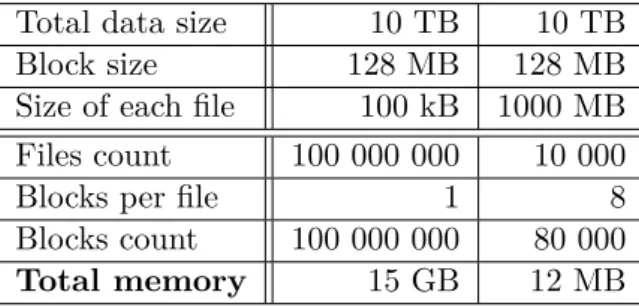
Despite the fact that the HDFS has been designed for big data processing, it is important to point out that it was designed for smaller amount of big files than for many small files. According to Tom White [19], every file, directory and block in HDFS is represented by an object inside Name Node’s memory that takes approximately 150 bytes. For illustration, let’s demonstrate an example of storing in total 10 TB of data. In the first scenario data are distributed in 100 kB files, whereas in the second scenario data are distributed in 1 GB files. Let’s consider that HDFS uses 128 MB sized blocks. As can be seen in table 3.1, the first scenario requires 15 GB of Name Node’s memory, whereas the second scenario only 12 MB. Furthermore, HDFS is primarily designed for streaming access of large files and not of small files, because it causes lots of seeks and lots of hopping from Data Node to Data Node to retrieve each small file [19]. The problem with small files is very urgent in this case as data here usually consist of astronomical spectra – each in a separate approximately 50 kB sized file.
3.1.4 Apache Spark
Apache Spark is an open-source big data general-purpose cluster computing system written in Scala programming language, that provides high-level APIs in Java, Python, Scala and R programming languages and it also provides an optimized engine that supports general execution graphs [20]. Apache Spark software comes also with a rich set of higher-level tools like special Spark’s Ma-chine Learning Library (MLlib), which consists of common learning algorithms
3.1. New technologies
Table 3.1: Comparison of file size behaviour in HDFS Total data size 10 TB 10 TB Block size 128 MB 128 MB Size of each file 100 kB 1000 MB Files count 100 000 000 10 000 Blocks per file 1 8 Blocks count 100 000 000 80 000
Total memory 15 GB 12 MB
and utilities, including classification, regression, clustering, collaborative fil-tering, dimensionality reduction, as well as lower-level optimization primitives and higher-level pipeline APIs [21].
The great advantage of Apache Spark software is that it can utilize an existing Hadoop infrastructure. Spark jobs can be executed in a standalone mode on a single device or in a simple cluster created specially for the purposes of Spark using a tools bundled in the Apache Spark binaries. However, it can also enqueue a Spark job using already mentioned module of Hadoop cluster – Hadoop YARN – that manages cluster resources and schedules computational jobs. The reason why this is usually a better solution for big clusters is that Hadoop YARN is usually precisely configured regarding available resources on each cluster’s node. Moreover, if multiple jobs are enqueued for execution on the Hadoop YARN, the scheduler rather delays an execution of later jobs to offer the executing job full cluster capabilities. Spark framework can also fully utilize the Hadoop Distributed File System (HDFS) as a source of input data sets or as an output job storage.
It is important to explain the main difference between the Hadoop MapRe-duce approach and Spark approach. MapReMapRe-duce has been designed specifically for one-pass computation – it has one Map phase and one Reduce phase. How-ever, many algorithms require multiple-pass computations. If they would be converted to the MapReduce pattern they would require multiple MapReduce jobs to be executed – output of the preceding one would be an input of the successive one. All these intermediate outputs have to be stored in the dis-tributed file system before the next step begins, hence, this approach tends to be slow due to replication and disk storage [22]. Spark on the other hand allows programmers to hold results in memory instead of writing them to disk, especially when they need to work on the same dataset multiple times [22]. If data do not fit into the memory, Spark framework automatically stores part of the data to disk. Since Spark prefers using a fast RAM memory to using a slow disk, jobs executed in Spark framework are usually many times faster than by using a Hadoop MapReduce.
3. Requirements analysis
3.1.5 Jupyter Notebook
The Jupyter Notebook is a web-based application that extends console based approach to interactive computing in a qualitatively new direction [23]. In the past it was common to use some console-based application for an inter-active experimenting over a set of data. However, this approach had many disadvantages that the Jupyter Notebook application is trying to improve.
The Jupyter Notebook application implemented in Python programming language runs as a server on the machine where it was started by using a single command:
j u p y t e r n o t e b o o k
User can connect to it using his favourite web browser application. The di-rectory where this command has been invoked is important because it is set as a working directory for the Jupyter Notebook application. The application consists of three following components:
• Notebook Dashboard – It is basically a file browser that lets user go through the working directory, create, view, modify, delete files, start Notebook documents and inspect already running Notebook documents and Kernels.
• Notebook document– Notebook document is the most important com-ponent of the Jupyter Notebook applications. ”Notebook documents are both human-readable documents containing the analysis description and the results (figures, tables, etc. . . ) as well as executable documents which can be run to perform data analysis.”[24]
• Kernel – The source code from a Notebook document is executed in the component called Kernel. It is basically the computational engine of the Jupyter Notebook application. Multiple Kernels can be configured in the single Jupyter Notebook application, each can support different programming language. For example, one Kernel could execute source code from Notebook documents as a Python code, second as an R code, third as a Scala code, etc. . .
One of the great advantages of the Jupyter Notebook application is the fact that the server can be started on one device and a client can connect to it from another device. All computations take place on the side of the server inside a Kernel component, thus a client can induce computationally challenging experiments on the server side using only a web browser on his potentially slow device and see results either in simple text format or in more sophisticated output, e.g., plots or tables.
3.2. Functional requirements
3.2
Functional requirements
This section lists all new functional requirements that are demanded by the new version of the VO-CLOUD system.
FR 1 Master server must provide an ability to plot selected astronomical spectrum file saved in its storage.
FR 2 Master server must be able to plot multiple spectra files in the same plot.
FR 3 Master server must be able to plot largecsvfiles containing multiple spectra.
FR 4 Master server must provide a zooming and panning functionality in the plotted spectra.
FR 5 Plotted spectra must be able to be exported into ps,eps,pdf,png,
rawand svgimage format.
FR 6 Plotter must be able to loadxaxis values from an externalmeta.xml
file if a spectrum file does not contain it itself.
FR 7 Plotter must be able to plot following spectra file formats: fit,fits,
vot,csv.
FR 8 Master server must provide an ability to switch to Jupyter Notebook environment.
FR 9 Files from the Master server’s storage must be visible and available for experimenting from the integrated Jupyter Notebook environ-ment.
FR 10 Files from completed jobs in the Master server must be visible and available for experimenting from the integrated Jupyter Notebook environment.
FR 11 The Jupyter Notebook must support following Kernel types:
• Python 2
• Python 3
FR 12 Job and storage files from the Master server available to Jupyter Notebook must be read only.
FR 13 The Jupyter Notebook environment must be available only to users authenticated in the VO-CLOUD system.
3. Requirements analysis
FR 14 The Jupyter Notebook environment must be available only to users with a user role eitherMANAGER orADMIN.
FR 15 The Jupyter Notebook environment must provide a writeable direc-tory where users can create their own files and Jupyter Notebooks.
FR 16 Every user’s Jupyter Notebook writable directory must be isolated from all other users.
FR 17 Users should not authenticate again for accessing the Jupyter Note-book environment. Authentication should be straightforward when user is already authenticated in the VO-CLOUD’s Master server.
FR 18 There must be a possibility to create new worker types utilizing the Apache Spark technology – Spark workers.
FR 19 Spark workers must be able to download files from the Master server’s storage directly to the specified path in HDFS.
FR 20 Spark workers must have a defined set of default parameters that are passed to the Spark job.
FR 21 The set of Spark job parameters should be optionally configured by a user in the JSON configuration during the Spark job creation.
FR 22 The output of Spark job should be optionally downloadable from the HDFS back to the VO-CLOUD system.
FR 23 Master server must provide a possibility for user to browse the HDFS. User should be able to modify the HDFS in the same way as the Master server’s storage.
FR 24 Plotter must be able to plot spectra files stored in the HDFS.
FR 25 Files stored inside HDFS must be visible and available for experi-menting from the integrated Jupyter Notebook environment in the same way as the files from the Master server’s storage.
3.3
Non-functional requirements
NFR 1 For security reasons, whole VO-CLOUD system must secure its communication over HTTPS protocol. Incoming connections over HTTP protocols must be redirected to HTTPS connections.
NFR 2 Newly implemented modules should use Docker technology in order to make deployment more straightforward.
3.3. Non-functional requirements
NFR 3 Source codes of the VO-CLOUD system must be published under the Open Source license and they must be publicly available on a public repository.
NFR 4 The new Spark worker type must be able to run on the same ap-plication server as the Master server as well as on an apap-plication server on a different machine.
Chapter
4
Realisation
There are three main goals in the extension of the current solution of the VO-CLOUD system:
• Implementation of spectra plotter
• Integration of Jupyter Notebook environment
• Integration of HDFS and Apache Spark
This chapter is dedicated to the explanation of all of these goals in detail in the following sections.
4.1
Astronomical spectra plotting capability
The current version of the VO-CLOUD system has been originally designed to not differentiate between file types saved in the Master server’s storage. It was user’s responsibility to know what is an actual representation of respective files. Workers of the VO-CLOUD system have been designed in the exactly same way. They basically take a JSON configuration containing the list of files that they should download from the Master server. Then they pass the downloaded files and the same JSON configuration file to some computational process. The process is actually the element that should know what files it is working with. If it is desirable, the process can create a visualization output that Master server can present to the user.
For instance, the Preprocessing job type currently deployed on the VO-CLOUD system processes passed astronomical spectra files and produces an
csvfile containing a preprocessing output. It also produces a si
![Figure 1.4: Relations of UWS objects [5]](https://thumb-us.123doks.com/thumbv2/123dok_us/385607.2542742/28.892.205.687.216.630/figure-relations-of-uws-objects.webp)
![Figure 1.5: State machine of UWS job’s execution phase [5]](https://thumb-us.123doks.com/thumbv2/123dok_us/385607.2542742/29.892.227.657.414.795/figure-state-machine-uws-job-s-execution-phase.webp)