RoboAnalyzer: 3D Model Based Robotic
Learning Software
C. G. Rajeevlochana
1and S. K. Saha
21Research Scholar, Dept. of Mechanical Engineering, IIT Delhi, New Delhi 110 016 [email protected]
2Professor, Dept. of Mechanical Engineering, IIT Delhi, New Delhi 110 016 [email protected]
© K L University 2011
Abstract. Robotics has been a challenging subject for teachers to teach and for students to learn. One of the important aspects that make it difficult is the limited ability to perceive and visualize the concepts appropriately at the time of teaching. Most of the industrial robots are described geo-metrically by their Denavit-Hartenberg (DH) parameters, which are also difficult to perceive for students. Students will find the subject easier to learn if they are able to visualize in 3 dimensions. Tools that aid its learning have been developed by universities across the world as referred elsewhere. This paper proposes RoboAnalyzer, a 3D model based software that can be used to teach robotics subjects to undergraduate and postgraduate courses in engineering colleges in India and elsewhere. In the present implemen-tation, it can be used to learn DH parameters, forward kinematics of serial robots with revolute joints and allows 3D animation and graph plots as output.
Keywords.
1. Introduction
Robotics is a field related to the design, development, control and application of robots in industry, education, research, entertainment, medical applications etc. It has been progressing at a faster rate and hence it finds its place in the curriculum of the universities and is in great demand.
Robotics course for mechanical engineering streams usually includes the theory of the design and working of a robot in the form of drawings, pictures of robots and practical robots in action. Though the first two are easier to achieve by many universities, the last can be achieved by a very few which have access to indus-trial robots. Without seeing a real robot it is very difficult to comprehend its motion in three-dimensional Cartesian space. Hence, there exists a great demand for teaching aids that help students to visualize a robots movement in the form of 3D animations.
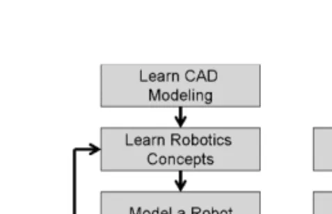
Figure 1. Approaches to learn robotics concepts.
Various robotics visualization tools have been developed over the time that help teachers and students to learn forward kinematics (FKin) and inverse kinematics (IKin) of robots using Denavit Hartenberg (DH) parameters specified by Denavit and Hartenberg (1955) in an effective way. A brief overview of such tools is given in Table 1. There are other advanced software developed by Jaramillo-Botero et al. (2006), Khan et al. (2007) that also cover forward dynamics (FDyn), inverse dynam-ics (IDyn) and trajectory planning. Since many engineering colleges, particularly in India, do not have expensive proprietary software available in their labs, some of the robotics toolkits in MATLAB by Corke (1996), Cakir and Butun (2007) and in LabVIEW by Sanguino et al. (2010) cannot be easily used. Also are available pro-prietary commercial software such as ADAMS (2009), RecurDYN (2009), DADS (2010), SIMPACK (2010) etc. and free software freeCAD (2009) that can perform FKin, FDyn for both open-loop manipulators and closed-loop mechanisms. How-ever, these require first the solid modeling of different bodies of the robot before they are analyzed and animated. The aspect of modeling takes away significant time during a robotics course leaving little time for learning robotics, e.g., FKin or IKin, etc. This is called “Concept to Model” approach as illustrated in Figure 1(a). Alternatively, if a student can skip the modeling part by choosing from default robot examples or generate a robot model by choosing certain parameters and perform its analysis, the student can visualize and learn the concepts in a more effective way. This approach is termed as “Model to Concept” as shown in Figure 1(b). Similar approach is followed in the robotics learning software listed in Table 1. In this paper, the same is followed.
2. RoboAnalyzer
RoboAnalyzer, our proposed robotics learning software is a Microsoft Windows desktop application developed using VisualC# (2009) and OpenGL (2009) using Tao Framework (2009) as wrapper. The following features are considered for its development:
a) It should be easy to use.
b) It should follow “Model to Concept” approach where a model is used to learn the concept, thus helping the students to visualize and learn robotics concepts fast. This way, physics of the robotics will be learnt without going to its mathematics
T able 1. Ov ervie w o f existing FKin and IKin softw are. Allo w Change Graph Softw are Platform in DH FKin IKin Animation Plot Other Details By Y ang et al. (2008) Desktop Applica-tion using OpenGL, C++ No Ye s Ye s (samples) One joint at a time No Import .CAD sample robots. Collision detection. Re v olute (R) joints only By Gonz ´alez P alacios et al. (2009) Desktop Applica-tion using OpenGL, C++ Ye s Ye s Ye s (PUMA) One joint at a time No Inte grated with a 3 R proto-type robot. R joints only By Rohrmeier (2000) W eb application using VRML, Ja v a NA Ye s Ye s (KUKA) KUKA No Def ault KUKA robot model. R joints only R OBO T -DRA W by Robinette and Manseur (2001) W eb application using HTML, VRML and PERL Ye s Ye s Ye s PUMA 560 No DH visualization at link le v el. R and Prismatic (P) joints RModelo by Manseur (2007) Successor of R OBO T -DRA W Ye s Ye s Ye s Ye s NA End-ef fector trajectory . Collision detection. R and P joints By Bruder and W ede w ard (2004) W eb application using MathML, VRML, webMath-ematica, Ja v a Ye s Ye s Ye s No No DH visualization at link le v el. R and P joints
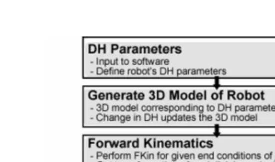
Figure 2. Workflow of RoboAnalyzer.
in detail and making the study of robotics more fun and hence attract more and more students to opt for this subject which is essential for technologically demanding industry applications based on robotic automation.
c) It should have the capabilities of animation and plotting graph of analyses results.
d) It should have least dependencies on other software and should be easily dis-tributable to end users.
e) The program should be modular such that addition of further modules such as IKin, FDyn, IDyn, trajectory planning etc. can be done easily.
2.1 Workflow
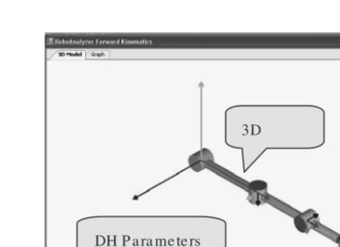
In its present implementation (Figure 2), RoboAnalyzer takes DH parameters of a serial robot (manipulator) with revolute joints as input. It then generates a 3D model (Figure 3) of the robot as per the DH parameters. The 3D viewing window has zoom, pan and tilt capabilities using which 3D model can be viewed from various angles. Simulation parameters can be set and forward kinematics (FKin) analysis can be performed. The results can then be viewed in the form of animation of all the links and the trace of end-effector position, as shown in Figure 4. The plots of the end-effector positions and the joint variables can be drawn (Figure 5) and exported as comma separated value (CSV) files.
2.2 Generation of 3D model
RoboAnalyzer, at present lets a user select 1-R, 2-R, 3-R or 5-R robot. Upon selection it populates default values of DH parameters and a corresponding generic 3D model with cylinders, as shown in Figure 3, for a 3-Rrobot.
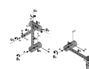
Referring to a 2-Rrobot in Figure 7, the 3D model is generated in OpenGL based on the following approach:
a) Draw cylinder with its base onX1Y1plane with heightb1(alongZ1). Translate the co-ordinate frameX1Y1Z1byb1alongZ1to current frameXcYcZc.
b) RotateXcYcZcbyθ1aboutZc.
c) Draw a cylinder with its base onYcZc with height a1 (alongXc). Translate
Figure 3. 3D Model of a robot.
Figure 4. Robot animation.
d) RotateXcYcZcbyα1aboutXcto reachX2Y2Z2.
e) Start from X2Y2Z2 and repeat steps a −d for the second set of DH para-meters to draw the second link and reachX3Y3Z3, till the end-effector frame is reached.
The DH parameters can be changed and the 3D model updates itself, thus help-ing the student to visualize the robot’s configuration for different set of parameters. Robots with more revolute joints can be modeled similarly. In the present imple-mentation, robots with only revolute joints are modeled and analyzed. Prismatic joints and more realistic shapes of the links will be added in future.
2.3 Robot animation
RoboAnalyzer has a playback deck using which simulation data can be used to animate all the links of the robot in 3D space. This will help the student to visualize
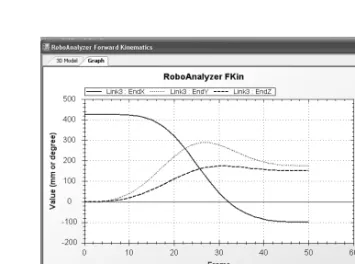
Figure 5. Graph plot of end-effector position.
the robot’s motion. The trace of the end-effector can also be drawn during animation to see the path it follows, as shown in Figure 4.
2.4 Plot graph
An open-sourceC# plot library named ZedGraph (2009) has been integrated with RoboAnalyzer to plot the graph of the end-effector positions during the FKin simu-lation, as shown in Figure 5. The joint rates that are input to the joints can also be plotted. The graph plot can be saved as an image and the data can be exported as a CSV (comma separated values), that can be opened in any spreadsheet application, e.g., in MS-Excel.
2.5 Feedback
The present version of the software is made available through a website, http://www.roboanalyzer.com. The feedbacks from the students of robotics courses are summarized in Figure 6.
3. DH Parameters
Before an example is taken up to illustrate the usage of RoboAnalyzer, its input parameters describing a robot architecture are explained. Note that a robot manipu-lator consists of several links connected by, usually, single degree of freedom (DOF) joints. They can be of revolute (R) or prismatic (P) type. The relationship between the configurations (position and configuration) of a link with respect to its previ-ous link can be represented by four parameters named Denavit-Hartenberg (DH) parameters. Detailed descriptions on the definitions of DH parameters are given in Saha (2008). For a 2-Rserial manipulator configuration shown in Figure 7(a), its DH parameters are given in Table 2(a).
If the above parameters change, e.g., as shown in Table 2(b), the corresponding robot configuration is as shown in Figure 7(b).
Figure 6. Feedback Survey of Roboanalyzer.
4. Forward Kinematics
In this section, a study of forward kinematics of the 2-Rrobot shown in Figure 7(a) will be carried and that will be validated against the forward kinematics relations given in any robotics text book, e.g., Saha (2008). Note that for a robot to perform a specific task, the configuration of its end-effector (EE) in terms of the Cartesian coordinates of the EE and the orientation of the EE should be known in the fixed frame of reference located at the base. A relation between the configuration of the
Figure 7. 2-Rserial manipulator. Table 2. DH parameters of 2-R manipulator (A) Given set.
Joint bi θi ai αi 1 50 mm 90◦ 200 mm 90◦ 2 50 mm 90◦ 150 mm 90◦ (B) Changed set Joint bi θi ai αi 1 50 mm 0◦ 200 mm 90◦ 2 50 mm 0◦ 150 mm 90◦
end-effector and the joint angles (in case of a revolute joint) can be obtained as follows:
Theith set of DH parameters relate the coordinate frameXi+1Yi+1Zi+1attached to theith link with the frameXiYiZi attached to(i−1)stlink. The relationship
can be expressed as the transformation matrix Ti, comprising of both position and
orientation information of the(i+1)stframe with respect to theith frame terms. This is given by Saha (2008).
Ti = ⎡ ⎢ ⎢ ⎢ ⎣ Cθi −SθiCαi SθiSαi aiCθi Sθi CθiCαi −CθiSαi aiSθi 0 Sαi Cαi bi 0 0 0 1 ⎤ ⎥ ⎥ ⎥ ⎦; (1)
WhereC(·)andS(·)stand for cos(·)and sin(·), respectively.
For a serial manipulator with n-joints, the relationship of the coordinate frameXeYeZe attached on the last link (end-effector) withX1Y1Z1on the base
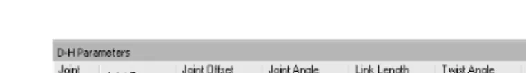
Figure 8. DH parameters input to RoboAnalyzer.
is determined by multiplying all the intermediate transformations as shown below:
Te=T1T2. . .Ti. . .Tn−1Tn (2)
Forward Kinematics (FKin) problem then can be posed as, for known joint positions, find the configuration of the end-effector. It is straightforward for serial systems and yields a unique solution of the configuration.
In the present form of RoboAnalyzer, FKin has been implemented. In order to validate the results for the 2-R robot from RoboAnalyzer, its transformation between the coordinate frameX2Y2Z2andX1Y1Z1given by T1and that between
X3Y3Z3andX2Y2Z2given by T2are derived below:
T1= ⎡ ⎢ ⎢ ⎢ ⎣ C90◦ −S90◦C90◦ S90◦S90◦ 200C90◦ S90◦ C90◦C90◦ −C90◦S90◦ 200S90◦ 0 S90◦ C90◦ 50 0 0 0 1 ⎤ ⎥ ⎥ ⎥ ⎦= ⎡ ⎢ ⎢ ⎢ ⎣ 0 0 1 0 1 0 0 200 0 1 0 50 0 0 0 1 ⎤ ⎥ ⎥ ⎥ ⎦; (3) T2= ⎡ ⎢ ⎢ ⎢ ⎣ C90◦ −S90◦C90◦ S90◦S90◦ 150C90◦ S90◦ C90◦C90◦ −C90◦S90◦ 150S90◦ 0 S90◦ C90◦ 50 0 0 0 1 ⎤ ⎥ ⎥ ⎥ ⎦= ⎡ ⎢ ⎢ ⎢ ⎣ 0 0 1 0 1 0 0 150 0 1 0 50 0 0 0 1 ⎤ ⎥ ⎥ ⎥ ⎦; (4) Moreover, the DH parameters used in equations (3) and (4) are taken from Table 2(a). Now, to find the transformation between the end-effector(X3Y3Z3)and the base(X1Y1Z1), we have to multiply T1and T2which is as follows:
Te =T1T2= ⎡ ⎢ ⎢ ⎢ ⎣ 0 1 0 50 0 0 1 200 1 0 0 200 0 0 0 1 ⎤ ⎥ ⎥ ⎥ ⎦; (5)
The FKin results from RoboAnalyzer are then obtained for the DH parameters as input shown in Figure 8. The output of the results is then saved as a .csv (comma separated value) file which is shown in Figure 9.
Comparing equation (5) and the last 12 elements in .csv file (Figure 9) which represent thex, y, zcomponents of the end-effector and the components of the rota-tion matrix(Q11, Q12, Q13. . . Q33), the results exactly match. Hence the output of RoboAnalyzer is validated.
data, which is used for animation and graph plot. 5. Future Scope
RoboAnalyzer will be further developed to improve the existing features and add new features such as:
a) Prismatic joints b) Inverse kinematics c) Inverse dynamics d) Forward dynamics e) Trajectory planning
f) Analysis of closed-loop and tree–type systems g) Import 3D CAD model into the software.
6. Conclusion
A 3D-model based software to learn robotics concepts is presented in this paper. It is developed using VisualC# and OpenGL that takes the description of a serial robot with revolute joints using DH parameters as input. A student using this software can learn DH parameters and forward kinematics through “Model to Concept” approach, thus bypassing the modeling of robot which is required in the commercial software. FKin analysis can be performed between initial and final values of joint variables and the simulation data can be used to animate all the links of the robots at the same time. Useful graph plots of end-effector posi-tion can also be drawn inside the software and also be exported to a spreadsheet for further processing if needed. The present version is made available through a website (http://www.roboanalyzer.com) and used by about 30 students in robotics courses. Based on the feedbacks of the users, as reported in Section 2.5, improve-ment of the existing features and addition of new modules are underway and will be reported in future.
References
[1] ADAMS http://www.mscsoftware.com/Products/ CAE-Tools/ Adams.aspx (2009). [2] Bruder, S. and Wedeward, K., “An interactive online robotics course,” Automation
Congress, 2004. Proceedings. World, Vol. 15, No., pp. 27–32, June 28 2004–July 1 2004.
[3] Cakir, M. and Butun, E., “An educational tool for 6-DOF industrial robots with quater-nion algebra”, Comput App Eng Educ 15 (2007), pp. 143–154.
[6] Denavit, J. and Hartenberg, R. S., “A kinematic notation for lower-pair mechanisms based on matrices,” ASME Journal of Applied Mechanisms, (1955), pp. 215–221. [7] Gonz´alez-Palacios, M. A., Gonz´alez-Barbosa, E. A. and L. A. Aguilera-Cort´es., “An
interactive software package for the simulation of serial manipulators,” 2009 ECTC Proceedings, ASME Early Career Technical Conference.
[8] Jaramillo-Botero, A., Matta-Gomez, A., Correa-Caicedo, J. F. and Perea-Castro, W., “ROBOMOSP,” Robotics & Automation Magazine, IEEE, Vol. 13, No. 4, pp. 62–73, Dec. 2006.
[9] Khan, W., Zhuang, H. and Angeles, J., 2007, “Robot Visualization System for Windows (RVS4W)”, Centre for Intelligent Machines (CIM), User’s Manual, Department of Mechanical Engineering, McGill University, Montr´eal, Qu´ebec, Canada.
[10] Manseur, R., “Modeling and Visualization of Robotic Arms”, GVE 2007, IASTED International Conference on Graphics and Visualization in Engineering. Clearwater, Florida, Jan 3–5, 2007.
[11] Mateo Sanguino, T. J. and And´ujar M´arquez, J. M., “Simulation tool for teaching and learning 3D kinematics workspaces of serial robotic arms with up to 5-DOF ”, Comput App Eng Educ (Early view 2010).
[12] OpenGL http://www.opengl.org/ (2009). [13] RecurDYN http://www.recurdyn.com (2009).
[14] Robinette, M. F., Manseur, R., “Robot-Draw, an Internet-based visualization tool for robotics education,” Education, IEEE Transactions on, Vol. 44, No. 1, pp. 29–34, Feb 2001.
[15] Rohrmeier, M., “Web based robot simulation using VRML,” Simulation Conference Proceedings, 2000. Winter, Vol. 2, No., pp. 1525–1528, Vol. 2, 2000.
[16] Saha, S. K. (2008), “Introduction to Robotics,” Tata McGraw Hill, New Delhi [17] SIMPACK http://www.simpack.com/ (2010).
[18] Tao Framework http://sourceforge.net/projects/ taoframework/ (2009). [19] VisualC# http://msdn.microsoft.com/en-us/vcsharp/default.aspx (2009).
[20] Yang, X., Zhao, Y., Wu, W. and Wang, H., “Virtual reality based robotics learning system,” Automation and Logistics, 2008. ICAL 2008. IEEE International Conference on, Vol., No., pp. 859–864, 1–3 Sept. 2008.